kuliah02
TRANSCRIPT
8/7/2019 kuliah02
http://slidepdf.com/reader/full/kuliah02 1/22
Sistem Kendali
(Control System )
Modeling in the Frequency Domain
8/7/2019 kuliah02
http://slidepdf.com/reader/full/kuliah02 2/22
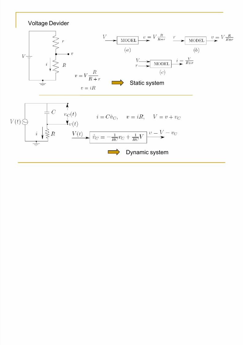
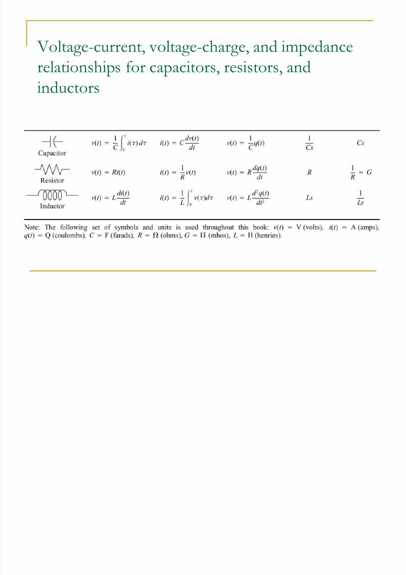
Voltage Devider
Static system
Dynamic system

8/7/2019 kuliah02
http://slidepdf.com/reader/full/kuliah02 3/22
Modeling of Dynamic System
Differential Equation (Dynamic System Model) :
Linear, time-invariant dynamic system (contoh slide sebelumnya)
10 ,, naa . 10 ,, nbb ., : konstanta
1. Frequency Domain Modeling
2. Time Domain Modeling
8/7/2019 kuliah02
http://slidepdf.com/reader/full/kuliah02 4/22
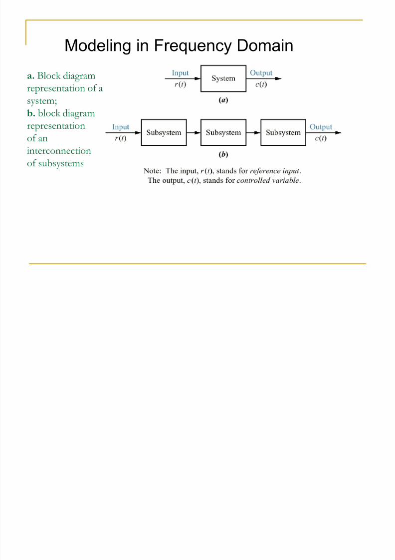
a. Block diagram
representation of a
system;
b. block diagram
representation
of aninterconnection
of subsystems
Modeling in Frequency Domain
8/7/2019 kuliah02
http://slidepdf.com/reader/full/kuliah02 5/22
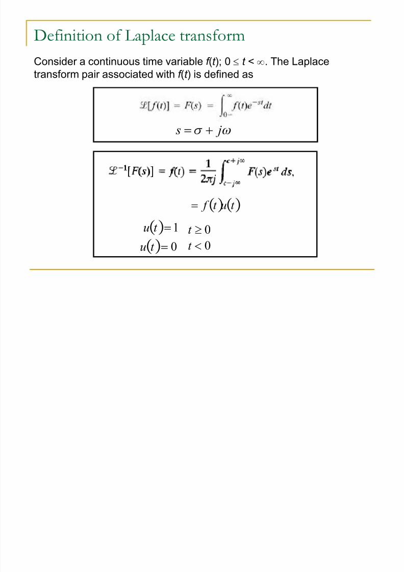
Definition of Laplace transform
Consider a continuous time variable f (t ); 0 e t < g. The Laplace
transform pair associated with f (t ) is defined as
[W js !
t ut f !
1!t u
0!t u
0ut
0t
8/7/2019 kuliah02
http://slidepdf.com/reader/full/kuliah02 6/22
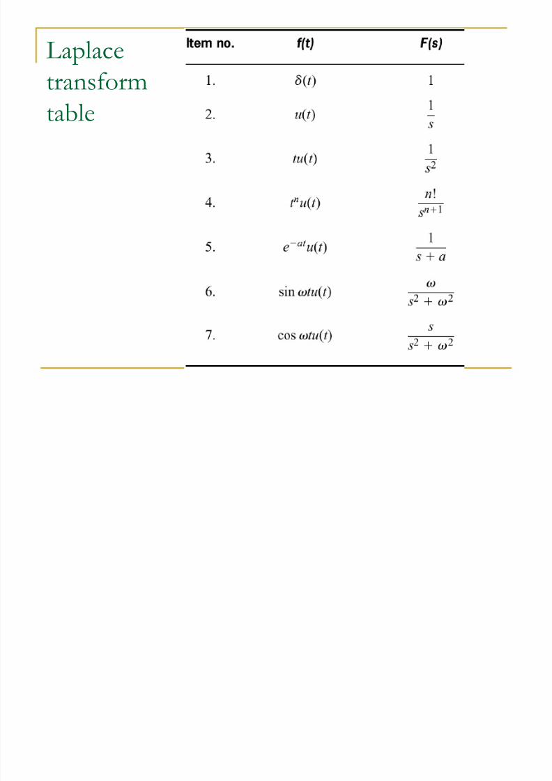
Laplace
transform
table
8/7/2019 kuliah02
http://slidepdf.com/reader/full/kuliah02 7/22
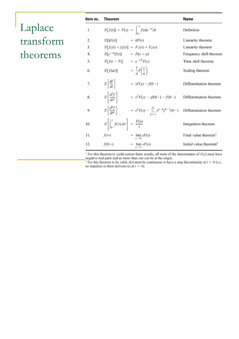
Laplace
transformtheorems
8/7/2019 kuliah02
http://slidepdf.com/reader/full/kuliah02 8/22
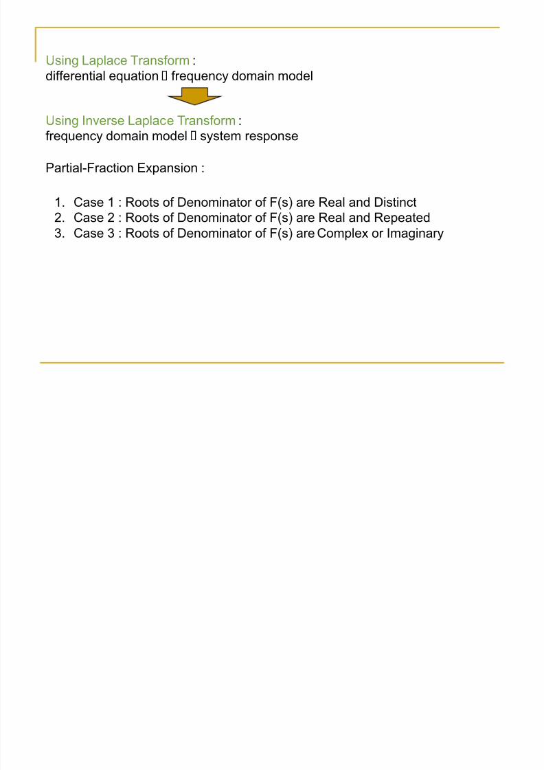
Using Laplace Transform :
differential equation frequency domain model
Using Inverse Laplace Transform :
frequency domain model system response
Partial-Fraction Expansion :
1. Case 1 : Roots of Denominator of F(s) are Real and Distinct
2. Case 2 : Roots of Denominator of F(s) are Real and Repeated
3. Case 3 : Roots of Denominator of F(s) are Complex or Imaginary
8/7/2019 kuliah02
http://slidepdf.com/reader/full/kuliah02 9/22
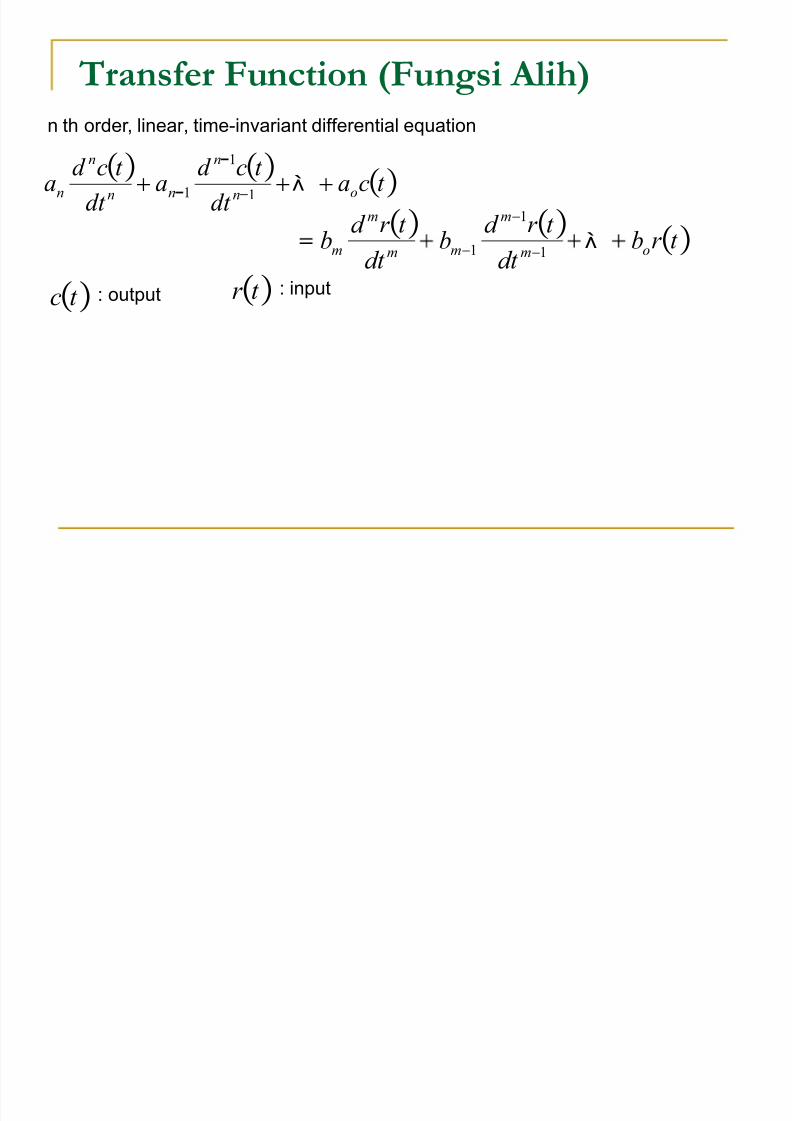
Transfer Function (Fungsi Alih)
t cadt
t cd a
dt
t cd a on
n
nn
n
n .
1
1
1
t r bd t
t r d b
d t
t r d b om
m
mm
m
m
.1
1
1
t c : output t r : input
n th order, linear, time-invariant differential equation

8/7/2019 kuliah02
http://slidepdf.com/reader/full/kuliah02 10/22
Transfer Function
sC asasC sa o
n
n
n
n)1
1 .
Laplace Transform
cond init ial sC asC sasC sa o
n
n
n
n
.1
1
cond init ial sRbsRsbsRsb o ! .1
1
Initial condition = 0
sbsbsb o
m
m
m
m )( 1
1 ! .
o
n
n
n
n
o
m
m
m
m
asasa
bsbsb
s
sC sG
!!
.
.
1
1
1
1Transfer Function
Block diagram of a transfer function
8/7/2019 kuliah02
http://slidepdf.com/reader/full/kuliah02 11/22
8/7/2019 kuliah02
http://slidepdf.com/reader/full/kuliah02 12/22
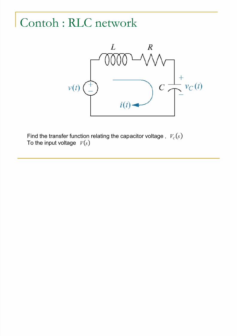
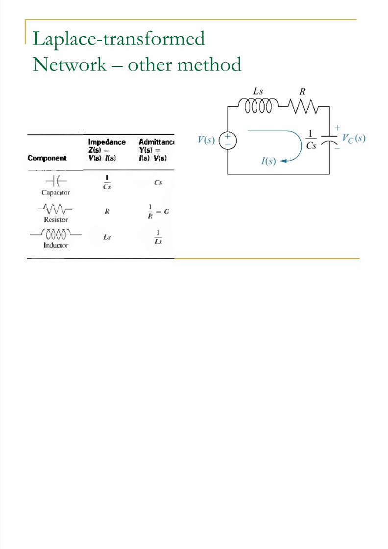
Contoh : RLC network
sV C Find the transfer function relating the capacitor voltage ,
To the input voltage sV
8/7/2019 kuliah02
http://slidepdf.com/reader/full/kuliah02 13/22
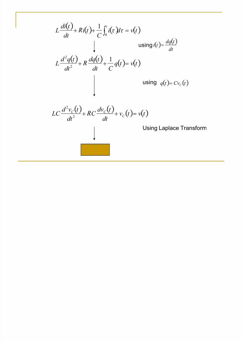
t vd iC
t id t
t diL
t
! ´ X X 0
1
t vt qC d t
t d q
d t
t qd L !
12
2
dt t dqt i !using
t Cvt q C !using
t vt vd t
t d vC
d t
t vd LC C
C C !2
2
Using Laplace Transform
8/7/2019 kuliah02
http://slidepdf.com/reader/full/kuliah02 14/22
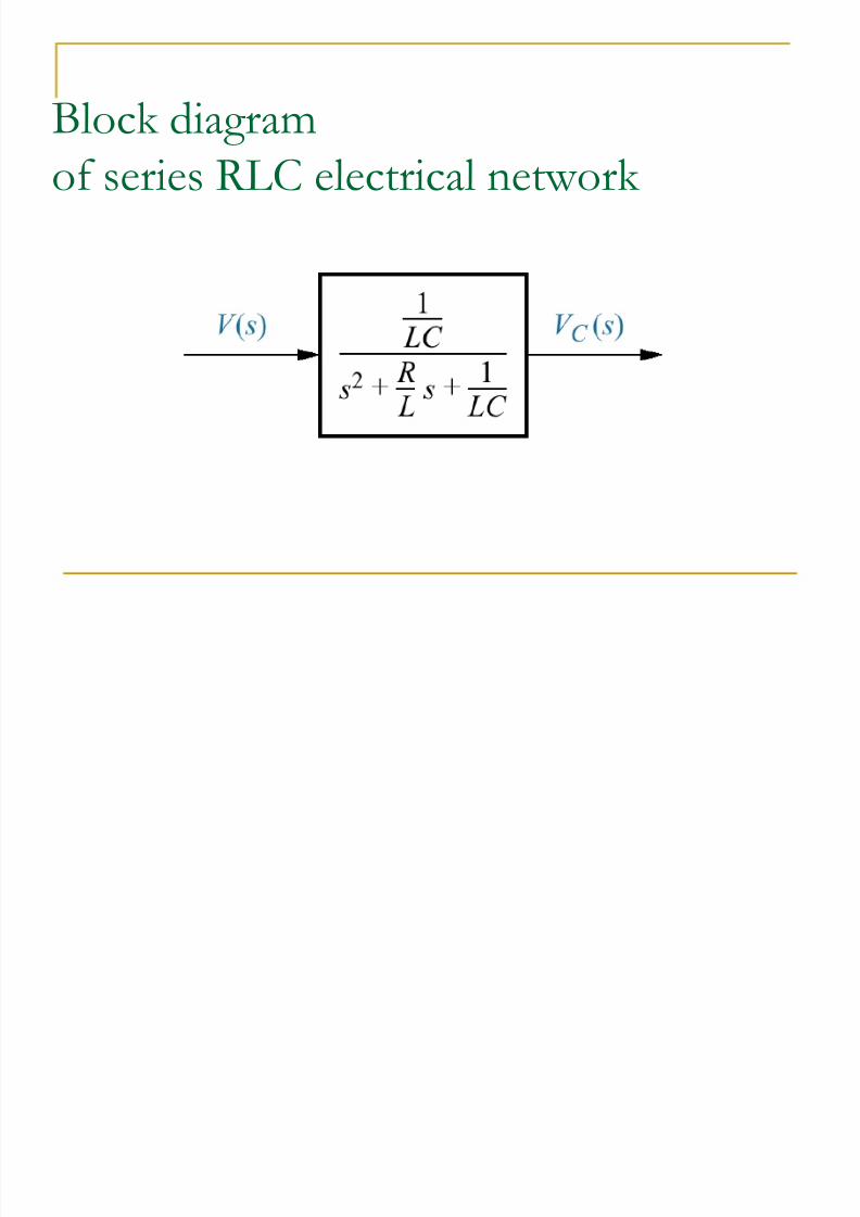
Block diagram
of series RLC electrical network
8/7/2019 kuliah02
http://slidepdf.com/reader/full/kuliah02 15/22
8/7/2019 kuliah02
http://slidepdf.com/reader/full/kuliah02 16/22
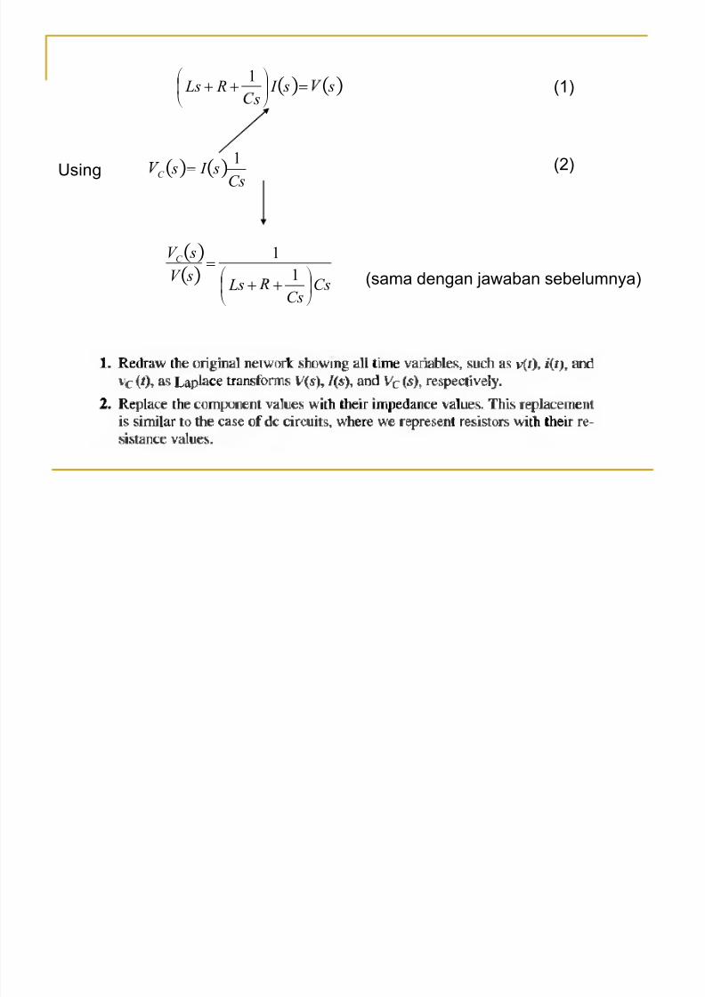
ssI s
RLs !¹º
¸©ª
¨ 1
C s
sI sC
1!Using
CsCs
LssV
sV C
¹º
¸©ª
¨
!1
1
(sama dengan jawaban sebelumnya)
(1)
(2)
8/7/2019 kuliah02
http://slidepdf.com/reader/full/kuliah02 17/22
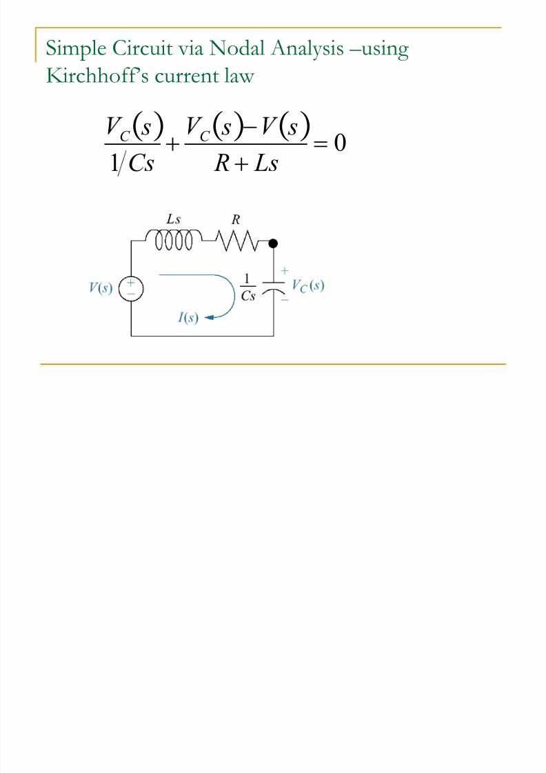
Simple Circuit via Nodal Analysis ²using
Kirchhoff·s current law
0
1!
LsR
ss
C s
sC C

8/7/2019 kuliah02
http://slidepdf.com/reader/full/kuliah02 18/22
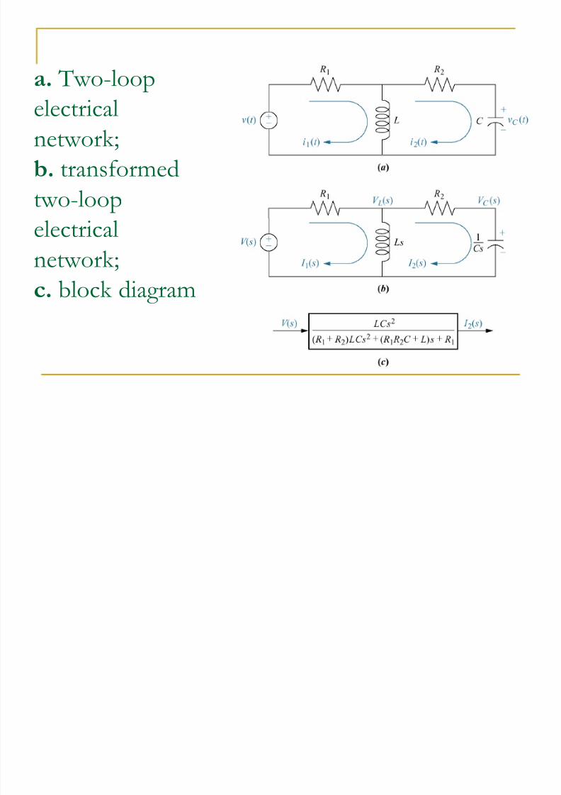
a. Two-loop
electrical
network;
b. transformed
two-loopelectrical
network;
c. block diagram

8/7/2019 kuliah02
http://slidepdf.com/reader/full/kuliah02 19/22
Complex Circuit via Mesh Analysis
1. Replace passive element values with their impedances
2. Replace all sources and time variables withtheir laplace transform
3. Assume a transform current and a currentdirection in each mesh
4. Write Kirchhoff¶s voltage law around each
mesh5. Solve the simultaneous equations for output
6. Form the transfer function
8/7/2019 kuliah02
http://slidepdf.com/reader/full/kuliah02 20/22
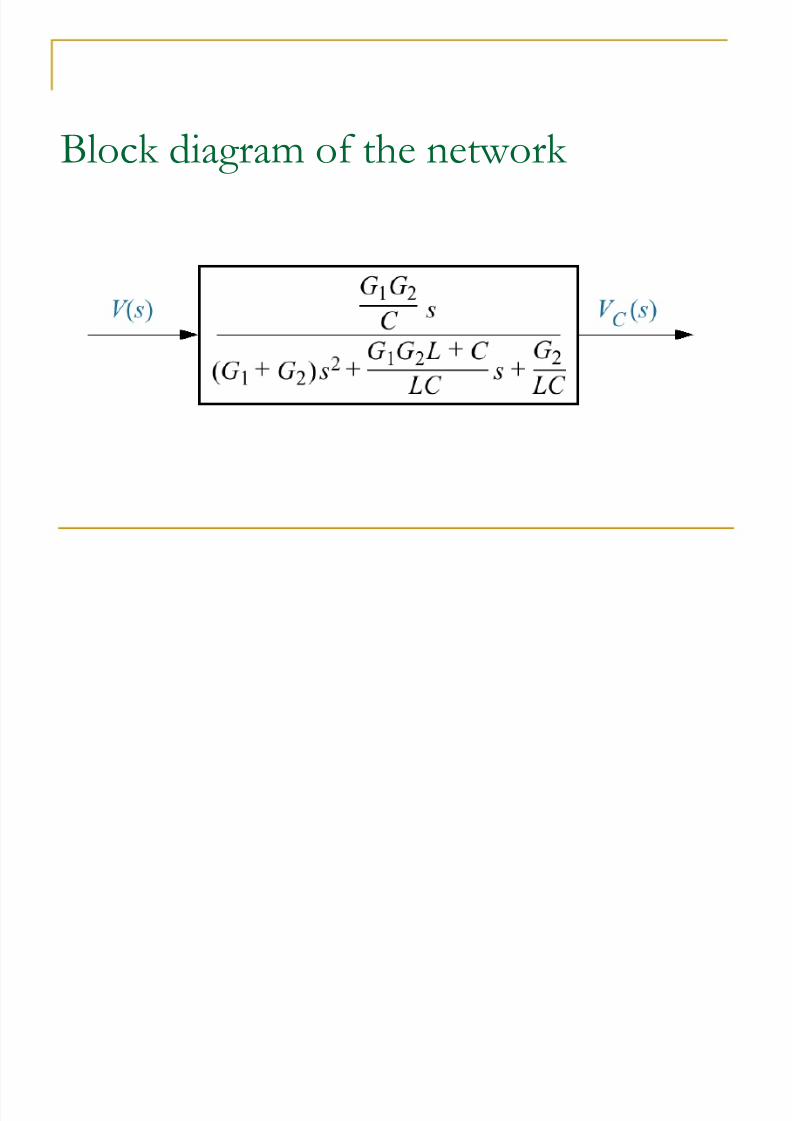
Block diagram of the network
8/7/2019 kuliah02
http://slidepdf.com/reader/full/kuliah02 21/22
a. Two-loop
electrical
network;
b. transformed
two-loopelectrical
network;
c. block diagram

8/7/2019 kuliah02
http://slidepdf.com/reader/full/kuliah02 22/22