completion eng pag425-450ing3
TRANSCRIPT
8/13/2019 Completion Eng Pag425-450ing3
http://slidepdf.com/reader/full/completion-eng-pag425-450ing3 1/26
3.7.1 Introduction
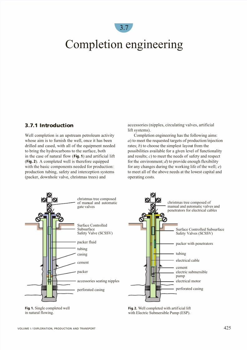
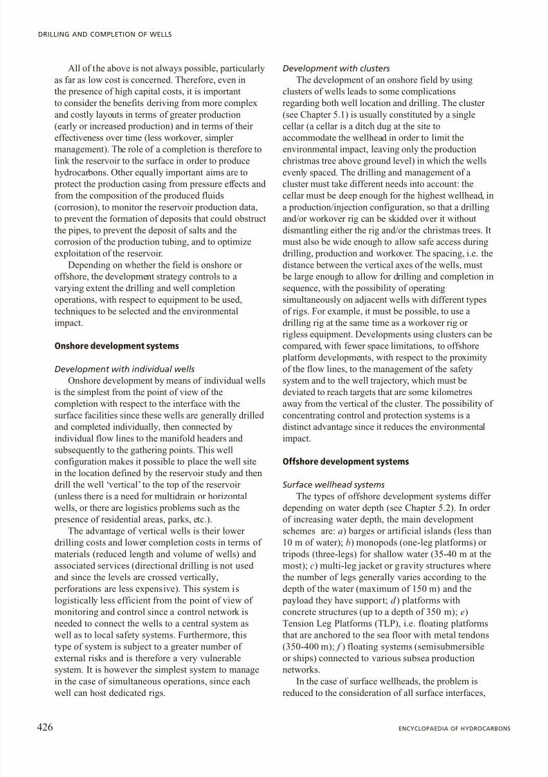
Well completion is an upstream petroleum activitywhose aim is to furnish the well, once it has beendrilled and cased, with all of the equipment needed to bring the hydrocarbons to the surface, bothin the case of natural flow ( Fig. 1) and artificial lift(Fig. 2). A completed well is therefore equipped with the basic components needed for production:
production tubing, safety and interception systems(packer, downhole valve, christmas trees) and
accessories (nipples, circulating valves, artificiallift systems).
Completion engineering has the following aims:a) to meet the requested targets of production/injectionrates; b) to choose the simplest layout from the
possibilities available for a given level of functionalityand results; c) to meet the needs of safety and respectfor the environment; d ) to provide enough flexibilityfor any changes during the working life of the well; e)to meet all of the above needs at the lowest capital and operating costs.
3.7
Completion engineering
425VOLUME I / EXPLORATION, PRODUCTION AND TRANSPORT
christmas tree composed of manual and automaticgate valves
Surface Controlled SubsurfaceSafety Valve (SCSSV)
packer fluid
tubingcasing
cement
packer
accessories seating nipples
perforated casing
Fig. 1. Single completed wellin natural flowing.
christmas tree composed of manual and automatic valves and
penetrators for electrical cables
Surface Controlled SubsurfaceSafety Valves (SCSSV)
packer with penetrators
tubing
electrical cable
cementelectric submersible
pumpelectrical motor
perforated casing
Fig. 2. Well completed with artif icial liftwith Electric Submersible Pump (ESP).
8/13/2019 Completion Eng Pag425-450ing3
http://slidepdf.com/reader/full/completion-eng-pag425-450ing3 2/26

8/13/2019 Completion Eng Pag425-450ing3
http://slidepdf.com/reader/full/completion-eng-pag425-450ing3 3/26
together with problems due to the limitations of spaceand safety related to the execution of simultaneousoperations in restricted space. The aspects to consider are: a) the selection of rigs and their use; b) the wellstructural interface with surface facilities (spacing of the wellheads and wells at each platform leveldepending on the well system size); c) the installationof the conductor pipes (environmental protection tubesconnecting subsea wellhead with the platformwellhead) and their centralisation within the platformstructure (jacket); d ) the tieback system design, i.e. theconnection of the production casings of wells duringthe pre-drilling phase, from the sea floor (see Section3.7.2), and the drilling wellhead; e) the well movementin relation to the f ixed structures (design of wellhead installing system; f ) determination of wellhead vertical movements with respect to the conductor pipedue to temperature variations during production and the relevant movements of flow lines with respect tothe platform structure); g ) the integration of controland safety systems.
Subsea wellhead systemsIn this case, in addition to normal well problems,
there are other needs related to the design and installation of the subsea production system,including: a) the selection of the rigs (either moored or dynamic position rigs); b) the completion running; c)the level perforating phase (opening communication of
production levels with the wellbore); d ) the production phase for clean-up; e) the wellhead installation phase; f ) the flow line installation phase; g ) control umbilicalinstallation phase for subsea wellhead control during
production; h) the transfer of the control system to aremote station; i) the well workover phases during its
productive life performed by means of a rig similar tothat used for initial installation or by means of dedicated rigs.
Completion designStudies for completion design are divided into:
pre-feasibility, feasibility and detailed studies. Normally, pre-feasibility and feasibility studies areaimed at supplying management with accurateeconomic data to approve the start of the development
project. The detailed study is aimed at preparingspecifications for the purchase of materials and theservices needed for the development plan.
Data needed for the development projectThis is a summary of the data needed to prepare
the document defining the basic prerequisites and goals of f ield development in which the wells are an
integral part ( statement of requirement ). These datainclude: a) the PVT (Pressure, Volume, Temperature)
characteristics of the fluids to be produced, i.e. thedensity, viscosity (variable according to pressure and temperature) and related phase diagrams; b) reservoir data regarding the number of productive levels; c) the
production sequence planned; d ) the volumes of hydrocarbons in-place for each level; e) the type of drive mechanism (water drive, solution-gas or gas-capdrive); f ) the forecast of the well flow rates and thecontribution of each level in the case of commingled
production; g ) the forecast of the evolution of the flowrate and of the fractions of the fluid produced; h) the
pressure behaviour forecast (SBHP, Static BottomHolePressure) with respect to the original reservoir
pressure; and i) the minimum flowing pressure (i.e.abandonment pressure) for each well. In addition, inorder to more accurately define the drilling profile, thefollowing must be determined: a) the positioning of the wells on the reservoir top; b) the geological datadefining the petrophysical characteristics as well astheir spatial distribution; c) the mechanical strength of the rocks penetrated; d ) the reservoir structure map; e)the contacts between the fluids; f ) the depth of
production levels and relative pressure gradients; g )drilling data from exploration/appraisal drilling, thatallow the determination of the pressure and temperature gradients; h) any discontinuities; i)overpressures and potential problems.
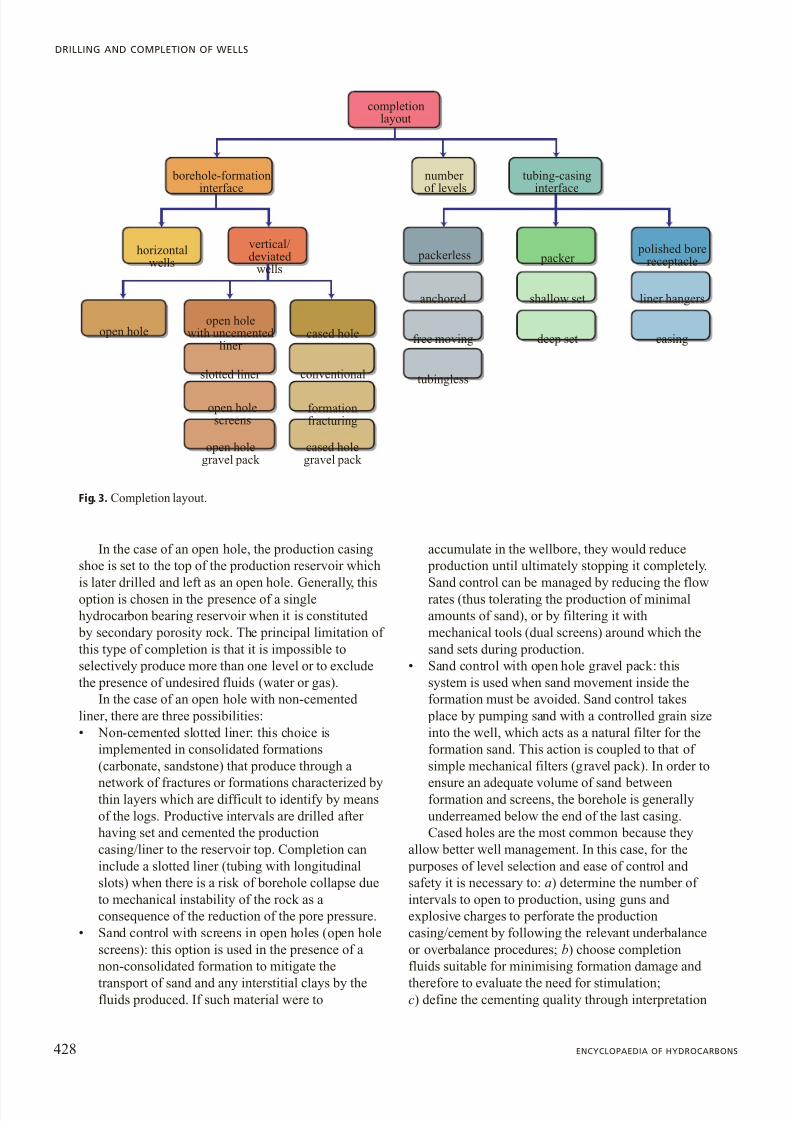
3.7.2 Completion layoutThe completion design follows the flow diagram of Fig. 3, which first identifies the logic sequence for the
borehole-formation interface, then that related to theinterface between the production tubing and casingand, finally, the number of levels to be put into
production, the production sequence and/or the possibility of commingled production from two or more levels.
Borehole-formation interface
The borehole-formation interface differs accordingto whether the wells are vertical, deviated (up to anangle of 60°-70°), sub-horizontal or horizontal (anglegreater than 70°). Traditionally wells have a telescopiccasing profile and involve the use of a greater number of casing sizes the deeper the well while maintaining afixed production casing size. Horizontal wellsgenerally have a borehole that navigates inside thereservoir itself.
Vertical wellsThe interface options for vertical wells can be
divided into three main categories: open hole, openhole with non-cemented liners, and cased hole.
427VOLUME I / EXPLORATION, PRODUCTION AND TRANSPORT
COMPLETION ENGINEERING
8/13/2019 Completion Eng Pag425-450ing3
http://slidepdf.com/reader/full/completion-eng-pag425-450ing3 4/26
In the case of an open hole, the production casingshoe is set to the top of the production reservoir which
is later drilled and left as an open hole. Generally, thisoption is chosen in the presence of a singlehydrocarbon bearing reservoir when it is constituted
by secondary porosity rock. The principal limitation of this type of completion is that it is impossible toselectively produce more than one level or to excludethe presence of undesired fluids (water or gas).
In the case of an open hole with non-cemented liner, there are three possibilities:• Non-cemented slotted liner: this choice is
implemented in consolidated formations(carbonate, sandstone) that produce through a
network of fractures or formations characterized bythin layers which are difficult to identify by meansof the logs. Productive intervals are drilled after having set and cemented the productioncasing/liner to the reservoir top. Completion caninclude a slotted liner (tubing with longitudinalslots) when there is a risk of borehole collapse dueto mechanical instability of the rock as aconsequence of the reduction of the pore pressure.
• Sand control with screens in open holes (open holescreens): this option is used in the presence of anon-consolidated formation to mitigate the
transport of sand and any interstitial clays by thefluids produced. If such material were to
accumulate in the wellbore, they would reduce production until ultimately stopping it completely.
Sand control can be managed by reducing the flowrates (thus tolerating the production of minimalamounts of sand), or by filtering it withmechanical tools (dual screens) around which thesand sets during production.
• Sand control with open hole gravel pack: thissystem is used when sand movement inside theformation must be avoided. Sand control takes
place by pumping sand with a controlled grain sizeinto the well, which acts as a natural filter for theformation sand. This action is coupled to that of simple mechanical filters (gravel pack). In order to
ensure an adequate volume of sand betweenformation and screens, the borehole is generallyunderreamed below the end of the last casing.Cased holes are the most common because they
allow better well management. In this case, for the purposes of level selection and ease of control and safety it is necessary to: a) determine the number of intervals to open to production, using guns and explosive charges to perforate the productioncasing/cement by following the relevant underbalanceor overbalance procedures; b) choose completionfluids suitable for minimising formation damage and
therefore to evaluate the need for stimulation;c) define the cementing quality through interpretation
428 ENCYCLOPAEDIA OF HYDROCARBONS
DRILLING AND COMPLETION OF WELLS
open holegravel pack
completionlayout
borehole-formationinterface
tubing-casinginterface
polished borereceptacle packer packerless
liner hangersshallow setanchored
casingdeep setfree moving
tubingless
cased holegravel pack
open holescreens
formationfracturing
conventionalslotted liner
horizontalwells
cased holeopen hole
with uncemented liner
open hole
vertical/deviated
wells
numberof levels
Fig. 3. Completion layout.

8/13/2019 Completion Eng Pag425-450ing3
http://slidepdf.com/reader/full/completion-eng-pag425-450ing3 5/26
of the logs of specific wells (cementation log);d ) ensure true isolation of the levels. Cased holecompletions can be subdivided as follows:• Conventional: this completion scheme is used
when the formations are stable. The casing perforation is carried out using suitable explosivecharges, which are high-penetration in the event of heavy formation damage induced by drilling fluids,and possibly, with the use of underbalancetechniques to remove the effects of damage.
• With formation fracturing: in this case, given thevery low permeability of the formation,
productivity is improved by creation of induced fractures. To do so a high pressure acid solution isinjected into the formation and a small part of thelevel is perforated in order to concentrate the effectof the pressure. High penetration explosive chargesare necessary and excellent cementing is required so as to limit the fracture.
• Sand control by means of cased hole gravel pack:this scheme is used for sand production control incased holes. Explosive charges are used that can
perforate holes of a certain size (ID, InternalDiameter 0.7'') in the casing in order to facilitatethe passage of controlled grain size sand pumped into the formation. The technique of sand pumpingis very effective in the presence of fractures(frac-pack).
Horizontal wellsCompletion schemes in horizontal wells are similar to those of vertical wells but, in this case, there arefactors that complicate their management. Normally,horizontal wells have very long sections inside the
production level (since the well trajectory isintentionally navigated inside the hydrocarbon bearingzone) and are difficult to manage during the injectionand production phases in terms of pressure losses. It isalso extremely difficult to carry out good cement
bonding even in consolidated formations. The borehole ’s mechanical stability is therefore more
sensitive to geostatic loads in the case of an importantdrop in the static pressure of the reservoir during the
production life. The most common completion schemesare therefore comparable to those used in open holevertical wells. Still, the length of the horizontalsegment and the effect of gravity complicateinstallation procedures of the equipment (there is, for example, a great deal of friction in the lower part of the
borehole, and difficulty in transferring any rotation tothe bottom) and the pumping of the sized sand for sand control. To this end, specific sand control techniqueshave been developed for horizontal wells as well as in
situ expandable mechanical screens to avoid the need for fluid pumping with the transport of solids.
Multilevel productionWith vertical wells that cross reservoirs consisting
of more than one production level with different petrophysical characteristics or containing differenttypes of fluids, the number of levels to be completed must be decided. In horizontal wells, there are similar configurations when step-well trajectories are used inmultilayer reservoirs. Multilayer horizontal reservoir completion configuration is rare and is carried out bysubdividing a horizontal well into step sections,managed more or less individually with valvescontrolled from the surface, both during production(to guarantee optimum drainage of the reservoir) and injection (to ensure stimulation and/or injectivity inthe case of water injection wells).
The types of multilevel completion are listed below.
Completion for commingled production . In thiscase, a number of productive levels are put into
production at the same time, thus mixing the output.The completions are very simple and used when all of the levels have the same pressure regime, similar
production indexes and contain similar hydrocarbons.Otherwise, the most permeable levels would tend to
produce more efficiently than the others which mayresult in cross flow from one level to an adjacent one(when the well is closed and the pressure at the bottomtends to be balanced).
Completion for sequential production . Sequential
level production is implemented either by interventionon the well by opening the sliding sleeves, or throughrecompletion, i.e. first opening to production on onelevel (generally the deepest), pulling out the
production string and then recompleting the well in anupper level.
Single completions with segregated production . Inthis case, a single production tubing is used but levelsare kept separate by packers. When it is envisaged thatthe lower levels will be invaded by water before theothers and their exclusion is incorporated in thedesign, plans can be made for initial simultaneous
production and later segregated production by meansof sliding sleeves or plugs set in the tubing ( Fig. 4 A),or a sequential production from bottom to top; or alternating production producing each level separatelyin sequence ( Fig. 4 B). Sometimes, more productivelevels are opened for production first in order to createconditions compatible with the other levels (i.e. todeplete them), after which simultaneous productioncan be implemented.
Multiple completions with segregated production .As in the above case, the levels are separated by
packers, however, two or more production tubings are
used for simultaneous but segregated production of anumber of levels. Parallel tubing ( Fig. 4 C) or
429VOLUME I / EXPLORATION, PRODUCTION AND TRANSPORT
COMPLETION ENGINEERING
8/13/2019 Completion Eng Pag425-450ing3
http://slidepdf.com/reader/full/completion-eng-pag425-450ing3 6/26
concentric tubing ( Fig. 4 D) may be used. Thesecompletion schemes are generally chosen when it isnot desirable or possible mix the flows of the single
production strings.The schemes shown in Fig. 4 A and 4 B allow both
simultaneous (commingled) production and segregated production for each individual level but not at thesame time. They also make it possible to segregatelevels that might produce water or gas in undesired volumes. These types of completions can also be used ‘creatively ’, for example by installing flow regulatorsor exploiting gas levels to lift oil levels. The schemesshown in Fig. 4 C and 4 D are used primarily in
offshore reservoirs where single string productionwould not be economical since it would require a largenumber of wells.
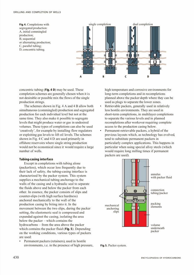
Tubing-casing interfaceExcept in completions with tubing alone
(packerless), which occur less frequently due totheir lack of safety, the tubing-casing interface ischaracterized by the packer system. This systemsupplies a mechanical tubing anchorage to thewalls of the casing and a hydraulic seal to separatethe fluids above and below the packer from each
other. In essence, the packer consists of slips and counter-slips (with high surface hardness)anchored mechanically to the wall of the
production casing by biting into it. In themovement between the two slips, during the packer setting, the elastomeric seal is compressed and expanded against the casing, isolating the area
below the packer – which contains thehydrocarbons – from the area above the packer which contains the packer fluid ( Fig. 5). Dependingon the working conditions, various types of packersare used:
• Permanent packers (retainers), used in hostileenvironments, i.e. in the presence of high pressure,
high temperature and corrosive environments for long-term completions and in recompletions
planned above the packer depth where they can beused as plugs to separate the lower zones.
• Retrievable packers, generally used in relativelyless hostile environments. They are used inshort-term completions, in multilayer completionsto separate the various levels and in planned recompletions after workover requiring completeaccess to the production casing below.
• Permanent-retrievable packers, a hybrid of the previous layouts which, as technology has evolved,tend to substitute permanent packers in
particularly complex applications. This happens in particular when using special alloy steels (whichwould require long milling times if permanent
packers are used).
430 ENCYCLOPAEDIA OF HYDROCARBONS
DRILLING AND COMPLETION OF WELLS
single completion dual completionFig. 4. Completions withsegregated production:A, initial commingled
production;B, sequentialor alternating production;C, parallel tubing;D, concentric tubing.
DA B C
annuluswith packer fluid
connectiontubing/packer
packingelements
volumeunderneath
packer
mechanicalanchoring
slips
Fig. 5. Packer system.

8/13/2019 Completion Eng Pag425-450ing3
http://slidepdf.com/reader/full/completion-eng-pag425-450ing3 7/26

8/13/2019 Completion Eng Pag425-450ing3
http://slidepdf.com/reader/full/completion-eng-pag425-450ing3 8/26
Offshore tie-back systems with platform wellheads.Pre-drilling phase
The exploratory wells drilled with jack-up rigs,where the BOPs are onboard the rig and connected tothe well by means of a marine riser, have casings thatterminate on a special drilling wellhead placed on thesea floor. After the drilling and testing phase, the well
is suspended and completely shutoff on the sea floor.Should the well be recovered, the necessary casings (atleast the production casing and the conductor pipe to
protect against sea and weather) must be reconnected to the surface, and the structure (jacket) wellhead,
complete with christmas tree, is placed on the production structure (monopod or platform). This process is known as tie-back . In reservoir development with platforms, this system is generallyadopted when the wells are predrilled, and performed with semisub or jack-up rigs, before the jacket and
platform are available, even though the platform will be equipped with a drilling rig. This process is lesscostly since it makes it possible to drill thedevelopment wells in parallel to the construction of the
production structures (jackets and top-sided). Thisallows production to start in advance in comparison toa sequential development which first requires platformconstruction and then drilling and completion of thewells. During predrilling the rig is positioned on thevertical of the axis of the slots in the templateanchored to the sea floor, which is a protectionstructure of a series of wellheads, similar to anonshore cluster. The wells are drilled in sequence and the same casings are installed in all of the wells(phases) so as to reduce logistic problems and optimize drilling times. Drilling of each well issuspended when the last casing is cemented to thereservoir top. To do so, the BOP stack is moved fromone well slot to another on the template. The wells arethus temporarily abandoned on the sea floor.Once the jacket and topsides are installed, each wellis tied-back to the surface by the conductor pipe(for environmental protection of the well), and by the
casing (to support the wellhead installed on the platform). The drilling phase of the productioninterval, the completion and the production start-upare carried out using the drilling rig constructed for the platform.
432 ENCYCLOPAEDIA OF HYDROCARBONS
DRILLING AND COMPLETION OF WELLS
swab gate valve
wing gate valve
wing gate valve
control line port
master gate valvewith actuator
master gate valve
top adapter
Fig. 7. Integral christmas tree.
cover plug
tubing hanger
tubing spool
annulus linewith control valves
production linewith control valvescontrol pod
housing
base frame
Fig. 8. Wellheadand subsea christmastree, system with guidelines (courtesyof Cooper CameronCorporation, CameronDivision).

8/13/2019 Completion Eng Pag425-450ing3
http://slidepdf.com/reader/full/completion-eng-pag425-450ing3 9/26
Criteria for wellhead designWellhead characteristics are defined on the basis of
the pressure rating, the Product Specification Level(PSL), i.e. the type of steel used and the TemperatureClass (TC), according the 6A standards of the API and ISO 10423:2003 (ISO, 2003).
Pressure rating . Working Pressure (WP) is def ined as the highest pressure to which a single component,the wellhead in this case, may be subjected during itsworking life. API has conventionally divided wellhead operating pressure ratings into six classes: a) 1 st classto work up to 2,000 psi (13.8 MPa); b) 2 nd class up to3,000 psi (20.7 MPa); c) 3 rd class up to 5,000 psi(34.5 MPa); d ) 4 th class up to 10,000 psi (69.0 MPa);e) 5 th class up to 15,000 psi (103.5 MPa); f ) 6 th classup to 20,000 psi (138.0 MPa).
An increase in the rating is reflected in a rise in thecosts, this is why an accurate determination of therating is of the utmost importance. Given the lack of measurements of the maximum wellhead pressure, theStatic Bottom Hole Pressure (SBHP) is used as theworking pressure, i.e. it is assumed that WP SBHP.This approach is obviously cautionary and leads tosystem oversizing, critical when approaching thetechnological limits of construction (today around 20,000 psi, 138 MPa), and with a heavy impact oncosts. It is therefore advisable to measure the wellhead
pressure during exploratory well tests and to useWP STHP max SF, where STHP max is the maximum
Static Tubing Head Pressure measured and SF is aSafety Factor - chosen on the basis of the uncertaintyof the measurement, defined by the company (for example, SF 1.1 for natural gas wells and SF 1.3 for oil wells). This criterion takes into consideration thestatic tubing head pressure, measured during a testafter the well has been shut-in for a certain period of time, which is the equivalent of the static bottomhole
pressure minus the hydrostatic pressure generated bythe fluid column contained in the tubing (P hyd ), i.e.STHP SBHP – Phyd . If the fluid in the tubing is a drygas, and therefore not subject to further phase changes
during the measuring period (normally 48 hours), it is possible to assume a safety coefficient value (1.1)lower than that assumed in the case of oil (1.3). Oil,which liberates gas in the well and thus develops into atwo-phase state, tends to segregate in the tubing whenthe well is closed (with the heavy components on the
bottom and the lighter components on top). Since thedynamics of this phenomenon might not be completeat the moment of measurement, the static pressuremeasured during a shut-in may be lower than theactual shut-in pressure. For this reason, it is preferableto assume a higher SF to determine the rating and to
assume an average estimated density of the two-phasefluid in the tubing.
Product Specification Level (PSL) . This consistsof a range of values (from 1 to 4) which defines all of the quality controls to which the materials must besubjected during design, construction and testing. Thehighest value is that applied for the most severeinstallation conditions. The PSL of the equipment is
based on a logical process that evaluates the predicted working pressure and the hydrogen sulphide (H 2S)content, since this compound is highly corrosive for steels and lethal to humans. If H 2S is present, the PSLalso accounts for environmental conditions in terms of the vicinity of civilian structures and the applicabilityof the NACE (National Association of CorrosionEngineering) standard specifications for the selectionof materials (MR 01-75 standard; NACE, 2001).The aim of this environmental evaluation is to providethe constructor with design and construction criteria(the PSL) suitable for the different installations,according to the actual working conditions, on the
basis of risk evaluation.Temperature class . This defines the application
limits within a class to which corresponds the choiceof steel grades. A wellhead must commonly meet anumber of temperature classes simultaneously and therefore the relevant materials must be chosen withgreat care (for example, in sub-arctic conditions withtemperature variations between 40°C and 40°C).
3.7.3 Fluids present in the wellCompletion fluid
The completion fluid is present in the well duringcompletion installation or removal. A good completionfluid must be dense enough to ensure a hydrostatic
pressure greater than that of the formation (at least300 psi), contain a minimum amount of solids and, if itdoes contain solids, generate a filtrate that will notdamage hydrocarbon bearing levels. Furthermore, itmust also be viscous enough to ensure the solidstransport capacity. Oil-based drilling muds are rarely
used. Brine, heavy brine or foams are more common.For more details, see Chapter 3.5.
Annulus filling fluid (packer fluid)The packer fluid is the static fluid present in the
annulus between the tubing and the production casingthroughout completion life. It can be the same as thecompletion fluid or any appropriate fluid that ensuresthat its density is maintained over time to balance thestatic reservoir pressure at the bottom of the hole (killfluids). In other words, it must be able to kill the wellin the case of loss, breakage or release of the barrier
created by the packer and tubing. In high pressure and high temperature wells, where the tubing and casing
433VOLUME I / EXPLORATION, PRODUCTION AND TRANSPORT
COMPLETION ENGINEERING
8/13/2019 Completion Eng Pag425-450ing3
http://slidepdf.com/reader/full/completion-eng-pag425-450ing3 10/26
sizing criteria are near the acceptability limits of thesafety factors, it may be advisable not to use a killweight fluid. In fact, in such wells, the highhydrostatic load a fluid with the density characteristicsdefined above (i.e. with a pressure gradient greater than 1.8-2 bar/10 m), together with the accumulation
of high pressure at the head of the production annuluscaused by a possible leak in the tubing, could lead tocasing failure or tubing collapse. The consequences of such an event would be more critical than those to beavoided by means of the counterpressure due to the
packer fluid. The latter however is never to beconsidered a safety barrier.
3.7.4 Impact of safetyon the completion scheme
Whatever the type of completion to be designed, thereare minimum prerequisites that must be respected toensure the safety of the installation with respect to thesurrounding environment and the safety of the
personnel working directly on the well site duringinstallation, production and workover as well as to
protect the people and objects in the vicinity. There areactive and passive safety measures during the various
phases. Active safety measures are those actually or potentially manageable during operation (dynamic barrier). Passive safety measures are those intended toensure that fluids are contained whatever the external
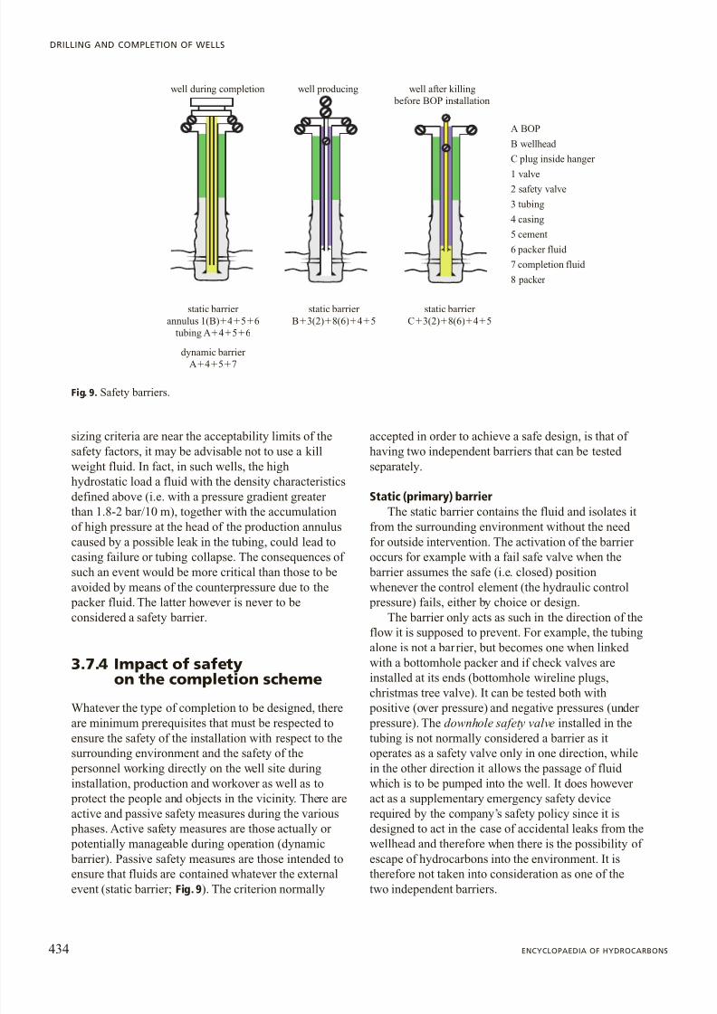
event (static barrier; Fig. 9). The criterion normally
accepted in order to achieve a safe design, is that of having two independent barriers that can be tested separately.
Static (primary) barrierThe static barrier contains the fluid and isolates it
from the surrounding environment without the need for outside intervention. The activation of the barrier occurs for example with a fail safe valve when the
barrier assumes the safe (i.e. closed) positionwhenever the control element (the hydraulic control
pressure) fails, either by choice or design.The barrier only acts as such in the direction of the
flow it is supposed to prevent. For example, the tubingalone is not a barrier, but becomes one when linked with a bottomhole packer and if check valves areinstalled at its ends (bottomhole wireline plugs,christmas tree valve). It can be tested both with
positive (over pressure) and negative pressures (under pressure). The downhole safety valve installed in thetubing is not normally considered a barrier as itoperates as a safety valve only in one direction, whilein the other direction it allows the passage of fluid which is to be pumped into the well. It does however act as a supplementary emergency safety devicerequired by the company ’s safety policy since it isdesigned to act in the case of accidental leaks from thewellhead and therefore when there is the possibility of escape of hydrocarbons into the environment. It istherefore not taken into consideration as one of the
two independent barriers.
434 ENCYCLOPAEDIA OF HYDROCARBONS
DRILLING AND COMPLETION OF WELLS
well during completion well producing well after killing before BOP installation
static barrier annulus 1(B) 4 5 6
tubing A 4 5 6
dynamic barrier A 4 5 7
static barrier B 3(2) 8(6) 4 5
static barrier C 3(2) 8(6) 4 5
A BOP
B wellhead
C plug inside hanger
1 valve2 safety valve
3 tubing
4 casing
5 cement
6 packer fluid
7 completion fluid
8 packer
Fig. 9. Safety barriers.

8/13/2019 Completion Eng Pag425-450ing3
http://slidepdf.com/reader/full/completion-eng-pag425-450ing3 11/26
Dynamic (secondary) barrierThe dynamic barrier contains the fluid and
isolates it from the surrounding environment in acontrolled environment. It is not a classic barrier since the open/closed concept cannot be applied to itand testing its effectiveness is difficult. For example,the denser completion fluid is a ‘dynamic ’ barrier
since it stops the reservoir fluid from flowing thanksto the differential pressure generated by the differentdensities of the fluids. In an interval open to
production, it only guarantees this containmentwhen the two fluids are in static equilibrium. In theopposite case, i.e. when the formation absorbs thecompletion fluid, the weight balance becomesunstable and, if not controlled by reintegratingabsorbed fluids, the well may start to flow. This is
because the level in the tubing is lowered followingabsorption. If not compensated, it in turn causes adrop of hydrostatic pressure on the formation, thus
allowing hydrocarbons to enter the well. Thecompletion fluid can be considered a dynamic
barrier since, for short periods and under closecontrol and observation, its effects can be exploited during tubing substitution operations, in the
presence of the static barrier supplied by the BOP.On the other hand, the packer fluid remains staticduring the well ’s production life from the time whenit is installed until the first workover. Nonetheless, itcannot be considered a barrier because, even if itsdensity is high enough to control the well, itsrheological characteristics may deteriorate with time
and its density thus be altered.
Selection of safety systemsThe above considerations related to barrier
definitions aside, a well ’s safety configuration dependson the policy of the country where the well is operated and of the company operating it. Generalization istherefore absolutely impossible. For example, Table 1and 2 show the minimum criteria that the designer
should respect independently of the geographic area of
435VOLUME I / EXPLORATION, PRODUCTION AND TRANSPORT
COMPLETION ENGINEERING
Table 1. Selection of safety valves: applications
Type of valve Application
Tubing retrievable flapper valve Wells in offshore platforms
Subsea wellsWells with presence of H 2S or CO 2Wells with surface flowing temperature greater than 130 °C
Wireline Retrievable Surface controlled flapper Valve As on insert valve for tubing retrievable SCSSVs(WRSV)
Storm chokes As a backup to the WRSV when there is a control linefailure. Set in the lower wireline nipple
Annular safety system Gas lift wellsESP wells with gas dischargeJet pump wells (under the pumps)
Wireline retrievable injection valves All injection wells (water, waste water, cuttings)
Table 2. Selection criteria for safety valves
Type of well Criteria
Oil production All new offshore developmentsAll onshore naturally
flowing wellsAll wells to be recompleted All isolated wells
Gas production All new offshore developments
All wells to be recompleted Gas storage All wells
Gas injection All wells
Water injection All wells
Artificial lift All gas lift wells in, tubingannulus
ESP wells with tubing,including annulus in the caseof gas discharge
H2S in produced fluids All wells

8/13/2019 Completion Eng Pag425-450ing3
http://slidepdf.com/reader/full/completion-eng-pag425-450ing3 12/26
the world where operations take place. Theseminimum criteria require the use of downhole safetyvalves to form an emergency barrier in the case of uncontrolled production from the well. Such valvesmust be of the fail safe type, they must be controlled from the surface and are normally installed in the
production tubing. They must also have the same pressure rating as that defined for the tubing and thechristmas tree.
3.7.5 Selection of materials
Once the fluid corrosivity characteristics are known,the types of steel must be selected. This activity has to
be started very early because, if it is thought to benecessary to perform control tests on the existingmaterials and qualification tests for new materials,long times are required. Material selection isfundamental for the life of the well because, asidefrom hydrocarbons, H 2S and/or CO 2, chlorides (Cl – ),oxygen (O 2), aerobic or anaerobic bacteria flora mayalso be present. Therefore, the tubing, liner and christmas tree, as well as production casing and thewellhead must be resistant to corrosion. A carefulchoice of steels must take into account the predicted duration of completion, whether there will beworkover during its production life and relative capitaland operating costs.
Methods to control well corrosionMethods for controlling corrosion include one or
more of the following options, depending on their impact on the project cost and development strategies:a) use of tubulars with extra thickness (corrosionallowance) and carefully planned substitutions; b)choice of appropriate corrosion resistant alloys; c)reduction of tensions; d ) elimination of sharp bends;e) elimination of impulsive loads and/or vibrations; f )chemical inhibition through use of a scavengers for O 2and/or H 2S, control of the pH and use of inhibitors; g )
application of an internal coating; h) use of carbonsteel with non-metallic inserts.
The strategy of using corrosion allowance isapplied where there is generalized corrosion in thecarbon steels, and thicker tubing is chosen. In thatcase, substitution of the tubing at set times is
planned, for example when workover on the well dueto reservoir problems is already planned. Options c, d and e are aimed at eliminating stress in situations of Sulphide Stress Cracking (SSC). They are related tothe well profile and are not always attainable. Theycan however lead to the adoption of mixed sections or
sections of tubing in Corrosion Resistant Alloys(CRA) in the zones under greatest stress, limiting
carbon steel to the zones under less stress. The use of these methods requires an adequate evaluation of thestates of stress throughout the length of the tubing.Chemical inhibition with sequestering agents istypical of processes limited in time, for exampleduring drilling, or is applied to fluids in a staticconditions – the packer fluids for instance – in order to avoid damage over time due to action of oxygenand bacterial flora. On the other hand, corrosioninhibitors are used for production/injection fluids.These are generally amine-based substances (seeChapter 5.4) that limit or slow corrosion, coating thetubing wall with a thin f ilm and are generallycomplementary to the use of corrosion allowance.Inhibitors are normally added in small quantities(ppm) to the produced fluids, and in differentconcentrations in all injected fluids. There arevarious methods for using inhibitors in the
production well: injected into the well in cushions(batch treatment), injected into the formation(squeeze treatment), left at bottomhole so that theycan transported by the fluid produced over time, or
by continuous injection. In the last case, their transport to the bottomhole requires the installationof small diameter chemical injection lines banded tothe production tubing. The injection of inhibitorsmust be combined with a detection system on thesurface to evaluate their effectiveness during thewell ’s production life, for example, by means of tests
to evaluate the weight loss. The cost of inhibitors and their management must be carefully evaluated duringdesign because on a long-term basis they may becomparable with apparently more expensive systemssuch as the use of corrosion resistant alloys. Theinternal coating method consists of covering theinternal walls of the production tubing with an in situcured epoxy bicomponent resin. To this end, there areresins that are resistant to aggressive well chemicalsas well as to high temperatures (130 °C) which offer adequate protection to corrosion as long as there isnot excessive wear due to wireline and coiled tubing
trips (see below) in the wells. In fact, such tripsdamage the surface of the walls by friction, thusuncovering metallic areas that are then subjected to a
preferential corrosive attack. The resins used aresensitive to permeation of gas and, in the case of extremely violent decompression, can blister, swelland lose adhesion. For this reason, their applicationmust be carefully analysed. They involve a costroughly 20% higher with respect to carbon steel and the bonus is a reduction of the flow frictioncoefficient. Furthermore, they require specialconnections (CB rings, Corrosion Barrier rings) to
isolate metal to metal seals and avoid damage duringmake-up. The tubing with non-metallic liners is
436 ENCYCLOPAEDIA OF HYDROCARBONS
DRILLING AND COMPLETION OF WELLS
8/13/2019 Completion Eng Pag425-450ing3
http://slidepdf.com/reader/full/completion-eng-pag425-450ing3 13/26
manufactured with tubular material in carbon steel,with internal liners of composite materials (f ibreglass). They have the same function as the internalcoating described above, however they reduce theinternal diameter by at least 5 mm instead of a fewtenths of a millimetre in the case of coatings. Variouscompositions and types of f illing between the tubingand liner (cement, resins) have been identified, and have various applications both in water injectionwells and natural gas wells. For aramidic resins thatare resistant to high temperatures, the cost iscomparable to that of martensitic steel.
Tubular materialsThe tubular materials for wells is collectively
indicated as OCTG (Oil Country Tubular Goods) and classified according to API standards based on: theOutside Diameter (OD) of the tubing (OD 1.05''-4.5'')and of the casing (OD >4.5''); the range of the lengthof each element e.g. for the tubing in terms of range 1(20-24 ft), range 2 (24-32 ft), and range 3 (32-48 ft)and for the casing in terms of range 1 (16-25 ft), range2 (25-34 ft) and range 3 (34-48 ft); the linear weight(lbs/ft or kg/m) for which, once the outer diameters areset, both the thickness and the inner diameters of thetubing (the diameter used for fluidodynamiccalculations) can be determined. Another parameter to
be considered is the drift, a conventional measurementthat defines the maximum diameter of any piece of
equipment that can run inside the pipes (tubing or casing) without it getting stuck. OD-connection is theouter diameter of the collar or of the upset of thethreaded pipe end, i.e. the maximum tubing diameter.Finally, the grade indicates the steel ’s characteristics.
Premium or gas tight connections are used at mostfor production tubing. It is recommended that theseconnections also be used for the casing and productionliners, particularly when the annulus is used for gaslifts or when the packer fluid gradient is lower thanthat of the reservoir (underbalanced). Connections canalso be of the collared or integral type. The substantial
difference between upset or integral connections and collar connections lies in the fact that the latter requirecutting of an extra thread on each tubing and thereforeintroduce an additional potential point of leakage. For this reason, upset connections are preferred inexploration wells. The fact remains that the use of upset connections is limited in time, if they are used repeatedly and then tested, because the number of recuts is limited due to exhaustion of the upset part.Tubing made from corrosion resistant alloy cannot beupset. They are cold worked and upsetting would impair their resistance and require after forging at
temperature and heat treatment that would render the pipe inhomogeneous at its extremities.
Seal elementsThese normally consist of elastomers
(components with high elastic properties) for the gasseal and non-elastomers for anti-extrusion.Elastomers that are used as seal units can bedistinguished into the following configurationsaccording to the function which they must fulfil.O-rings are designed to bear pressure under staticconditions and can also support variations in pressurefor a limited number of cycles; in any case, they tend to be extruded out of their grooves, and thereforethey need rigid support. They are generally used either statically as internal seals for completionequipment or in components that are subject to asingle cycle (pressure equalization systems). TheT-seals/moulded seals are designed as dynamic sealsand are harder than the O-rings. They work withhigher interference and can incorporate anti-extrusion metallic reinforcing elements during hotmoulding. In the form of T-seals, they are often used in tubing hanger seals, while in the form of moulded seals, they are used as dynamic seal packs inside SealBore Extensions (SBEs) of the packer or Polished Bore Receptacles (PBRs). The PBRs are used if largetubing elongations are foreseen. V-packings areobtained by moulding and mounted as seal units that
perform their task inside the packer seal bore. Theywithstand pressure rises inside the V-shape, whilethey collapse when pressure is applied in the opposite
direction. The packing units thus consists of two packs of single V elements facing in oppositedirections. This characteristic renders them suitableto bear some dynamic pressure, or sudden pressurereversals. Given the fragility of each unit, theV-shaped elements are always installed in pack (sealunits) and never individually. Given the reduced thickness of the rubber lip, they withstand poorly,extended and repeated movements inside the sealsurfaces in which they are installed. The packing elements of packers are large in comparison to theother seals. They work, not by diametral interference,
but by compression transmitted during the packer setting movement directly from the anti-extrusionelements of the packer itself. In order to meet thecompression setting criteria, the elastomer needs acertain elasticity; for that reason, only rubbers withthese characteristics – NBR (Nitrile ButadieneRubber), HNBR (Hydrogenated Nitrile ButadieneRubber), Aflas – are suitable, while harder rubbers(Kalrez, Chemraz) are not appropriate for this type of application (packer elements) despite their g reater resistance to aggressive chemicals. Metal To Metal(MTM) seals are used when well conditions are so
extreme due to pressure, temperatures and aggressivechemicals that the use of elastomer materials is
437VOLUME I / EXPLORATION, PRODUCTION AND TRANSPORT
COMPLETION ENGINEERING
8/13/2019 Completion Eng Pag425-450ing3
http://slidepdf.com/reader/full/completion-eng-pag425-450ing3 14/26
impossible. The seal is usually supplied byelastoplastic deformation and interference of a softmetal element on the structural component made of alloy steel (Incoloy 825 on Inconel 718). In thesecases, it is important to carefully evaluate the designof the seal – which requires accurate machining – and the installation conditions and procedures – which require extremely clean conditions in thesealing area. The change from elastomers to metal tometal seals means a considerable increase of equipment cost and therefore must not be extensivelyused if not strictly required.
3.7.6 Determining the sizeof the tubing
The determination of the size of production tubingrequires both an analysis of fluid flow, in order tochoose the optimal diameter to attain production at thedesired flow rate, and a mechanical analysis, todetermine steel grade and thickness. All of this isneeded to ensure an installation which is in line withthe safety criteria that each company adopts. There issoftware for the first type of analysis that calculatesthe tubing diameter (nodal analysis) and the frictionlosses along the tubing, using fluidodynamic data asinput. For the second type of analysis, stress analysis
software is used to simulate all of the possible loads onthe tubing during the different phases of the well ’s
production life. The resistance criteria determine thedesign acceptability via the verification of the designfactors.
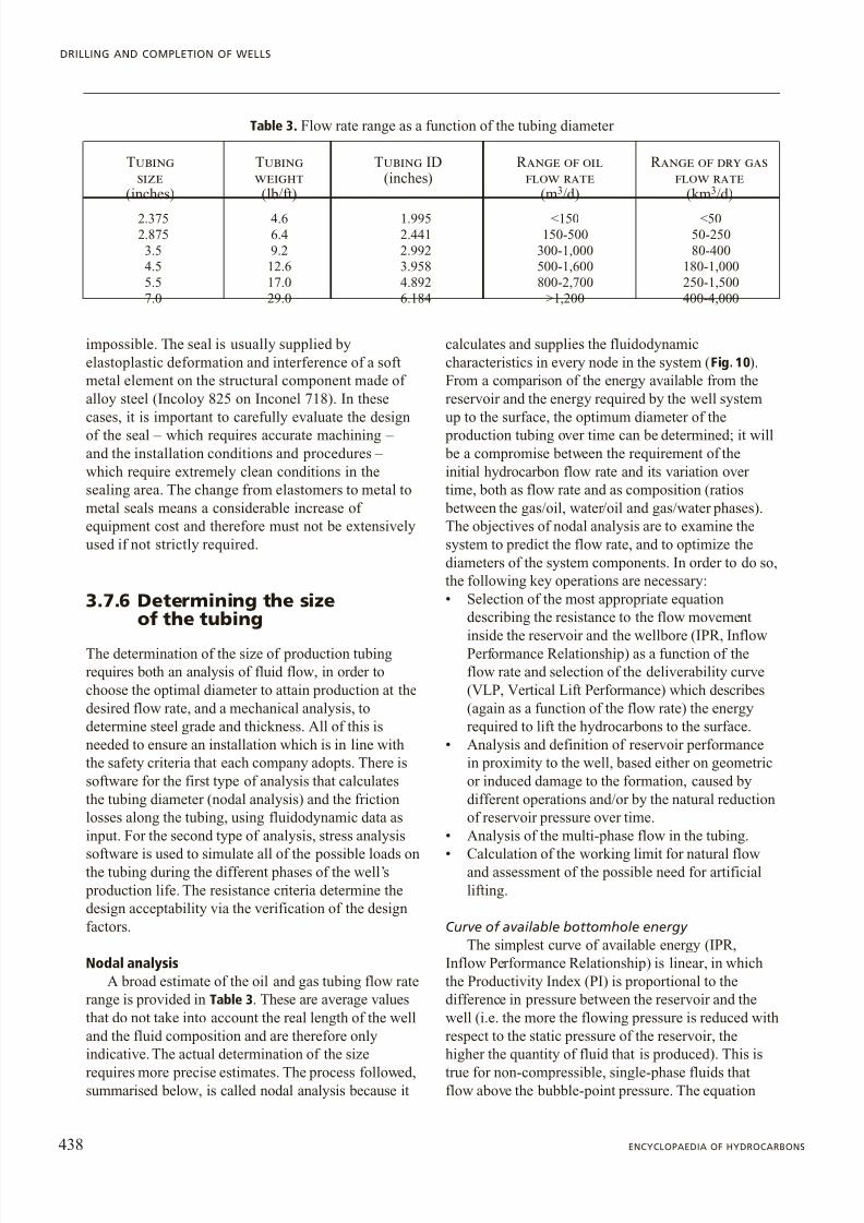
Nodal analysisA broad estimate of the oil and gas tubing flow rate
range is provided in Table 3 . These are average valuesthat do not take into account the real length of the welland the fluid composition and are therefore onlyindicative. The actual determination of the size
requires more precise estimates. The process followed,summarised below, is called nodal analysis because it
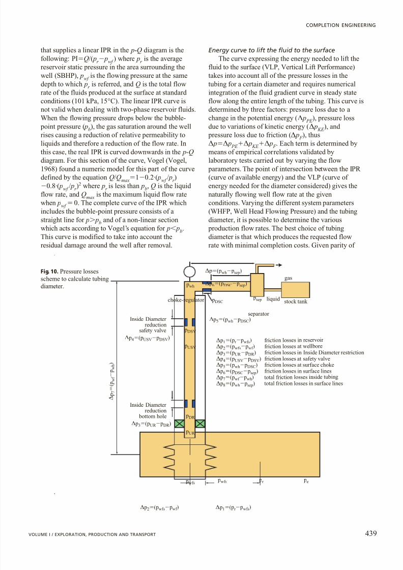
calculates and supplies the fluidodynamiccharacteristics in every node in the system ( Fig. 10).From a comparison of the energy available from thereservoir and the energy required by the well systemup to the surface, the optimum diameter of the
production tubing over time can be determined; it will be a compromise between the requirement of theinitial hydrocarbon flow rate and its variation over time, both as flow rate and as composition (ratios
between the gas/oil, water/oil and gas/water phases).The objectives of nodal analysis are to examine thesystem to predict the flow rate, and to optimize thediameters of the system components. In order to do so,the following key operations are necessary:• Selection of the most appropriate equation
describing the resistance to the flow movement
inside the reservoir and the wellbore (IPR, InflowPerformance Relationship) as a function of theflow rate and selection of the deliverability curve(VLP, Vertical Lift Performance) which describes(again as a function of the flow rate) the energyrequired to lift the hydrocarbons to the surface.
• Analysis and definition of reservoir performancein proximity to the well, based either on geometricor induced damage to the formation, caused bydifferent operations and/or by the natural reductionof reservoir pressure over time.
• Analysis of the multi-phase flow in the tubing.
• Calculation of the working limit for natural flowand assessment of the possible need for artificiallifting.
Curve of available bottomhole energyThe simplest curve of available energy (IPR,
Inflow Performance Relationship) is linear, in whichthe Productivity Index (PI) is proportional to thedifference in pressure between the reservoir and thewell (i.e. the more the flowing pressure is reduced withrespect to the static pressure of the reservoir, thehigher the quantity of fluid that is produced). This is
true for non-compressible, single-phase fluids thatflow above the bubble-point pressure. The equation
438 ENCYCLOPAEDIA OF HYDROCARBONS
DRILLING AND COMPLETION OF WELLS
Table 3 . Flow rate range as a function of the tubing diameter
Tubing Tubing Tubing ID Range of oil Range of dry gassize weight ( inches ) flow rate flow rate
(inches ) (lb/ft ) (m3/d ) (km 3/d )
2.375 4.6 1.995 <150 <502.875 6.4 2.441 150-500 50-250
3.5 9.2 2.992 300-1,000 80-4004.5 12.6 3.958 500-1,600 180-1,0005.5 17.0 4.892 800-2,700 250-1,5007.0 29.0 6.184 >1,200 400-4,000
8/13/2019 Completion Eng Pag425-450ing3
http://slidepdf.com/reader/full/completion-eng-pag425-450ing3 15/26
that supplies a linear IPR in the p-Q diagram is thefollowing: PI Q/( pr pwf ) where pr is the averagereservoir static pressure in the area surrounding thewell (SBHP), pwf is the flowing pressure at the samedepth to which pr is referred, and Q is the total flowrate of the fluids produced at the surface at standard conditions (101 kPa, 15 °C). The linear IPR curve isnot valid when dealing with two-phase reservoir fluids.When the flowing pressure drops below the bubble-
point pressure ( pb), the gas saturation around the wellrises causing a reduction of relative permeability toliquids and therefore a reduction of the flow rate. Inthis case, the real IPR is curved downwards in the p-Qdiagram. For this section of the curve, Vogel (Vogel,1968) found a numeric model for this part of the curvedefined by the equation Q/Qmax 1 0.2·( pwf / p r )
0.8 ·( pwf / p r )2 where p r is less than pb, Q is the liquid
flow rate, and Qmax
is the maximum liquid flow ratewhen pwf 0. The complete curve of the IPR whichincludes the bubble-point pressure consists of astraight line for p pb and of a non-linear sectionwhich acts according to Vogel ’s equation for p pb.This curve is modified to take into account theresidual damage around the well after removal.
Energy curve to lift the fluid to the surfaceThe curve expressing the energy needed to lift the
fluid to the surface (VLP, Vertical Lift Performance)takes into account all of the pressure losses in thetubing for a certain diameter and requires numericalintegration of the fluid gradient curve in steady stateflow along the entire length of the tubing. This curve isdetermined by three factors: pressure loss due to achange in the potential energy ( D p PE ), pressure lossdue to variations of kinetic energy ( D p KE ), and
pressure loss due to friction ( D p F ), thusD p D p PE D p KE D p F . Each term is determined bymeans of empirical correlations validated bylaboratory tests carried out by varying the flow
parameters. The point of intersection between the IPR (curve of available energy) and the VLP (curve of energy needed for the diameter considered) gives thenaturally flowing well flow rate at the givenconditions. Varying the different system parameters(WHFP, Well Head Flowing Pressure) and the tubingdiameter, it is possible to determine the various
production flow rates. The best choice of tubingdiameter is that which produces the requested flowrate with minimal completion costs. Given parity of
439VOLUME I / EXPLORATION, PRODUCTION AND TRANSPORT
COMPLETION ENGINEERING
gas
psep
D p8 (pwh psep)
D
p 7
( p
w f
p w h
)
D p7 (pwf pwh)
D p2 (pwfs pwf )
D p2 (pwf s pwf )
D p1 (p r pwfs)
D p1 (pr pwfs)
D p5 (pwh pDSC )
D p (pwh psep)
D p5 (pwh pDSC )
D p4 (pUSV pDSV )
D p4 (pUSV pDSV )
D p3 (pUR pDR )
D p3 (pUR pDR )
D p6 (pDSC psep)
D p6 (pDSC psep)
pDSC
pwh
pDSV
pUSV
pDR
pUR
pwfs pr pe pwfs
liquid
separator
choke-regulator stock tank
total friction losses in surface linestotal fri ction losses insid e tu bing
friction losses at wellboref ric tion losses in reservoir
friction losses at surface chokefriction losses at safety valvefriction losses in Inside Diameter restriction
friction losses in surface lines
Inside Diameter reduction
safety valve
Inside Diameter reduction
bottom hole
Fig. 10. Pressure lossesscheme to calculate tubingdiameter.
8/13/2019 Completion Eng Pag425-450ing3
http://slidepdf.com/reader/full/completion-eng-pag425-450ing3 16/26
the flow rate, when the tubing diameter is increased,the pressure losses diminish or given an equal
bottomhole D p, the well produces at higher flow rates.If the IPR and the VLP never meet, for the flow rateand pressure requested, the reservoir will not havesufficient energy for natural flow and thus an artif iciallift system must be installed in order to produce ateconomically viable flow rates. All of the correlationsused in calculations for both the fluids ’ PVTcharacteristics and the equations used to determine
pressure losses give valid estimates for different typesof fluids. For this reason, proper adjustment have to bemade, although too many attempts to make thecorrelations coincide with the actual data can bedetrimental. To avoid this, the data must correspond tothe measured conditions at the extremities of thesystem, i.e. at the wellhead and bottomhole.
Tubing stress analysisOnce the optimum diameter for production tubing
has been defined and the type of steel to use has beenchosen on the basis of the environment conditions, it isnecessary to verify whether the tubing can be installed in the type of well to be drilled. In other words, thecompatibility with the production casing diameter must
be verified. Then, the thickness and grade (mechanicalcharacteristics) must be defined so that they can meetthe stress conditions calculated in the various load hypotheses, and the Safety Factor (SF) set by the oil
company. The Tubing Stress Analysis (TSA) is carried out both for safety in design, i.e. by defining theminimum strength needed for well equipment(breakage of part of the completion can be harmful to
people and objects, not to mention the loss of the well production itself), and to optimise capital costs. In fact,a sizeable percentage of the well capital costs, up to 20-30% in the case of special alloys, is due to the tubular material. Therefore, by calculating the real loads, it is
possible to optimize safety factors, thicknesses and therefore costs. The TSA must be applied to all tubular material in the well and to the interaction between
tubing and casing. Generally, the tubing has theminimum critical cross section and is therefore theelement most subjected to limit loads. In reality, giventhe complexity of the downhole equipment, there may
be weakness in other completion components. In order to take this possibility into account, once the nominaldiameter, grade and thickness of the tubing are set, thespecifications of the Down Hole Equipment (DHE)require that this equipment supports at least the samelimit loads as the tubing itself.
Material properties
It is presumed that metals follow an elastic behaviour and that their yield and tensile strengths are
indicated by the symbols Y s and T s, respectively. Itshould be remembered that, aside from causingexpansion and contraction of the metal, variations intemperature determine the variation of the Y s of thematerial, which decreases as the temperature increases(in particular for CRAs and cold worked steels) and this decrease becomes larger as the number of elements in the alloy increases. The value of thethermal expansion coefficient generally used for steeltubes is: 12 ·10 6 m/(m ·°C) for carbon steel, 16 ·10 6
m/(m ·°C) per austenitic steel, 13 ·10 6 m/(m ·°C) for ferritic-austenitic steel (coefficients valid fromambient temperature up to approximately 150 °C).
The mechanical properties of Premium connectionsare normally higher than the characteristics of theassociated pipe body. They are generally not a problemfor the overall resistance of the system if – for that givenload situation – only the tubing strength is considered.There are however some limitations, such as for example compression strength. While the tube behavesin an axially symmetric manner to tension and compression, the connections often have less resistanceto compression than to tension and therefore leaks candevelop at the metal to metal seals in the case of heavycompression on the tubing.
Verification of stress is independent of thecompletion scheme, since the well, whose predominantdimension is length, requires that only the stress alongthe axis of the tube be taken into consideration. The
sections under stress are those included from thewellhead to the packer, which at setting fixes the lengthon which stress variations occur. Sections of tubing
below the packer are subjected to stress due only totheir own weight, unless they are bound between two
packers. In dual completions, the tubing sections are to be sized individually and then, according to the principle of the superposition of effects, the congruencyof the movements at the dual packer is imposed. Thereare four possible ways that tubing in the well can break:
by axial load, by internal pressure or bursting, bycollapse due to external (outer) pressure or by a
combination of loads (triaxial stress). In order to verifywhether the completion string can support the stresses,it is necessary to: identify and determine the loads towhich the string will be subjected; compare the loadswith the pipe strength (defined by API standards); and compare the real loads with the certified metal strengthvalues in combination with an adequate safety factor.This comparison is made by first defining the designfactors for the types of breakage outlined above: a) adesign coefficient for axial load (ratio between the yield stress and total calculated axial load); b) a designcoefficient for bursting (ratio between maximum burst
pressure leading to yielding and the difference betweeninternal and external pressure); c) a design factor for
440 ENCYCLOPAEDIA OF HYDROCARBONS
DRILLING AND COMPLETION OF WELLS

8/13/2019 Completion Eng Pag425-450ing3
http://slidepdf.com/reader/full/completion-eng-pag425-450ing3 17/26
collapse (ratio between the maximum collapse pressureand the difference between external and inner pressure);d ) a design factor for triaxial load (ratio between theyield strength of the materials and triaxial stress).
Load modelsThe completion scheme of a well is subject to
various loads during the working life of the well, i.e.during installation, production and pull-out. Thus, for every case, a ‘ basic case ’ is defined which is generallythe situation created – in terms of pressure,temperature, associated loads and related deformations
– when the completion is run down hole. Then, thevarious cases of load as variations of the basic casehave to be examined in sequence. It may be necessaryto take into account particular situations that may ariseover time (i.e. stimulation with acid solutions,formation fracturing, wellhead shut-in, etc.).
The logical sequence of calculation requiresstarting with a completion with the tubing anchored tothe packer and that this layout, the absolute safest, is
progressively modified only if the calculation fails,eventually arriving to a solution in which the tubing is
partially or totally free to move with respect to the packer.
Definition of loadsOnce the system geometry (depth, deviations,
diameters) has been determined, it is not only
necessary to define the pressure and temperature of the initial case – for which direct measurements aregenerally available – but also to generate load casesfor the entire well production life. It is thereforeimportant to list the operations that will be carried outin the well, to generate pressure and temperatures
profiles along the entire length of the production string(by nodal analysis) and to use these profiles tocalculate the stress induced on the tubing.
The main load situation that may arise are:Completion installation . The loads exerted in this
phase are due to pressure tests and tubing ’s own
weight. The basic case predicts the condition of thetubing run in hole with the packer at its lower end.During completion installation, the tubing is heated tothe ambient well temperature according to the welltemperature profile. As such the tubing is not affected
by temperature but only by pressure. The firstvariation during the running is thus pressurization atthe packer setting; the packer, once set to the casingwall, stops any further lengthening of the tubing.
Acid stimulation, fracturing . Stimulations arecarried out to remove damage or improve formation
permeability. Acid stimulation consists of the injection
of a known quantity of liquid (acid solutions) withhigh flow rate and high pressure (with variations of
friction and cooling of the string). Hydraulic fracturingleads to the exasperation of stress due to thestimulation: the volumes injected, the injection rates,the times and pressure reached during fracturing, in
particular before fracture formation, are thusincreased.
Wellhead shut-in . This operation involves a rise inwellhead pressure, since bottomhole pressure tends toreturn to the values of reservoir static pressure and – since the fluid pressure gradient is certainly lower thanone (presence of two phases or only gas) – a residualincrease in shut-in pressure is generated at thewellhead. This load condition must be considered since the temperature reached at the wellhead during
production does not fall immediately, as aconsequence of the thermal inertia in the well, and therefore the load condition relevant to thetemperature is similar to that during production, butwith greater wellhead pressure.
Completion pull-out . This is the condition thatexpresses the pull tension that must be applied to thetubing to release it from the packer itself or to releasethe packer during the pulling out for workover and which depend on the type of packer installed.
Considering installation of the completion and packer setting as the basic case, the other typical load situations to production wells are: a) opening of thewell for production (test and stimulation); b) long-term
production; c) shut-in; d ) completion pull-out
(releasing tubing from the packer or releasing the packer); e) other planned operations (artificial lift,successive stimulations, etc.); f ) stress on the
production casing due to temperature variations (if notcompletely cemented). For injection wells, in additionto completion installation and packer setting, the other load situations are: a) beginning of injection (test and stimulations); b) long-term injection; c) reopening of the well to injection after a shut-in; d ) stress on the
production casing due to temperature variations (if notcompletely cemented); e) completion pull-out. Asstated above, stress must be verified in axial, radial
and tangential directions (API standards only giveindications on the individual loads applied and do notconsider combinations of loads). The typical approachis thus both to determine the stresses in the threedirections (axial, radial and tangential) and to comparethem with the values indicated by API, as well as toverify the composite stress (triaxial stress).
While the formulae used in determining stress arenot given here, it is worth highlighting the effect of axial loads. If the tube is free to move, pressure and temperature variations only give rise to variations inlength. If, instead, the tube is fixed, the axial force is
the sum of the forces that would exist if the tube werefree and the forces generated by the resistance of the
441VOLUME I / EXPLORATION, PRODUCTION AND TRANSPORT
COMPLETION ENGINEERING
8/13/2019 Completion Eng Pag425-450ing3
http://slidepdf.com/reader/full/completion-eng-pag425-450ing3 18/26
anchorage to deformation. Generally, the movement isfirst calculated as though the tube were free and thenthe forces to bring it back to the initial position aredetermined (or at least to the position of anchorage),also taking any instability due to buckling intoaccount. This method makes it possible to evaluate themovement of a mobile seal within the packer when thetubing-packer connection is free and thus to determinethe length of the seal elements to install or, in the caseof an anchored tubing-packer connection, to establishthe pull that the contracting/elongating tubing exertson the packer and therefore on the casing. At this
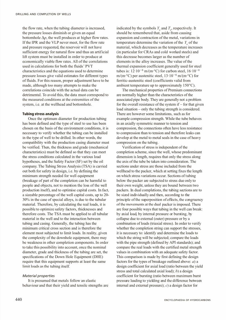
point, it is worth mentioning the curving of the tubinginto a helix due to buckling load, because of the factthat in this case the deformation is limited by the
presence of the casing. This makes it possible to reacha higher grade of instability ( Fig. 11). The buckling of the production string can be tolerated in many casesfrom a static point of view if the tensions areacceptable. Still, it should be verified that this does notlead to other problems, such as those related to:
blockage of the passage of equipment lowered
downhole by wireline; or metal to metal connectionseal loss if the bending is excessive. There are specificformulae to determine the maximum diameters of theinstruments and the length of the equipment that cango through a section of tubing under bucklingconditions. It is however possible to mitigate or eliminate the effects of buckling by increasing the
pressure in the production annulus, since this tends tostraighten the tubes.
Design tensions and maximum admissible tensionsThe so-called Design Factor (DF) is the ratio
between yield tension and real tension (calculated)in one section of the structure, while the SafetyFactor (SF) is the ratio between yield tension and maximum admissible tension (normally set by theoil company). The result of the TSA of a tubingstring is the evaluation of the design factors in all of the completion sections for all load conditions
predicted throughout the life of the well (includingabandonment or workover). The process may requirerepeated calculations in the event of unsatisfactoryresults (the DF must be greater than or equal to theSF) or when various alternatives are analysed inorder to establish the most advantageousconfiguration in terms of cost/benefits. From acomparison of the DF, the SF and the acceptance of the values calculated for all tubing sections, it is
possible to determine: the forces exchanged between
the tubing and the packer; the forces exchanged between the packer and the casing; and the packer strength, verifying the loads calculated on itscharacteristic curve that indicates the maximum load supported by the packer (this characteristic curve issupplied by the manufacturers and/or determined experimentally). The SFs normally acceptable arefixed by the oil company. Should the calculationresult in a DF less than the minimum required SF,modifications of the configuration must beintroduced and the calculations repeated.Modifications may involve: a) a higher grade of
steel (verifying the limitations of use in the presenceof H 2S when grades of over 80,000 psi or 655 MPa(L80) are required); b) an increase in the pipethickness (section increase, noting however that inthis case, the pipe weight and pressure also increaseand the temperatures of the fluid produced/injected changes, thus making it necessary to repeat thefluidodynamical calculations); c) use a pull or astack off of the tubing on the packer or change the
packer (or the packer setting mechanism); d ) the useof a smaller production casing in the case of large
buckling of the tubing. On the other hand, should the
problems of the system only be caused by particular operations like stimulation or fracturing, which
442 ENCYCLOPAEDIA OF HYDROCARBONS
DRILLING AND COMPLETION OF WELLS
F
M f
M t
F
a
neutral point
Fig. 11. Helical buckling of the tubing. M f , moment of flexion; M t , moment of torsion;
a , angle of the helix of deformation .
8/13/2019 Completion Eng Pag425-450ing3
http://slidepdf.com/reader/full/completion-eng-pag425-450ing3 19/26
cause high contraction due to cooling, action can betaken by heating the injected fluid or increasing the
pressure in the production annulus.
3.7.7 Choosing packer type,setting method andtubing-packer connection
The integral type tubing-packer connection providesthe greatest structural and seal guarantees. However,the selection of the type of packer, having taken intoaccount tension analysis results, is the result of severalcompromise solutions. In order to select the type of
packer to be used, the type of well where it is to beinstalled is evaluated. A distinction is made between;a) very critical wells, those with True Vertical Depths(TVDs) of over 4,500 m, with high temperatures(SBHT, Static Bottom Hole Temperature, of over 130°C) and high pressure (SBHP, Static Bottom HolePressure, greater than 700 atm), subsea wells, thosewith platforms on shipping lines (transit lines of commercial maritime traffic) and high-pressure gas-injection wells (over 210 atm); b) very critical and corrosive wells, those with the characteristics defined in point a but producing highly corrosive fluids; c)critical wells, those with a SBHT of between 100 °Cand 130 °C and a depth between 3,000 and 4,000 m(TVD); d ) non-critical wells, those with a SBHT of
below 100 °C and a depth lower than 3,000 m (TVD).The general approach is to use simple completionschemes in the more complex and critical situations,and then, in very corrosive and critical wells, to usetested equipment of guaranteed reliability withoutalternative daring operating solutions that may failduring the working life of the well.
The selection criteria also take into consideration aseries of parameters for each well category. Such
parameters can be related to: the procedure (for example, the use of perforation systems, by means of guns run downhole and activated once production
packers are set, provoke mechanical shock); the typeof completion fluid used (if a completion fluid containing solids in suspension is used, the use of retrieval packers is critical since their releasemechanisms can be blocked over time by the depositof solids); or the life of the completion because of frequent pulling out of the tubing and the productionstring with the packer.
The design scheme followed in very critical wellsis as follows: first, choice of the packer, then thechoice of the tubing-packer connection and finally of the method of packer setting. The criterion is similar to
that for other well categories where the installationoperations and the type of fluid used are different.
Single completionsIn very critical wells, a permanent packer is chosen
because it supplies the best mechanical and seal performance. In very corrosive wells, a permanent-retrievable packer is used because the corrosivity of the system may require its removal during the
production life. If a permanent-retrievable packer made of the adequate CRA steels is chosen, theretrieval can be planned without milling, consideringthat the milling for permanent packers is timeconsuming when they are made of chrome-nickel steelalloys. For critical and very critical wells, the hydraulic
packer setting method is the best solution. The reasonfor this choice lies in the fact that the packer isgenerally run downhole with the production tubingand therefore, in order to avoid problems related todeposit in the annulus, a filtered fluid not containingsolids in suspension and of adequate density iscirculated in the annulus before setting. At this point,the system is ready for hydraulic setting which iscarried out after the installation of a wireline plug
below the packer. The two aspects that need to betaken into consideration for the tubing-packer connection are the choice of the tubing-packer connection and the predicted tensions. In very criticalor corrosive wells, first the anchored tubing is chosen:the choice is made between an anchored system and asnap latch system capable of separating at a pre-determined load. If the TSA shows that DF SF, i.e. if
the connection holds in all load situations, acompletely anchored system is chosen. If, instead, theanalysis indicates that DF SF and the connectiontends to release, for example during stimulation, asnap latch system is used with a mobile seal element(PBR) that only starts functioning in critical cases (for example, cooling and contraction due to stimulation).The entire process must be re-verified and should the
production still indicate DF SF, a totally mobilesystem with mobile seals must be chosen. In this lastcase, since there is a free connection, the packer running and setting methods must also been
reconsidered. If this choice is made, there are no other verification problems since a free connection is alwaysverified. The analysis is also used to determine thetubing elongation/contraction and therefore the lengthof the seals to be chosen. Other well categories requiresimilar considerations – ranging from packer settingmethods to methods for level perforation – to take intoaccount how the guns are run downhole and the loadsthey employ, as well as the composition of fluids and their solids content.
Selective completions
The considerations outlined below can be applied to selective completions with two or more productive
443VOLUME I / EXPLORATION, PRODUCTION AND TRANSPORT
COMPLETION ENGINEERING

8/13/2019 Completion Eng Pag425-450ing3
http://slidepdf.com/reader/full/completion-eng-pag425-450ing3 20/26
levels and give an indication of the various possibilitiesin selecting the packers and their setting methods,
based on the critical elements described in the wellclassification. The case of a dual completion has beenillustrated, but it is clear that in the presence of multiple levels, the lower packer is the first startingfrom the bottom while the upper packers are all thesame. When conditions of criticality are not applied,selection is based on the predicted setting depth. Infact, the greater the depth, the less suitable the use of mechanical packer setting methods that requiremanipulation of the tubing string as well as multipleruns for multiple completions. The setting method depends mainly on the distance between packers.Wireline set mechanical packers (with explosivecharges) are generally placed very precisely since thedepth is controlled by the depth recordings whilerunning. They are only used as bottom packers becausethey require a dedicated run, followed subsequently bythe tubing running with all upper packers. If
permanent packers are used, hydraulic setting for allthe packers is preferable. When the lower packer is
permanent, the upper packers are retrievable and brineis the completion fluid, the safest method is hydraulicsetting for all the upper packers, while the lower
packer is set by means of a wireline. When all of the packers are retrievable, hydraulic setting is advisableand, in this case, the distance between the packers must
be at least 50 m. This distance takes into account the
elasticity required by the relative movements betweenthe packer components that generally tend to scrapethe section of tubing above the packer during setting
(with shorter distances, the mechanical anchoring and the sealing can be compromised because of anincomplete setting stroke). As regards the tubing-
packer connection scheme, the choice of the upper connection is based on calculation of the tensionsapplied to the single completion, while the subsequentconnections are chosen on the basis of differentcriteria. In general, anchored connections are used when all of multiple packers are run-in hole together,while mobile connections are used when each packer isrun individually, and then reintegrates the packer already in the well.
3.7.8 Tubing hanger selection
Together with the tubing spool , the tubing hanger isthe element that joins the drilling wellhead and thechristmas tree ( Fig. 12). The vertical crossrun of thechristmas tree has the same dimensions as the
production tubing since the connection size of thetubing and the tubing hanger Inside Diameter must becompatible. In particular, the inside of the tubinghanger must be larger than the production tubingInside Diameter because it contains the first nipple for wireline equipment, generally dedicated to the back
pressure valve. This valve is installed as a primarysafety barrier during the BOP installation and removal
phases when the well is completed. The choice of steel
for the tubing hanger is consistent with that of thetubing, in particular, since it is made from a forged bar, it is normally of nobler material than the
444 ENCYCLOPAEDIA OF HYDROCARBONS
DRILLING AND COMPLETION OF WELLS
gate valve
tubing hanger metal seal
metal seal
swagelock
new vam
test port
autoclave valve 15,000 psi
test port
vent port
back pressure valvetubing head adapter tubing head spooltie down
gate valvecontrol line
Fig. 12. Tubing hanger.

8/13/2019 Completion Eng Pag425-450ing3
http://slidepdf.com/reader/full/completion-eng-pag425-450ing3 21/26
corresponding tubing. The tubing hanger is located inthe tubing spool, which has special shoulders of sufficient size to support the maximum weight and
pressure loads of the tubing string. Here, it is blocked mechanically inside the tubing spool by radial means(tie-down) or, more recently, with elastic snap rings.
The connection to the production tubing involvesthe premium thread of the production tubing itself with metal to metal seals, while the link with thechristmas tree requires metal to metal seals that can bea transition type carrier (Laurent carrier). Tubinghanger to tubing spool seals are normally elastomeric,while only in the case of high pressure and temperature wells (15,000-20,000 psi, T 100 °C)metal to metal seals are used. The tubing hanger isalso used to support and provide outside links to thehydraulic control lines of the Surface Controlled Subsurface Safety Valve (SCSSV). In the case of horizontal wellheads, the tubing hanger has a differentlayout with the flow outlets in a horizontalconfiguration, while on the vertical run, above the sideexit, there are wireline profiles which support themetal-to-metal seal wireline plugs that act as primary
barriers. In the case of wells which are pumped byElectric Submersible Pumps (ESPs), the tubing hanger must also support the electric mandrel that interruptsthe electric cable to facilitate assembly duringcompletion installation and which works as a safety
barrier during production. As far as the choice of
accessories is concerned, see Chapter 3.5.
3.7.9 Subsea completions
Subsea completions use downhole equipment that issimilar to that used on land/offshore wells, but differ with respect to the equipment placed on the sea floor.The hydrocarbons produced by isolated and/or grouped wells are conveyed to a manifold system,designed to handle different flows from productionwells or destined to injection wells.
In a production system with a riser (see Chapter 5.2), the latter is used to transport hydrocarbonsfrom the manifold system to a surface structure thatmay be a fixed platform, a semi-submersible
platform or an anchored ship, modified to receivefluids on board and possibly serve as a loadingterminal for oil tankers. As mentioned elsewhere(see Chapters 5.2 and 5.4), the hydrocarbonsundergo treatment at the surface in order to achievethe transport specifications (degassing, water removal, desulphurisation, etc.). Subsequently, theyare transferred into tankers, in the case of oil, or sent
back to the sea floor, being pumped into subsea pipelines.
The conventional subsea wellhead system(Fig. 13) involves the use of a christmas tree with avalve configuration similar to that of a surfacechristmas tree for dual completion. The vertical
penetration with larger diameter (production bore) isdedicated to the tubing, while the other vertical
penetration is used to control the production annulus.During the completion phase, the well is linked to thesurface rig by means of an environmental productiontube that isolates it from the sea (marine riser). Theriser is tensioned between the rig and the subseaBlow Out Preventer group (BOP stack) which is used to guarantee the continuity of the well from the seafloor to the surface. When the tubing hanger – containing two vertical holes – is installed at the end of completion, it is run downhole with the tubinghanger running tool and the production riser and
placed inside the drilling wellhead, in its dedicated recess. The production riser consists of sections
joined to each other with rapid connectors and eachsection includes two lines of tubes: the actual tubingand the annulus line. This allows control of thecirculation between the annulus and the tubing fromthe surface, even with the hanger landed in its resting
position. A flexible, umbilical line is banded to the production riser during running and contains a seriesof lines for passage of the fluid for hydraulic control,fluid allowing remote control of the setting and testing functions of the tubing hanger and of the
release of the production riser from the tubinghanger. After running, setting and testing of thetubing hanger, the next step is the installation and setting of the wireline plugs placed inside the tubinghanger inside each line of tubing of the productionriser. These wireline plugs, together with the wellsafety system, act as the safety barrier duringremoval of the BOP and drilling riser system until theinstallation of the subsea christmas tree is completed.One of the functions of the umbilical is the release of the tubing hanger running tool from the tubinghanger when at the surface and this will allow the
subsequent pull out of the production riser, which isretrieved section by section. The BOP stack is thendisconnected from the wellhead and pulled outtogether with the drilling riser. At the surface, thesubsea christmas tree and workover control packageare assembled and tested, and the entire group isagain run using the production riser and theumbilical. Once the equipment has reached the seafloor and is aligned with the christmas tree, it islanded and connected to the drilling wellhead, thehydraulic connectors are closed and all the pressureand functionality tests are performed. At this point,
the christmas tree is ready for working. The wireline plugs are extracted from the two prof iles in the
445VOLUME I / EXPLORATION, PRODUCTION AND TRANSPORT
COMPLETION ENGINEERING
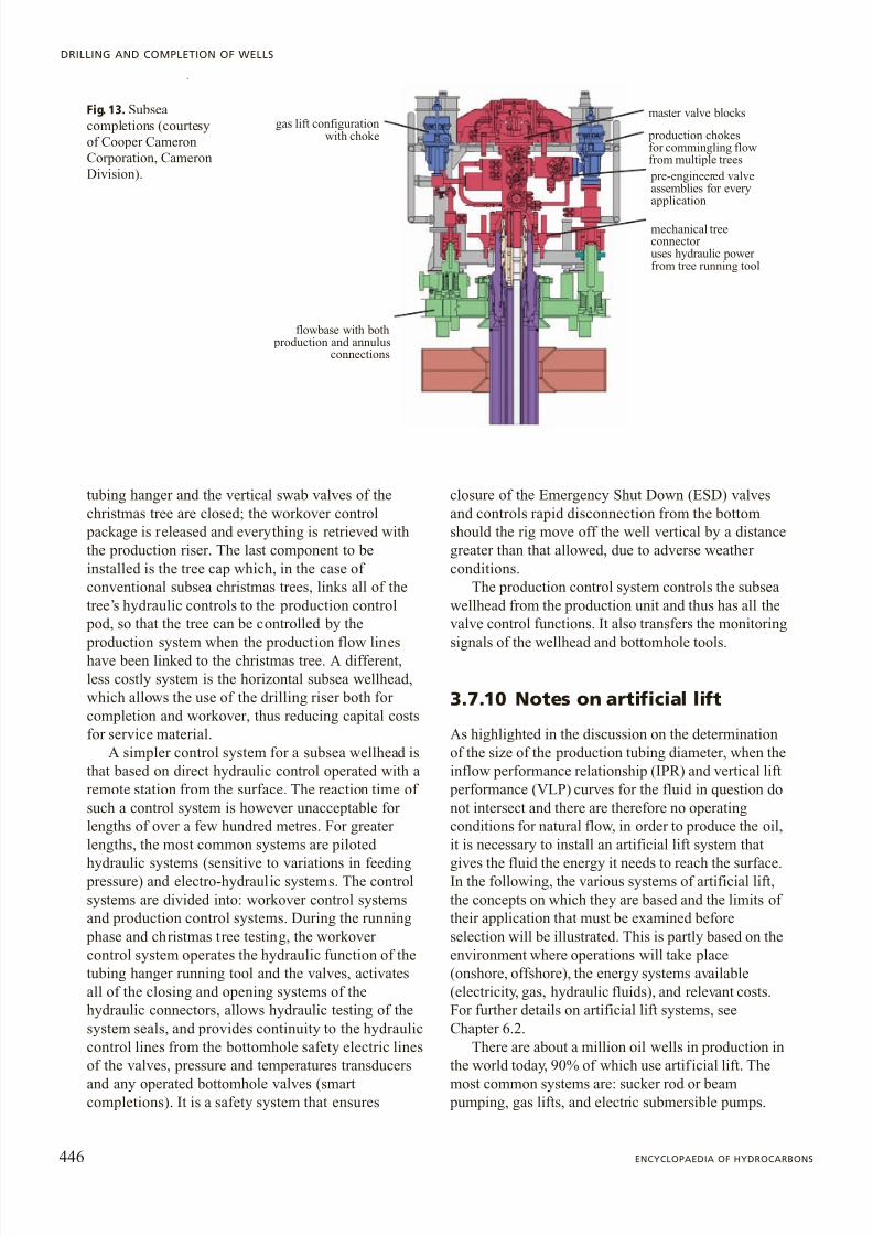
8/13/2019 Completion Eng Pag425-450ing3
http://slidepdf.com/reader/full/completion-eng-pag425-450ing3 22/26
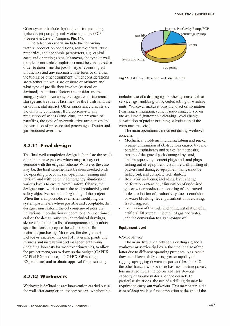
8/13/2019 Completion Eng Pag425-450ing3
http://slidepdf.com/reader/full/completion-eng-pag425-450ing3 23/26
Other systems include: hydraulic piston pumping,hydraulic jet pumping and Moineau pumps (PCP,Progressive Cavity Pumping; Fig. 14).
The selection criteria include the followingfactors: production conditions, reservoir data, fluid
properties, and economic parameters, e.g. capitalcosts and operating costs. Moreover, the type of well(single or multiple completion) must be considered inorder to determine the possibility of commingled
production and any geometric interference of either the tubing or other equipment. Other considerationsare whether the wells are onshore or offshore and what type of profile they involve (vertical or deviated). Additional factors to consider are theenergy systems available, the logistics of transport,storage and treatment facilities for the fluids, and theenvironmental impact. Other important elements arethe climatic conditions, fluid corrosivity, any
production of solids (sand, clay), the presence of paraffins, the type of reservoir drive mechanism and the variation of pressure and percentage of water and gas produced over time.
3.7.11 Final design
The final well completion design is therefore the resultof an interactive process which may or may notcoincide with the original scheme. Whatever the case
may be, the final scheme must be crosschecked withthe operating procedures of equipment running and retrieval and with potential emergency situations atvarious levels to ensure overall safety. Clearly, thedesigner must work to meet the well productivity and safety objectives set at the beginning of the project.When this is impossible, even after modifying thesystem parameters where possible and acceptable, thedesigner must inform the oil company of possiblelimitations in production or operations. As mentioned earlier, the design must include technical drawings,sizing calculations, a list of components and product
specifications to prepare the call to tender for materials purchasing. Moreover, the design mustinclude estimates of the cost of materials, plants and services and installation and management timing(including forecasts for workover timetable), to allowthe project managers to draw up the budget (CAPEX,CAPital EXpenditure, and OPEX, OPeratingEXpenditure) and to obtain approval for purchasing.
3.7.12 Workovers
Workover is def ined as any intervention carried out inthe well after completion, for any reason, whether this
includes use of a drilling rig or other systems such asservice rigs, snubbing units, coiled tubing or wirelineunits. Workover makes it possible to act on formation(washing, stimulation, cement squeezing, etc.) or onthe well itself (bottomhole cleaning, level change,substitution of packer or tubing, substitution of thechristmas tree, etc.).
The main operations carried out during workover concern:• Mechanical problems, including tubing and packer
repairs, elimination of obstructions caused by sand, paraffin, asphaltenes and scales (salt deposits),repairs of the gravel pack damaged by sand,cement squeezing, cement plugs and sand plugs,fishing out of equipment lost in the well, milling of
packers and damaged equipment that cannot befished out, and complete well shutoff.• Reservoir problems, including level change,
perforation extension, elimination of undesired gas or water production, opening of obstructed holes, reduction of productivity due to emulsionor water blocking, level partialization, acidizing,fracturing, etc.
• Conversion of the well, including installation of anartificial lift system, injection of gas and water,and the conversion to a gas storage well.
Equipment used
Workover rigsThe main difference between a drilling rig and a
workover or service rig lies in the smaller size of thelatter due to different operating purposes. As a resultthey entail lower daily costs, greater rapidity of rigging-up/rigging-down/transport and less bulk. Onthe other hand, a workover rig has less hoisting power,less installed hydraulic power and less stowagecapacity of tubular material on the derrick. In
particular situations, the use of a drilling rig may be
required to carry out workovers. This may occur in thecase of deep wells, a first completion at the end of the
447VOLUME I / EXPLORATION, PRODUCTION AND TRANSPORT
COMPLETION ENGINEERING
Progressive Cavity Pump, PCPcentrifugal pump
others
rod pump
hydraulic pump
gas lift
Fig. 14. Artificial lift: world wide distribution.
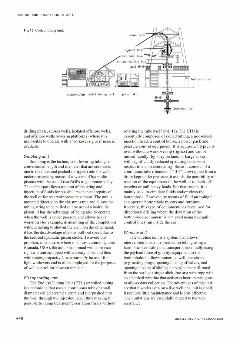
8/13/2019 Completion Eng Pag425-450ing3
http://slidepdf.com/reader/full/completion-eng-pag425-450ing3 24/26
drilling phase, subsea wells, isolated offshore wells,and offshore wells (even on platforms) where it isimpossible to operate with a workover rig or if none isavailable.
Snubbing unit Snubbing is the technique of lowering tubings of
conventional length and diameter that are connected one to the other and pushed (stripped) into the well
under pressure by means of a system of hydraulic pistons with the use of two BOPs to guarantee safety.The technique allows rotation of the string and injection of fluids for possible mechanical repairs of the well or for reservoir pressure support. The unit ismounted directly on the christmas tree and allows thetubing string to be pulled out by use of a hydraulic
piston. It has the advantage of being able to operatewhen the well is under pressure and allows heavyworkover (for example, dismantling of the completion)without having to shut-in the well. On the other hand,it has the disadvantage of a low pull-out speed due to
the reduced hydraulic piston stroke. To avoid this problem, in countries where it is most commonly used (Canada, USA), the unit is combined with a servicerig, i.e. a unit equipped with a rotary table, and thuswith rotating capacity. It can normally be used for light workovers and is often employed for the purposesof well control for blowout remedial.
ETU operating unit The Endless Tubing Unit (ETU) or coiled tubing
is a technique that uses a continuous tube of smalldiameter coiled around a drum and run/pushed into
the well through the injection head, thus making it possible to pump treatment/circulation fluids without
rotating the tube itself ( Fig. 15). The ETU isessentially composed of coiled tubing, a gooseneck injection head, a control house, a power pack and
pressure control equipment. It is equipment typicallyused without a workover rig (rigless) and can bemoved rapidly (by lorry on land, or barge at sea),with significantly reduced operating costs withrespect to a conventional rig. Since it consists of acontinuous tube (diameter 1''-3.5'') unwrapped from a
drum kept under pressure, it avoids the possibility of rotation of the equipment in the well or to slack off weights or pull heavy loads. For that reason, it ismainly used to circulate fluids and/or clean the
bottomhole. However, by means of fluid pumping itcan operate bottomhole motors and turbines.Recently, this type of equipment has been used for directional drilling where the deviation of the
bottomhole equipment is achieved using hydrauliccontrol lines run inside the coil.
Wireline unit
The wireline unit is a system that allowsintervention inside the production tubing using aharmonic steel cable that transports, essentially usingthe payload force of gravity, equipment to the
bottomhole. It allows numerous well operations(e.g. setting plugs, opening/closing of valves, and opening/closing of sliding sleeves) to be performed from the surface using a slick line or a wire rope withan electrical wireline that activates instruments, gunsor allows data collection. The advantages of this unitare that it works even on a live well, the unit is small,it requires little maintenance and is cost effective.
The limitations are essentially related to the wireresistance.
448 ENCYCLOPAEDIA OF HYDROCARBONS
DRILLING AND COMPLETION OF WELLS
control cabin coiled tubing reel power skid BOP
christmas tree
lubricator/riser
goose neck
hydraulic hose
stripper/stuffing box
quad BOPs
injector head
Fig. 15. Coiled tubing unit.
8/13/2019 Completion Eng Pag425-450ing3
http://slidepdf.com/reader/full/completion-eng-pag425-450ing3 25/26
Bibliography
API (American Petroleum Institute) (1994) Bulletin on formulasand calculation for casing, tubing, drill pipe & line pipe
properties , API Bul 5C3.API (American Petroleum Institute) (2000) Specification for
subsurface safety valve equipment , API Spec 14A.API (American Petroleum Institute) (2001) Specification for
casing & tubing , API Spec 5CT.ASTM (American Society for Testing and Materials) (2002)
Specification for mechanical testings of steel products ,ASTM A 370.
Harper C.A. (2002) Handbook of plastics, elastomers and composites , New York, McGraw-Hill.
ISO (International Organization for Standardization) (2000) Petroleum and natural gas industries. Corrosion resistant alloys seamless tubes for use as casing, tubing and coupling
stock , ISO 13680.ISO (International Organization for Standardization) (2001)
Petroleum and natural gas industries. Downhole equipment. Packers and bridge plugs , ISO 14310.
ISO (International Organization for Standardization) (2002) Petroleum and natural gas industries. Procedures for testing casing and tubing connections , ISO 13679.
ISO (International Organization for Standardization) (2004) Petroleum and natural gas industries. Subsurface safetyvalve systems. Design, installation, operation and repair ,ISO 10417.
Magarini P.A. et al. (2000) Best practices & minimumrequirements . Sec 1 , Eni-STAP.
NACE (National Association of Corrosion Engineering) (1996) Laboratory testing of metals for resistance to sulfide stresscracking in H 2 S environments , NACE TM 0177 96.
SINTEF (Scientific and Industrial Research at the NorvegianInstitute of Technology) (2002) Reliability of well completionequipment. Phase IV , SINTEF-Eni.
References
API (American Petroleum Institute) (2004) Specification for wellheads and Christmas tree equipment , API 6A.
ISO (International Organization for Standardization) (2003) Petroleum and natural gas industries. Drilling and production equipment. Wellhead and Christmas treeequipment , ISO 10423.
NACE (National Association of Corrosion Engineering) (2001)Sulfide stress cracking resistant metallic material for oilfield equipment , NACE MR 01 75.
Vogel J.V. (1968) Inflow performance relationships for solution gas drive wells , «Journal of Petroleum Technology », January,83-92.
Marco MarangoniScientific Consultant
449VOLUME I / EXPLORATION, PRODUCTION AND TRANSPORT
COMPLETION ENGINEERING

8/13/2019 Completion Eng Pag425-450ing3
http://slidepdf.com/reader/full/completion-eng-pag425-450ing3 26/26