muon collider targetry r&d
TRANSCRIPT
Muon Collider Targetry R&D
[http://www.hep.princeton.edu/mumu]
K.T. McDonald
Princeton U.
May 1, 1998
Muon Collider Targetry Workshop
Brookhaven National Laboratory
1

Overview of Targetry
• Get muons from pion decay: π± → μ±ν.
• Pions from proton-nucleus interactions in a target.
• Goal: 1.2 × 10¹⁴ μ±/s.
• ⇒ High-Z target,
High-energy proton beam,
High magnetic field around target to capture soft pions.
• μcollider/ptarget ≈ 0.08 ⇒ 1.5 × 10¹⁵ p/s at 16 GeV.
• 15-Hz proton source.
• 4 MW power in p beam.
• Compare: 0.1 MW in 900-GeV extracted p beam at FNAL;
0.25 MW in 30-GeV extracted beam at BNL AGS.
• Target should be short, narrow and tilted to minimize π loss.
• ⇒ No cooling jacket.
• High power of beam would crack stationary target (or pipe).
• ⇒ Pulsed heavy-metal liquid jet as target.
2

Baseline Scenario
• Liquid metal target: Ga/In, Hg, or solder (Bi/In/Pb/Sn alloy).
• 20-T capture solenoid followed by 5-T phase-rotation channel.
• 20 T = 6-T, 8-MW water-cooled Cu magnet
+ 14-T superconducting magnet.
• Cost of 14-T magnet ≈ 0.8 M$ (B[T] R[m])1.32(L[m])0.66
= 0.8 M$ (14[T] 0.6[m])1.32(0.75[m])0.66 ≈ $11M.
3

• Capture pions with P⊥ < 220 MeV/c.
• Adiabatic invariant: Φ = πr2B as B drops from 20 to 5 T.
• r = P⊥/eB = radius of helix.
• ⇒ P⊥,f = P⊥,i
√Bf/Bi = 0.5P⊥,i (and P‖,f > P‖,i).
Yield vs. Beam Energy Yield vs. Magnetic Field
5 10 15 20 25 30Proton beam energy (GeV)
0.2
0.4
0.6
0.8
1.0
Mes
on y
ield
(0.
05<
p<0.
8 G
eV/c
) pe
r pr
oton
Protons on 1.5λ untilted target20 T solenoid (ra=7.5 cm) MARS13(97) 8−Dec−1997
π++K
+, Ga (L=36.3cm, R=3+0.2cm), σ=1cm
π−+K
−, Ga (L=36.3cm, R=3+0.2cm), σ=1cm
π++K
+, Ga (L=36.3cm, R=1cm), σ=0.4cm
π−+K
−, Ga (L=36.3cm, R=1cm), σ=0.4cm
π++K
+, PtO2 (L=26.85cm, R=1cm), σ=0.4cm
π−+K
−, PtO2, (L=26.85cm, R=1cm), σ=0.4cm
0 5 10 15 20 25 30Solenoid field B (T)
0.0
0.1
0.2
0.3
0.4
0.5
0.6
0.7
Mes
on y
ield
(0.
05<
p<0.
8 G
eV/c
) pe
r pr
oton
16 GeV proton beam (σx=σy=4 mm) on Ga target (L=72.6cm, r=1cm)Tilt angle α=150 mrad MARS13(98) 14−Mar−1998
Y(π+ + K
+)
Y(π− + K
−)
YC(π+ + K
+)
YC(π− + K
−)
B×Ra
2 = 1125 T×cm
2
Yield vs. Target Radius Yield vs. Target Angle
0 1 2 3Target radius (cm)
0.2
0.3
0.4
0.5
0.6
Mes
on y
ield
(0.
05<
p<0.
8 G
eV/c
) pe
r pr
oton
16 GeV proton beam on Ga (L=72.6cm, R=RGa+tSS). Tilt angle α=100 mradtSS=0.5mm at R<0.75cm, =1mm at R>0.75cm MARS13(98) 27−Apr−1998
Y(π+ + K
+)
Y(π− + K
−)
YC(π+ + K
+)
YC(π− + K
−)
B=20 T, Ra=7.5 cm
R=2.5σx,y
0 50 100 150 200Tilt angle α (mrad)
0.3
0.4
0.5
0.6
Mes
on y
ield
(0.
05<
p<0.
8 G
eV/c
) pe
r pr
oton
16 GeV proton beam (σx=σy=4 mm) on Ga target (r=1cm)Solenoid B=20 T, Ra=7.5 cm MARS13(98) 14−Mar−1998
Y(π+ + K
+)
Y(π− + K
−)
YC(π+ + K
+)
YC(π− + K
−)
L = 72.6 cm
Ra at 200 m
8.5
8.5
7.5
7.5
4
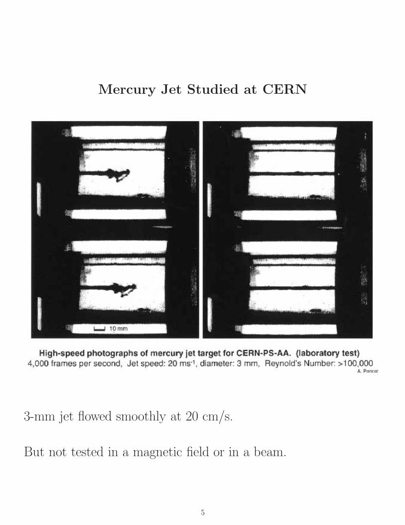
Mercury Jet Studied at CERN
3-mm jet flowed smoothly at 20 cm/s.
But not tested in a magnetic field or in a beam.
5
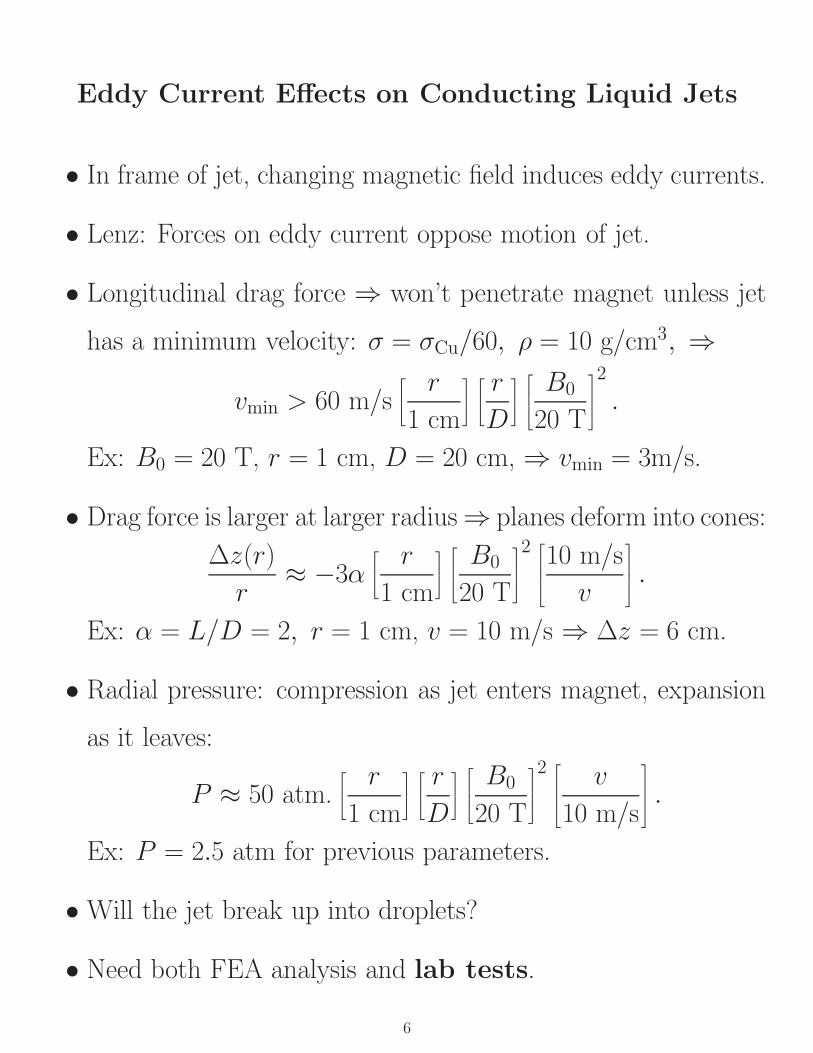
Eddy Current Effects on Conducting Liquid Jets
• In frame of jet, changing magnetic field induces eddy currents.
• Lenz: Forces on eddy current oppose motion of jet.
• Longitudinal drag force ⇒ won’t penetrate magnet unless jet
has a minimum velocity: σ = σCu/60, ρ = 10 g/cm3, ⇒
vmin > 60 m/s⎡⎣ r
1 cm
⎤⎦
⎡⎣ r
D
⎤⎦
⎡⎢⎣
B0
20 T
⎤⎥⎦2
.
Ex: B0 = 20 T, r = 1 cm, D = 20 cm, ⇒ vmin = 3m/s.
• Drag force is larger at larger radius ⇒ planes deform into cones:
Δz(r)
r≈ −3α
⎡⎣ r
1 cm
⎤⎦
⎡⎢⎣
B0
20 T
⎤⎥⎦2 ⎡
⎢⎢⎣10 m/s
v
⎤⎥⎥⎦ .
Ex: α = L/D = 2, r = 1 cm, v = 10 m/s ⇒ Δz = 6 cm.
• Radial pressure: compression as jet enters magnet, expansion
as it leaves:
P ≈ 50 atm.⎡⎣ r
1 cm
⎤⎦
⎡⎣ r
D
⎤⎦
⎡⎢⎣
B0
20 T
⎤⎥⎦2 ⎡
⎢⎢⎣v
10 m/s
⎤⎥⎥⎦ .
Ex: P = 2.5 atm for previous parameters.
• Will the jet break up into droplets?
• Need both FEA analysis and lab tests.
6

High Radiation Dose Around Target
⇒ Capture magnets and phase rotation front end are, in effect,
the beam dump.
⇒ Serious materials issues!
7

What More Should We Learn from Simulations?
• Target parameters should be optimized with regard to
acceptance at end of phase rotation channel,
⇒ Combine MARS with ICOOL and/or DPGEANT.
• Shock damage to target.
• Magnetohydrodynamics of liquid metal jets.
• Thermal analysis and radiation damage analysis of materials
around target.
8

What Should We Learn from Experiment?
• Pion production spectrum at low momentum.
⇒ Finish analysis of BNL E-910!
• Behavior of liquid metal jets entering a strong magnetic field.
• Behavior of a liquid jet when hit by a pulse of 1014 protons.
• Behavior of an rf cavity downstream of the primary target.
9

Experiments without Beam
• Exploding wire inside liquid jet.
Need:
– Liquid jet – could be vertical flow thru an aperture.
– Insulated wire down center of jet; return current in jet.
– 30-J capacitor bank; ≈ 1 μs discharge.
– Brave graduate student.
• Liquid jet in magnet.
Need:
– Pulsed liquid jet, perhaps Ga/In first.
– High-field solenoid:
∗ 20-T facility at FSU.
∗ Build LN2-cooled copper magnet; 15 min. cycle; MPS
supply.
∗ ... (Report by Bob Weggel)
– Diagnostic: camera with frame rate ≈ 1000/s.
10

Experiments with Beam
• Liquid jet in beam.
Need:
– Pulsed liquid jet.
– Double-wall containment system
– High-field solenoid in Phase II.
– Diagnostics:
∗ Camera with frame rate ≈ 106/s.
∗ Strain gauges on inner containment vessel.
• RF cavity downstream of target.
Need:
– Solid target OK.
– Solenoid around target in Phase II.
– ≈ 200-MHz rf cavity; high gradient ⇒ custom built.
– RF power source: klystron, modulator...
– 5 T magnet surrounding cavity.
– Diagnostics: secondary-flux monitors.
11

Location: BNL F.E.B. U-Line
Area previously used by Hg spallation target test.
12
Beam Requirements
• 24-GeV proton beam.
• Single turn extraction.
• All 8 bunches.
• 2-ns pulse width desirable for rf cavity test.
• Variable spot size: σx ≈ σy = 1-5 mm.
13

Facility Requirements
• ≈ 5 m along beam.
• 4 MW (10 desirable) power for pulsed magnet.
• 300 gpm cooling water, if water-cooled magnets.
• LN2, LHe dewars inside tunnel.
• Access ports for RF power, HV and LV electrical cables....
• Shed for RF power station outside tunnel.
• Personnel trailer.
14
Proposal to BNL in Summer 1998
Tasks:
• Complete previous experiment (E-910).
• Choose target parameters via simulation of target + phase
rotation.
• Simulate beam shock in target.
• Design pulsed liquid jet.
• Choose option of test capture solenoid; design system.
• Design 200-MHz rf cavity, power source, and 5-T magnet.
• Design diagnostic systems.
• Clarify radiation safety issues.
• Refine beam and facilities requirements.
Next Targetry Workshop
BNL: Monday, June 1, 1998
15