guia para uso de fieldbus
TRANSCRIPT
7/27/2019 Guia Para Uso de Fieldbus
http://slidepdf.com/reader/full/guia-para-uso-de-fieldbus 1/53
Fieldbus Wiring GuideRelcom Inc.
501-123, RevA

7/27/2019 Guia Para Uso de Fieldbus
http://slidepdf.com/reader/full/guia-para-uso-de-fieldbus 2/53
Copyright and Intellectual Property Notices
Relcom Inc. believes the information it furnishes to be accurate and reliable. However,
the specification and information disclosed in this document are delivered “AS IS” and
all presentations or warranties, whether expressed or implied, including warranties or
condition for fitness for a particular purpose, merchantability, accuracy and non-
infringement. Relcom Inc. assumes no responsibility for the use of this information, nor
any infringement of patents or other rights of third parties, which may result from its
use. No license is granted by implication or otherwise under any patent, copyright, or
other intellectual property right of Relcom Inc. except as specifically described herein.Relcom Inc. reserves the right to change specifications at any time without notice.
Copyright © 2004 Relcom Inc.
Relcom Inc.
2221 Yew Street
Forest Grove, OR 97116
Relcom Inc. has intellectual property rights (“Relcom Inc. IPR”) relating to
implementations of the technology described in this publication (“the Technology”). In
particular, and without limitation, Relcom Inc. IPR may include one or more patents or
patent applications in the U.S. or other countries. Your limited right to use this
publication does not grant you any right or license to Relcom Inc. IPR nor any right or
license to implement the Technology. Relcom Inc. may, in its sole discretion, make
available a limited license to Relcom Inc. IPR and/or to the Technology under a
separate license agreement.
Relcom Inc. and the Relcom Inc. logo, are trademarks or registered trademarks of
Relcom Inc. in the United States and other countries. All other trademarks are the
property of their respective owners.
501-123, RevA

7/27/2019 Guia Para Uso de Fieldbus
http://slidepdf.com/reader/full/guia-para-uso-de-fieldbus 3/53
Table of Contents
Introduction ........................................................................................................... 1
How to Navigate the Document . . . . . . . . . . . . . . . . . . . . . . . . . . . . . . . . 2
Chapter 1: Fieldbus Network Concept .............................................................. 3
Conventional DCS. . . . . . . . . . . . . . . . . . . . . . . . . . . . . . . . . . . . . . . . . 3
Fieldbus . . . . . . . . . . . . . . . . . . . . . . . . . . . . . . . . . . . . . . . . . . . . . . . . . 4
Wiring Diagram Convention . . . . . . . . . . . . . . . . . . . . . . . . . . . . . . . . . 4
Chapter 2: Fieldbus Configuration .................................................................... 5
Common Fieldbus Configuration. . . . . . . . . . . . . . . . . . . . . . . . . . . . . . 5Star configuration. . . . . . . . . . . . . . . . . . . . . . . . . . . . . . . . . . . . . . . . . . 6
Chapter 3: Signals ............................................................................................... 7
Fieldbus signal . . . . . . . . . . . . . . . . . . . . . . . . . . . . . . . . . . . . . . . . . . . . 7
Manchester code signal . . . . . . . . . . . . . . . . . . . . . . . . . . . . . . . . . . . . . 8
Preamble . . . . . . . . . . . . . . . . . . . . . . . . . . . . . . . . . . . . . . . . . . . . . . . . 8
Start and end delimiters . . . . . . . . . . . . . . . . . . . . . . . . . . . . . . . . . . . . . 9
Fieldbus frame . . . . . . . . . . . . . . . . . . . . . . . . . . . . . . . . . . . . . . . . . . 10
Multiple Fieldbus frames . . . . . . . . . . . . . . . . . . . . . . . . . . . . . . . . . . . 11
Chapter 4: Fieldbus Cable ................................................................................ 12
Fieldbus Cable (Pen shown for size comparison) . . . . . . . . . . . . . . . . 12
Fieldbus cable characteristics . . . . . . . . . . . . . . . . . . . . . . . . . . . . . . . 12
Chapter 5: Terminator....................................................................................... 14
Terminator examples . . . . . . . . . . . . . . . . . . . . . . . . . . . . . . . . . . . . . 14
Chapter 6: Wire Connections ........................................................................... 16

7/27/2019 Guia Para Uso de Fieldbus
http://slidepdf.com/reader/full/guia-para-uso-de-fieldbus 4/53
Terminal strip wiring . . . . . . . . . . . . . . . . . . . . . . . . . . . . . . . . . . . . . . 16
Wiring block. . . . . . . . . . . . . . . . . . . . . . . . . . . . . . . . . . . . . . . . . . . . . 17
Wiring block examples (a and b). . . . . . . . . . . . . . . . . . . . . . . . . . . . . 18
Wiring block with current limiters. . . . . . . . . . . . . . . . . . . . . . . . . . . . . 19
Chapter 7: Fieldbus Power ............................................................................... 20
Power conditioner . . . . . . . . . . . . . . . . . . . . . . . . . . . . . . . . . . . . . . . . 20
Voltage . . . . . . . . . . . . . . . . . . . . . . . . . . . . . . . . . . . . . . . . . . . . . . . . . . 20
Current . . . . . . . . . . . . . . . . . . . . . . . . . . . . . . . . . . . . . . . . . . . . . . . . . . 20
Galvanic Isolation. . . . . . . . . . . . . . . . . . . . . . . . . . . . . . . . . . . . . . . . . . 21
Chapter 8: Fieldbus Limitations....................................................................... 22
Power Distribution . . . . . . . . . . . . . . . . . . . . . . . . . . . . . . . . . . . . . . . . . 22
Attenuation. . . . . . . . . . . . . . . . . . . . . . . . . . . . . . . . . . . . . . . . . . . . . . . 23
Transmitted and received signals . . . . . . . . . . . . . . . . . . . . . . . . . . . . 24
Chapter 9: Reliability Considerations.............................................................. 25
DCS Control System. . . . . . . . . . . . . . . . . . . . . . . . . . . . . . . . . . . . . . 25Fieldbus System . . . . . . . . . . . . . . . . . . . . . . . . . . . . . . . . . . . . . . . . . 26
Spur shorts. . . . . . . . . . . . . . . . . . . . . . . . . . . . . . . . . . . . . . . . . . . . . . . 26
Spur short circuit protection with active current limit . . . . . . . . . . . . . . 27
Trunk cable failures . . . . . . . . . . . . . . . . . . . . . . . . . . . . . . . . . . . . . . . . 27
Power supply failure. . . . . . . . . . . . . . . . . . . . . . . . . . . . . . . . . . . . . . . . 27
Redundant power conditioner alarming . . . . . . . . . . . . . . . . . . . . . . . 28
Redundant Fieldbus power conditioner Mean Time to Failure. . . . . . . 28
Lightning Surges . . . . . . . . . . . . . . . . . . . . . . . . . . . . . . . . . . . . . . . . . . 29
Chapter 10: Isolation and Segment Independence ........................................ 31
Galvanic Isolation. . . . . . . . . . . . . . . . . . . . . . . . . . . . . . . . . . . . . . . . . . 31

7/27/2019 Guia Para Uso de Fieldbus
http://slidepdf.com/reader/full/guia-para-uso-de-fieldbus 5/53
Differential Voltage and Common Mode Voltage. . . . . . . . . . . . . . . . . 31
Current Limiter Bypass. . . . . . . . . . . . . . . . . . . . . . . . . . . . . . . . . . . . . . 32
Bypassing the current limiter . . . . . . . . . . . . . . . . . . . . . . . . . . . . . . . . 32
Crosstalk . . . . . . . . . . . . . . . . . . . . . . . . . . . . . . . . . . . . . . . . . . . . . . . . 33
Multiple Wiring Errors. . . . . . . . . . . . . . . . . . . . . . . . . . . . . . . . . . . . . . . 33
Common isolator and two power conditioners . . . . . . . . . . . . . . . . . . . 33
Individual isolation . . . . . . . . . . . . . . . . . . . . . . . . . . . . . . . . . . . . . . . . 34
Chapter 11: Fieldbus Cable Selection and Installation for Process Plants . 35
Cable Types . . . . . . . . . . . . . . . . . . . . . . . . . . . . . . . . . . . . . . . . . . . . . . 35
Cable Support . . . . . . . . . . . . . . . . . . . . . . . . . . . . . . . . . . . . . . . . . . . . 37
Fieldbus Cable . . . . . . . . . . . . . . . . . . . . . . . . . . . . . . . . . . . . . . . . . . . . 37
Installation Considerations. . . . . . . . . . . . . . . . . . . . . . . . . . . . . . . . . . . 38
Summary . . . . . . . . . . . . . . . . . . . . . . . . . . . . . . . . . . . . . . . . . . . . . . . . 41
References. . . . . . . . . . . . . . . . . . . . . . . . . . . . . . . . . . . . . . . . . . . . . . . 41
Chapter 12: Hazardous Area Power and Repeaters....................................... 43
Repeaters with FISCO power supplies . . . . . . . . . . . . . . . . . . . . . . . . 44
Chapter 13: Current Limiters for Nonincendive Protection........................... 45
Chapter 14:Glossary .............................................................................................................. 47

7/27/2019 Guia Para Uso de Fieldbus
http://slidepdf.com/reader/full/guia-para-uso-de-fieldbus 6/53
IntroductionThe purpose of this Fieldbus Wiring Guide is to provide information about the Fieldbus
network so that its wiring system can be designed and installed for cost-effective and
reliable operation.
There are many uses for Fieldbus and many ways it can be configured. It is not possible
to give simple wiring rules that cover all cases. For this reason, this Guide will first
explain how Fieldbus works so that the wiring system can be designed intelligently to
achieve the best performance and most reliable operation with the lowest cost.
Fieldbus is defined in IEC standard 61158-2 : 3000. Detailed implementation
requirements beyond the standard are available from the Fieldbus Foundation, an
industry consortium that promotes Fieldbus technology. These more detailed
specifications are needed so that devices made by different manufacturers are
interoperable in a control system.
There is more to Fieldbus than the wiring. For those wanting information about how
Fieldbus works to control a process, see:
Fieldbuses for Process Control; Jonas Burge, ISBN 1-55617-760-7
Foundation Fieldbus: A Pocket Guide; Ian Verhappen and Augusto Pereira; ISBN 1-
55617-775-5.
Fieldbus Foundation
9005 Mountain Ridge Drive, Bowie Bldg, Suite 190
Austin, TX 78759-5316, USA
Tel: 512-794-8890
501-123, RevAHow to Navigate the Document 1

7/27/2019 Guia Para Uso de Fieldbus
http://slidepdf.com/reader/full/guia-para-uso-de-fieldbus 7/53
How to Navigate the DocumentA few features may help you find your information quickly as you read this document as
a pdf in Adobe Acrobat.
The Bookmarks area of the pdf document divides the pages up into several sections.
The top level is the chapter level. Click the + symbol to expand a topic and drill all the
way down to one specific element of the page, such as a figure.
Cross references also exist throughout the document, which allow you to easily refer to
other areas. To return to the area from which you selected the cross-reference, click
the Go To Previous View button in the Acrobat toolbar, as shown in the graphic below.
The Go To Previous View button functions like the Back button in a web browser.
501-123, RevAHow to Navigate the Document 2
7/27/2019 Guia Para Uso de Fieldbus
http://slidepdf.com/reader/full/guia-para-uso-de-fieldbus 8/53
Fieldbus Network Concept
Chapter 1
Fieldbus Network Concept
Summary: Fieldbus is a Local Area Network for process control that uses shared wiring
for powering devices and carrying signals between devices.
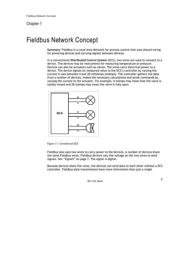
In a conventional Distributed Control System (DCS), two wires are used to connect to a
device. The devices may be instruments for measuring temperature or pressure.
Devices can also be actuators such as valves. The wires carry electrical power to a
device. The device signals its measured value to the DCS’s controller by varying the
current it uses between 4 and 20 milliAmps (mAmps). The controller gathers the data
from a number of devices, makes the necessary calculations and sends commands by
varying the current to the actuator. For example, 4 mAmps may mean that the valve is
totally closed and 20 mAmps may mean the valve is fully open.
Figure 1.1: Conventional DCS
Fieldbus also uses two wires to carry power to the devices. A number of devices share
the same Fieldbus wires. Fieldbus devices vary the voltage on the two wires to send
signals. See “Signals” on page 7. The signal is digital.
Because devices share the wires, the devices can send data to each other without a DCScontroller. Fieldbus data transmissions have more information than just a single
501-123, RevA3
7/27/2019 Guia Para Uso de Fieldbus
http://slidepdf.com/reader/full/guia-para-uso-de-fieldbus 9/53
Fieldbus Network Concept
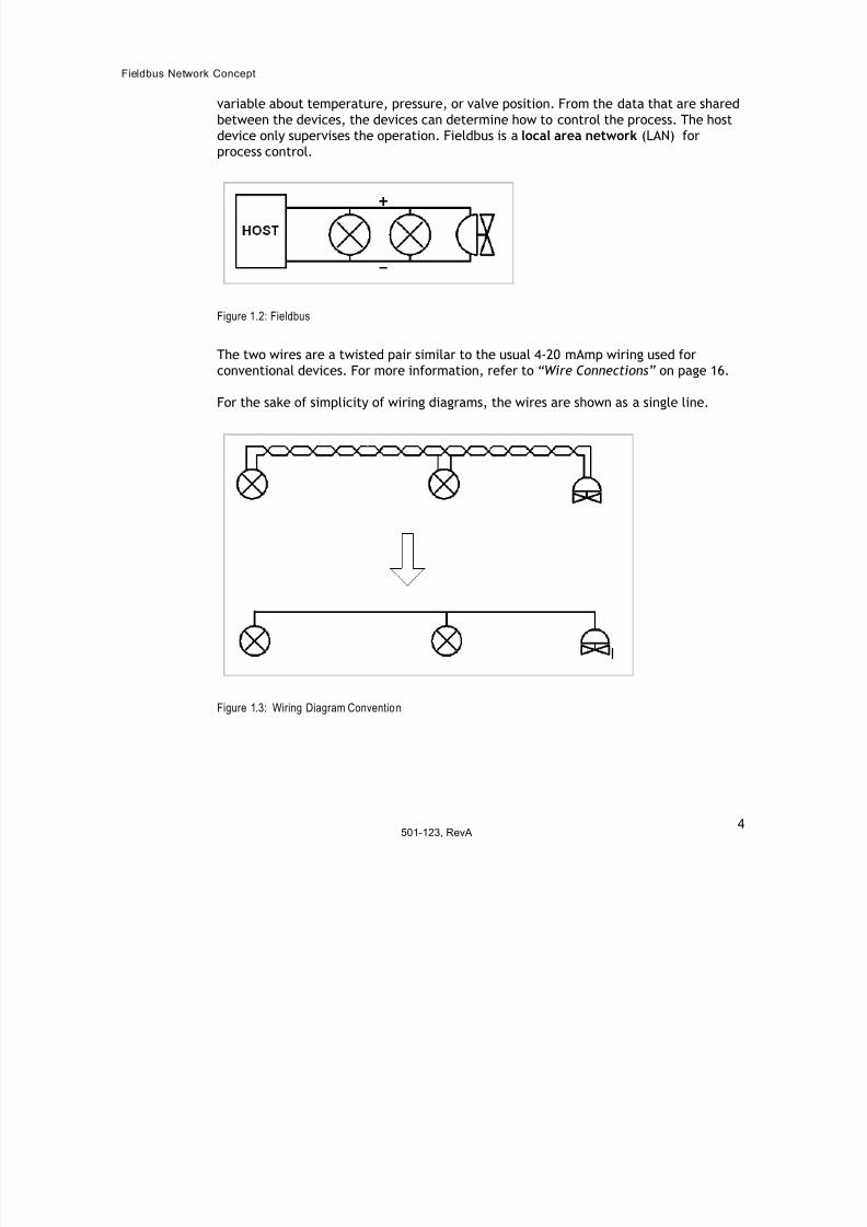
variable about temperature, pressure, or valve position. From the data that are shared
between the devices, the devices can determine how to control the process. The host
device only supervises the operation. Fieldbus is a local area network (LAN) for
process control.
Figure 1.2: Fieldbus
The two wires are a twisted pair similar to the usual 4-20 mAmp wiring used for
conventional devices. For more information, refer to “Wire Connections” on page 16.
For the sake of simplicity of wiring diagrams, the wires are shown as a single line.
Figure 1.3: Wiring Diagram Convention
501-123, RevA4
7/27/2019 Guia Para Uso de Fieldbus
http://slidepdf.com/reader/full/guia-para-uso-de-fieldbus 10/53
Fieldbus Configu ration
Chapter 2
Fieldbus Configuration
Summary: Fieldbus network’s shared wiring carries power to devices and signals
between devices. Two terminators are required. A power supply and a power
conditioner are needed to provide Fieldbus power.
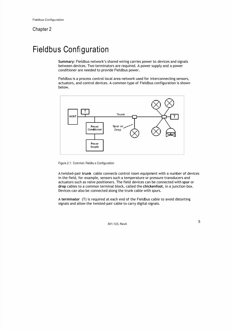
Fieldbus is a process control local area network used for interconnecting sensors,
actuators, and control devices. A common type of Fieldbus configuration is shown
below.
Figure 2.1: Common Fieldbus Configuration
A twisted-pair trunk cable connects control room equipment with a number of devices
in the field, for example, sensors such a temperature or pressure transducers and
actuators such as valve positioners. The field devices can be connected with spur or
drop cables to a common terminal block, called the chickenfoot, in a junction box.
Devices can also be connected along the trunk cable with spurs.
A terminator (T) is required at each end of the Fieldbus cable to avoid distorting
signals and allow the twisted-pair cable to carry digital signals.
501-123, RevA5
7/27/2019 Guia Para Uso de Fieldbus
http://slidepdf.com/reader/full/guia-para-uso-de-fieldbus 11/53
Fieldbus Configu ration
Power to the devices is provided by a power supply through a power conditioner (PC).
The power conditioner is needed to separate a conventional power supply from the
Fieldbus wiring so that the signals are not absorbed by the power supply.
A host or H1 device is usually located in the control room. Its function is to oversee the
operation of the control system made up of devices connected by the Fieldbus network.
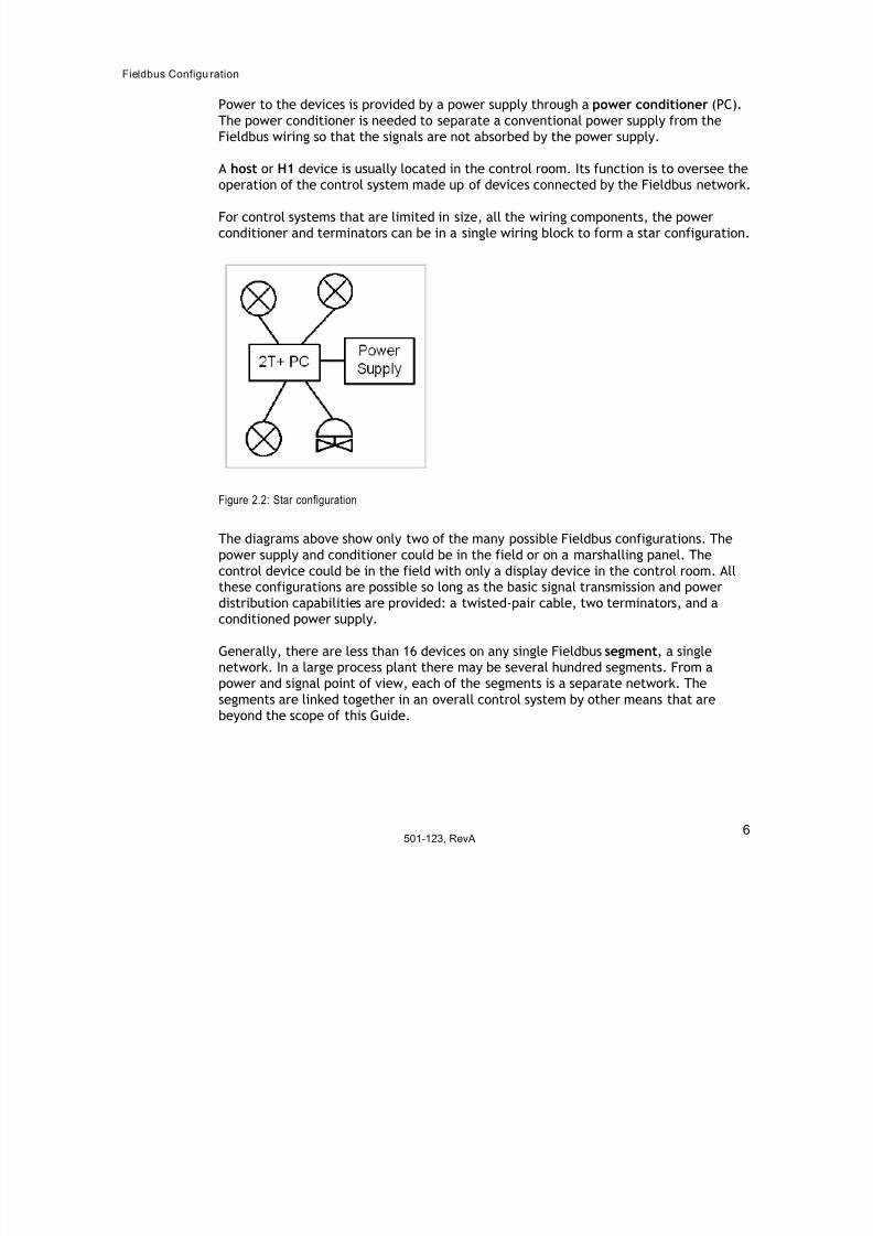
For control systems that are limited in size, all the wiring components, the power
conditioner and terminators can be in a single wiring block to form a star configuration.
Figure 2.2: Star configuration
The diagrams above show only two of the many possible Fieldbus configurations. The
power supply and conditioner could be in the field or on a marshalling panel. The
control device could be in the field with only a display device in the control room. All
these configurations are possible so long as the basic signal transmission and power
distribution capabilities are provided: a twisted-pair cable, two terminators, and a
conditioned power supply.
Generally, there are less than 16 devices on any single Fieldbus segment, a single
network. In a large process plant there may be several hundred segments. From a
power and signal point of view, each of the segments is a separate network. The
segments are linked together in an overall control system by other means that are
beyond the scope of this Guide.
501-123, RevA6

7/27/2019 Guia Para Uso de Fieldbus
http://slidepdf.com/reader/full/guia-para-uso-de-fieldbus 12/53
Signals
7501-123, RevA
Chapter 3
Signals
Summary: Devices signal each other by varying the current they draw from the network.
The signal is Manchester coded. The LAS arbitrates which device can use the network for
signaling.
The twisted pair cables, terminators, and the power conditioner work together as a
wiring system that can carry signals between Fieldbus devices. When a device is enabled
to signal (See “LAS” on page 10), it varies the amount of current it draws from the
network.
When not transmitting, a device draws power from the cable for its internal operation.
It also draws an additional 10 mAmps that it "wastes." When the device transmits a highsignal, it turns off this extra 10 mAmps. This increases the voltage between the wires.
When the device transmits a low signal, it draws an extra 10 mAmps from the wires,
resulting in a voltage decrease. The signal waveform is shown below. Note that the
signal is above and below the 24-volt non-transmitting level on the network.
Figure 3.1: Fieldbus signal
Digital data is sent on the Fieldbus at a rate of 31.25 kbits/second. Thus, each bit cell is32 microseconds long. The digital data, ones and zeros, is represented as a Manchester

7/27/2019 Guia Para Uso de Fieldbus
http://slidepdf.com/reader/full/guia-para-uso-de-fieldbus 13/53
Signals
8501-123, RevA
code. A zero is a positive signal transition in the middle of a bit cell; a one is a negative
transition in the middle of a bit cell. A sequence of Manchester encoded ones and zeros
would look like this:
Figure 3.2: Manchester code signal
When a device begins transmitting, it puts out a preamble, an 8-bit sequence with
alternating ones and zeros.
Figure 3.3: Preamble
This pattern is used by the receiving devices to synchronize themselves to bit cell
boundaries.
Besides ones and zeros, there are also two non-data symbols. These non-data symbols
are N+, a high level during the whole bit cell, and N-, a low level during the whole bit
cell. These symbols are used to make an 8-bit start delimiter that shows where real
data starts and an 8-bit end delimiter that shows where data transmission stops.

7/27/2019 Guia Para Uso de Fieldbus
http://slidepdf.com/reader/full/guia-para-uso-de-fieldbus 14/53
Signals
9501-123, RevA
Figure 3.4: Start and end delimiters
7/27/2019 Guia Para Uso de Fieldbus
http://slidepdf.com/reader/full/guia-para-uso-de-fieldbus 15/53
Signals
10501-123, RevA
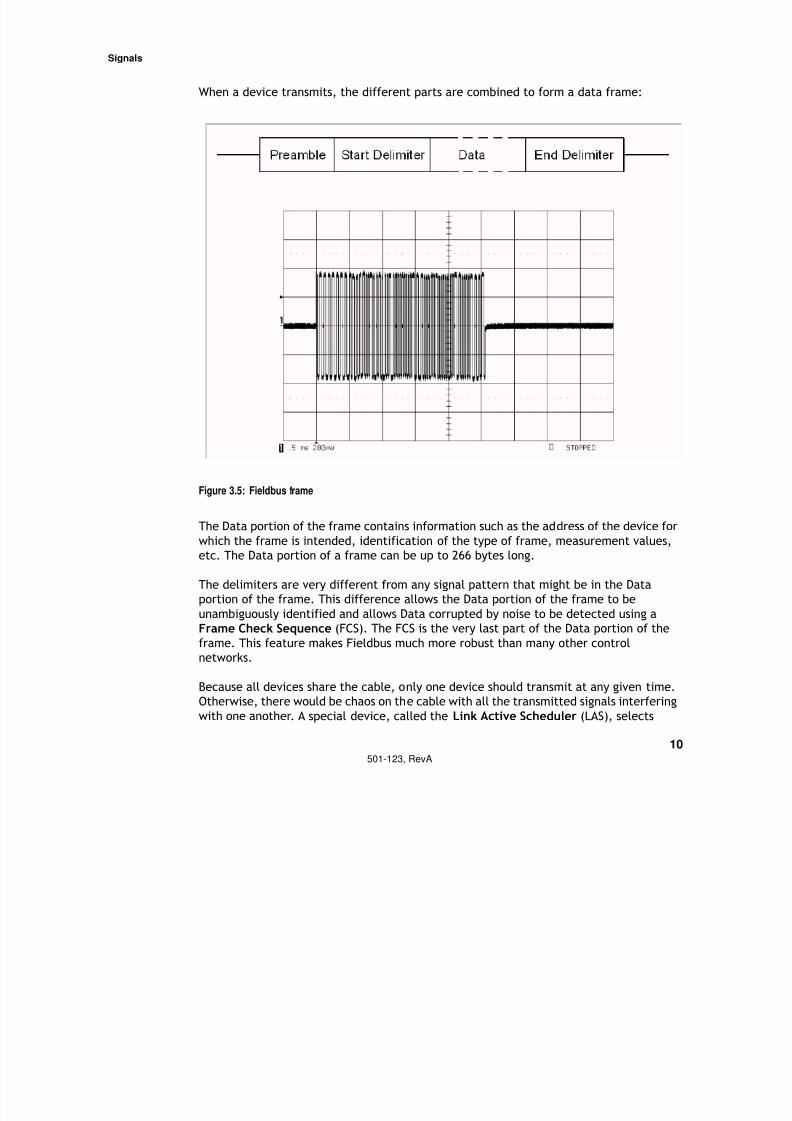
When a device transmits, the different parts are combined to form a data frame:
Figure 3.5: Fieldbus frame
The Data portion of the frame contains information such as the address of the device for
which the frame is intended, identification of the type of frame, measurement values,
etc. The Data portion of a frame can be up to 266 bytes long.
The delimiters are very different from any signal pattern that might be in the Data
portion of the frame. This difference allows the Data portion of the frame to be
unambiguously identified and allows Data corrupted by noise to be detected using a
Frame Check Sequence (FCS). The FCS is the very last part of the Data portion of the
frame. This feature makes Fieldbus much more robust than many other control
networks.
Because all devices share the cable, only one device should transmit at any given time.
Otherwise, there would be chaos on the cable with all the transmitted signals interfering
with one another. A special device, called the Link Active Scheduler (LAS), selects

7/27/2019 Guia Para Uso de Fieldbus
http://slidepdf.com/reader/full/guia-para-uso-de-fieldbus 16/53
Signals
11501-123, RevA
which single device can transmit. The LAS allows each device to transmit by sending out
a special frame to each device in turn. A frame might be: the LAS asking a device to
transmit data, a device broadcasting its data to other devices, a device reporting anerror condition, etc. If an oscilloscope were used to observe the signals on the Fieldbus,
the display would show frames with gaps of silence between them, as shown below:
Figure 3.6: Multiple Fieldbus frames
How Fieldbus is used for conveying specific types of process information is beyond the
scope of this Guide.
7/27/2019 Guia Para Uso de Fieldbus
http://slidepdf.com/reader/full/guia-para-uso-de-fieldbus 17/53
Fieldbus Cable
12
501-123, RevA
Chapter 4
Fieldbus Cable
Summary: Fieldbus uses shielded, twisted-pair cable. The shield is grounded at only one
place.
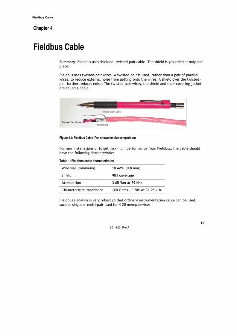
Fieldbus uses twisted-pair wires. A twisted-pair is used, rather than a pair of parallel
wires, to reduce external noise from getting onto the wires. A shield over the twisted-
pair further reduces noise. The twisted-pair wires, the shield and their covering jacket
are called a cable.
Figure 4.1: Fieldbus Cable (Pen shown for size comparison)
For new installations or to get maximum performance from Fieldbus, the cable should
have the following characteristics
Fieldbus signaling is very robust so that ordinary instrumentation cable can be used,
such as single or multi-pair used for 4–20 mAmp devices.
Table 1: Fieldbus cable characteristics
Wire size (minimum) 18 AWG (0.8 mm)
Shield 90% coverage
Attenuation 3 dB/km at 39 kHz
Characteristic Impedance 100 Ohms +/-20% at 31.25 kHz

7/27/2019 Guia Para Uso de Fieldbus
http://slidepdf.com/reader/full/guia-para-uso-de-fieldbus 18/53
Fieldbus Cable
13
501-123, RevA
If possible, to avoid confusion, the wire insulation colors should match the color
convention of existing wiring in the plant. If new cable is installed, the suggested
convention is orange for the (+) wire and blue for the (-).
The shield is continuous throughout the network. The shield is connected to ground at
only one place, usually at the power supply. The shield is not connected to ground at the
devices or any other place.
There may be regulatory requirements for cable jacketing, such as armor, depending
where the cable is used.
7/27/2019 Guia Para Uso de Fieldbus
http://slidepdf.com/reader/full/guia-para-uso-de-fieldbus 19/53
Terminator
14
501-123, RevA
Chapter 5
Terminator
Summary: A terminator is needed at each end of the Fieldbus network segment.
Two terminators are required on each Fieldbus network segment. Generally, oneterminator is at the control room end of the cable and the other terminator is in the
junction box in the field.
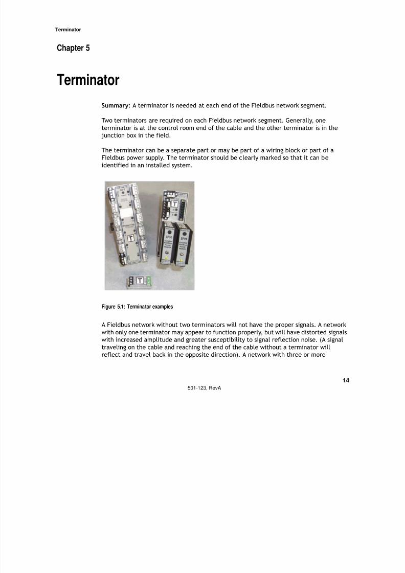
The terminator can be a separate part or may be part of a wiring block or part of a
Fieldbus power supply. The terminator should be clearly marked so that it can be
identified in an installed system.
Figure 5.1: Terminator examples
A Fieldbus network without two terminators will not have the proper signals. A network
with only one terminator may appear to function properly, but will have distorted signals
with increased amplitude and greater susceptibility to signal reflection noise. (A signal
traveling on the cable and reaching the end of the cable without a terminator will
reflect and travel back in the opposite direction). A network with three or more

7/27/2019 Guia Para Uso de Fieldbus
http://slidepdf.com/reader/full/guia-para-uso-de-fieldbus 20/53
Terminator
15
501-123, RevA
terminators will have decreased signal amplitude to the point where devices may lose
the ability to communicate with one another.
7/27/2019 Guia Para Uso de Fieldbus
http://slidepdf.com/reader/full/guia-para-uso-de-fieldbus 21/53
Wire Connections
16
501-123, RevA
Chapter 6
Wire Connections
Summary: Fieldbus wiring blocks make wiring easier, more reliable, and provide
additional features.
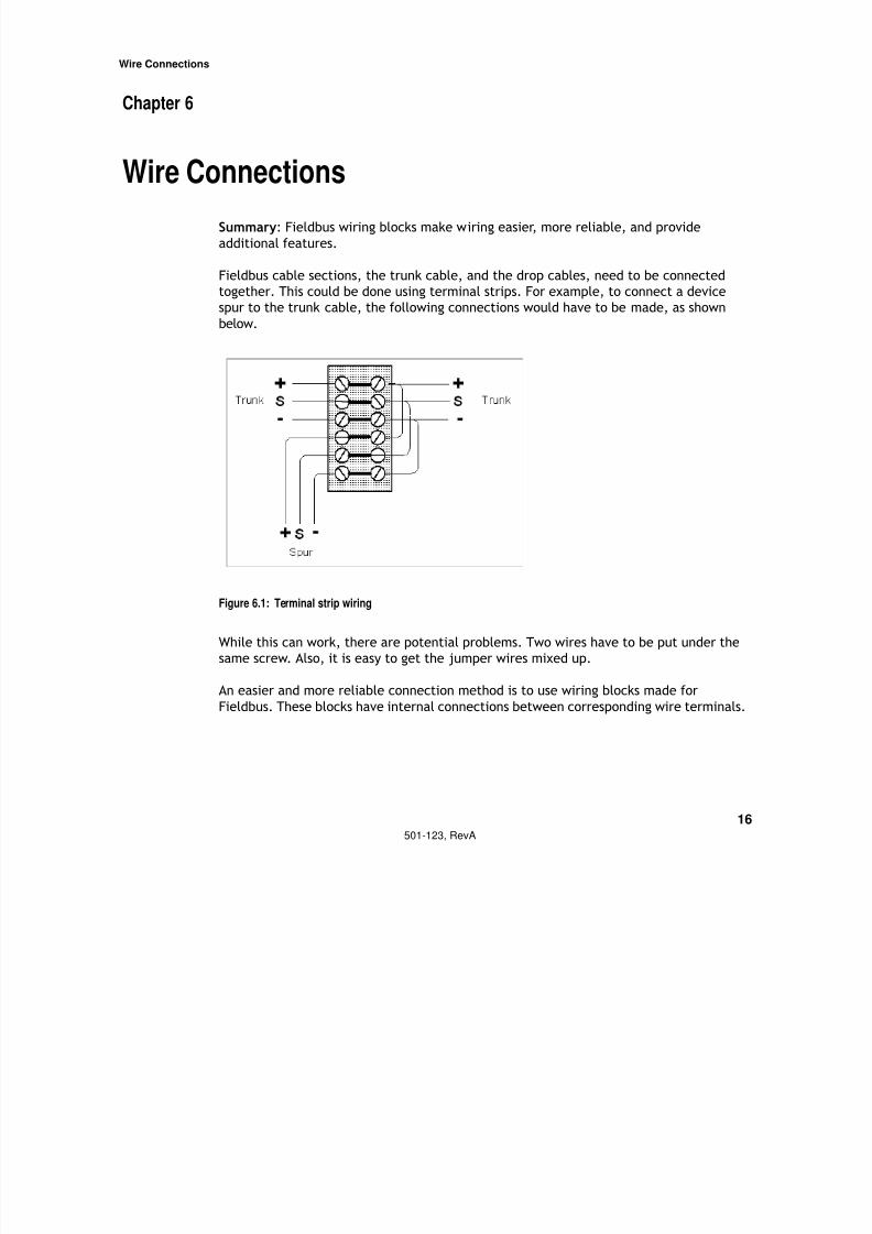
Fieldbus cable sections, the trunk cable, and the drop cables, need to be connected
together. This could be done using terminal strips. For example, to connect a device
spur to the trunk cable, the following connections would have to be made, as shown
below.
Figure 6.1: Terminal strip wiring
While this can work, there are potential problems. Two wires have to be put under thesame screw. Also, it is easy to get the jumper wires mixed up.
An easier and more reliable connection method is to use wiring blocks made for
Fieldbus. These blocks have internal connections between corresponding wire terminals.
7/27/2019 Guia Para Uso de Fieldbus
http://slidepdf.com/reader/full/guia-para-uso-de-fieldbus 22/53
Wire Connections
17
501-123, RevA
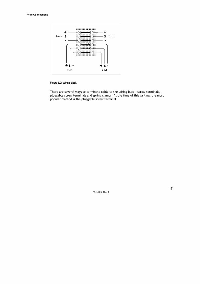
Figure 6.2: Wiring block
There are several ways to terminate cable to the wiring block: screw terminals,
pluggable screw terminals and spring clamps. At the time of this writing, the most
popular method is the pluggable screw terminal.

7/27/2019 Guia Para Uso de Fieldbus
http://slidepdf.com/reader/full/guia-para-uso-de-fieldbus 23/53
Wire Connections
18
501-123, RevA
Figure 6.3: Wiring block examples (a and b)
Figure 6.3a shows a photograph of two wiring blocks and a terminator in a junction box.
The black connectors are for the trunk cable.
Figure 6.3b shows this arrangement schematically. The trunk cable is attached to theupper left-hand terminal of the 8-drop wiring block. The other end of the 8-way wiring
block is connected to the 4-way wiring block with a short jumper cable. The other end of
the 4-way wiring block is connected to the terminator, (T).
This example shows how 12 Fieldbus devices are interconnected in a junction box. If the
two wiring blocks had been in two separate junction boxes, the jumper cable would
simply be a longer cable between the junction boxes.
7/27/2019 Guia Para Uso de Fieldbus
http://slidepdf.com/reader/full/guia-para-uso-de-fieldbus 24/53
Wire Connections
19
501-123, RevA
Using pluggable screw terminals, the cable can be prepared and attached to the plug
without reaching into the often tight spaces of a junction box. The plug is then inserted
into the wiring block and fastened so that it does not vibrate out or becomedisconnected if cables are moved.
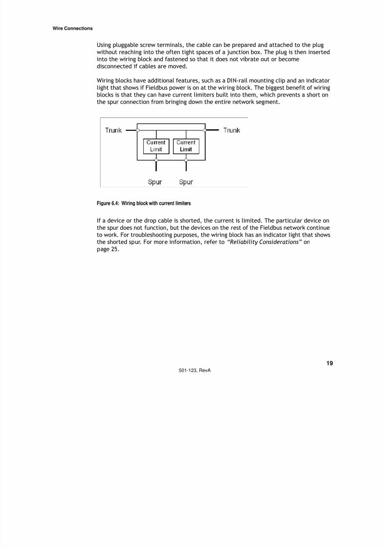
Wiring blocks have additional features, such as a DIN-rail mounting clip and an indicator
light that shows if Fieldbus power is on at the wiring block. The biggest benefit of wiring
blocks is that they can have current limiters built into them, which prevents a short on
the spur connection from bringing down the entire network segment.
Figure 6.4: Wiring block with current limiters
If a device or the drop cable is shorted, the current is limited. The particular device on
the spur does not function, but the devices on the rest of the Fieldbus network continueto work. For troubleshooting purposes, the wiring block has an indicator light that shows
the shorted spur. For more information, refer to “Reliability Considerations” on
page 25.
7/27/2019 Guia Para Uso de Fieldbus
http://slidepdf.com/reader/full/guia-para-uso-de-fieldbus 25/53
Fieldbus Power
Voltage 20501-123, RevA
Chapter 7
Fieldbus Power
Summary: A power conditioner is needed between a power supply and the Fieldbus
wires to power a Fieldbus.
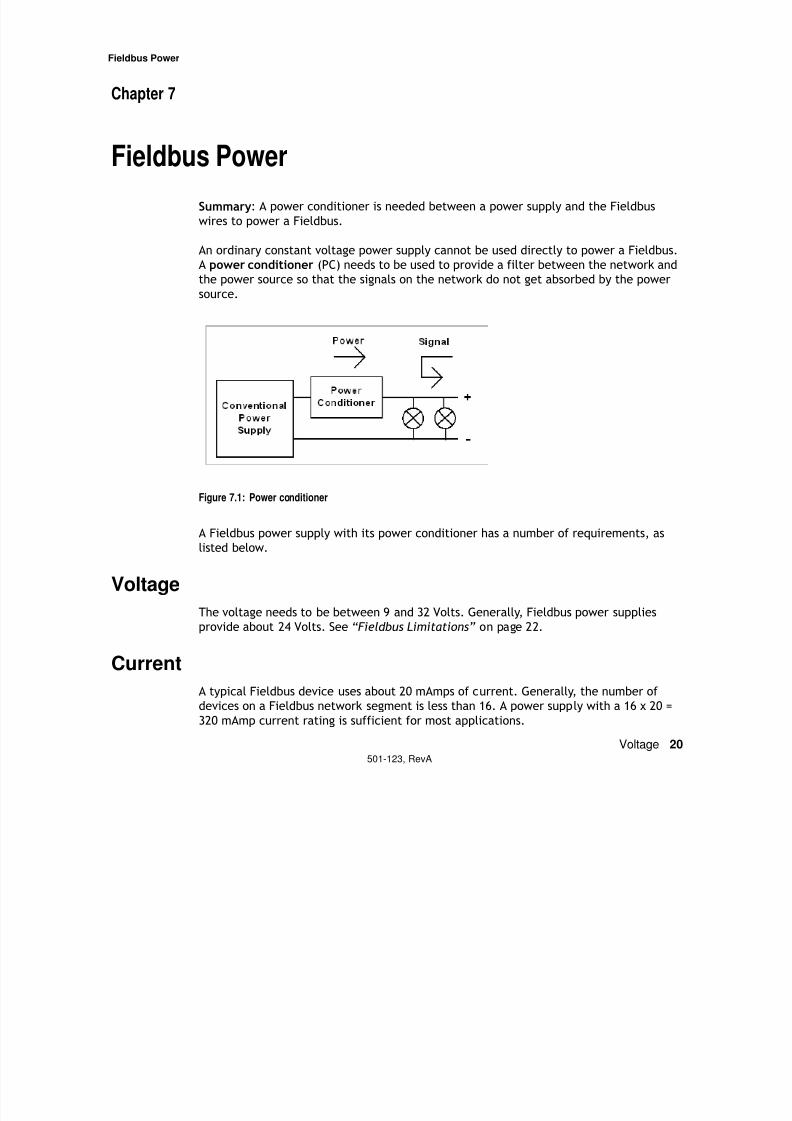
An ordinary constant voltage power supply cannot be used directly to power a Fieldbus.
A power conditioner (PC) needs to be used to provide a filter between the network and
the power source so that the signals on the network do not get absorbed by the power
source.
Figure 7.1: Power conditioner
A Fieldbus power supply with its power conditioner has a number of requirements, as
listed below.
VoltageThe voltage needs to be between 9 and 32 Volts. Generally, Fieldbus power supplies
provide about 24 Volts. See “Fieldbus Limitations” on page 22.
Current
A typical Fieldbus device uses about 20 mAmps of current. Generally, the number of devices on a Fieldbus network segment is less than 16. A power supply with a 16 x 20 =
320 mAmp current rating is sufficient for most applications.
7/27/2019 Guia Para Uso de Fieldbus
http://slidepdf.com/reader/full/guia-para-uso-de-fieldbus 26/53
Fieldbus Power
Galvanic Isolation 21501-123, RevA
Galvanic Isolation
The power supply and power conditioner combination needs to be electrically isolatedfrom grounds. This means that bulk 24 V DC power supplies that have one output
grounded cannot be used with power conditioners if they do not themselves provide
electrical isolation. Galvanic isolation is important in minimizing noise ingress and
providing network reliability.
There are a number of other power supply requirements such as noise, short circuit
recovery, segment crosstalk, etc. These requirements will be defined in the upcoming
Foundation Fieldbus power supply test specification FF-641.
Fieldbus network operation is totally dependent on the power supply. If the power
supply or the power conditioner fails, power to the entire network segment and the
process it controls is lost. For control systems that require high availability, redundant
Fieldbus power supplies are used. For more information, refer to “Power supply failure”
on page 27.
If Fieldbus is used in hazardous areas, additional requirements are placed on the powersupplies.

7/27/2019 Guia Para Uso de Fieldbus
http://slidepdf.com/reader/full/guia-para-uso-de-fieldbus 27/53
Fieldbus Limitations
Power Distribution 22501-123, RevA
Chapter 8
Fieldbus Limitations
Summary: Power distribution, attenuation, and signal distortion limit the size of a
Fieldbus network segment and the number of devices that can be interconnected.
Power Distribution
The number of devices that can be on a Fieldbus segment is limited by the power supply
voltage, the resistance of the cable, and the amount of current drawn by the devices.
The following example shows how to calculate the maximum number of devices that can
be attached at the chickenfoot.
• The Fieldbus power supply output is 20 Volts to the network.
• The cable used is 18 gauge and has a resistance of 22 Ohms/km for each conduc-
tor. The trunk cable is 1 km long. The combined resistance of both wires is 44
Ohms.
• Each device at the chickenfoot draws 20 mAmps.
Since the minimum voltage needed by a device is 9 Volts, there are 20 - 9 = 11 Volts that
are available to be used by the cable resistance. The total current that can be suppliedat the chickenfoot is:
Voltage / Resistance = Current available
11 Volts / 44 Ohms/km = 250 mAmps
Since each device draws 20 mAmps, the maximum number of devices at the chickenfoot
of this example is:
Current available / Device draw = Number of devices
250 mAmps / 20 mAmps = 12 devices
When devices are attached to the cable at different places, the power distribution
calculation becomes more involved. Generally, the cable length is much shorter than 1
km and the Fieldbus power supply voltage is higher so that power distribution is not a bigissue.
7/27/2019 Guia Para Uso de Fieldbus
http://slidepdf.com/reader/full/guia-para-uso-de-fieldbus 28/53
Fieldbus Limitations
Attenuation 23501-123, RevA
Attenuation
As signals travel on a Fieldbus cable, they are attenuated, that is, they are reduced inamplitude. The longer the cable, the greater the attenuation. The Fieldbus standard
requires that a Fieldbus device transmits a signal at least 0.75 Volts peak-to-peak and
that a receiver must be able to detect a signal of as little as 0.15 Volts peak-to-peak. (In
electrical engineering talk, this is 14 dB of attenuation). If standard Fieldbus cable is
used (attenuation of 3 dB/ km), then the cable can be
14 dB / 3 dB/km = 4.6 km long.
However, there is additional attenuation that needs to be considered. Signals are also
attenuated by the spur cables that branch off the trunk cable. This attenuation is largely
caused by cable capacitance. Standard Fieldbus cable capacitance is about 0.15 nF/
meter and the attenuation caused by capacitance is about 0.035 dB/nF. As an example,
if the lengths of all the spurs is 500 meters, then the attenuation will be
500 meters x 0.15 nF/meter x 0.035 dB/nF = 2.6 dB.
As an example, assume that the trunk cable is 800 meters long. The trunk attenuation is
3 dB/ km x 0.8 km = 2.4 dB.
The total signal attenuation is
2.6 dB + 2.4 dB = 5 dB.
This is well within the 14 dB available.
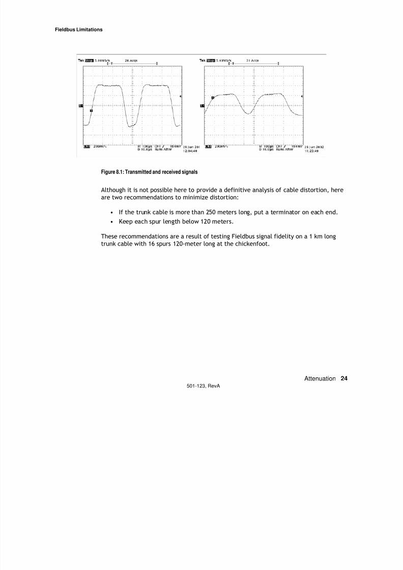
Signal Distortion
Fieldbus cable is limited to less than the theoretically possible length. Signals also get
distorted by various cable characteristics, spur reflections, etc. Shown below on the left
is a transmitted signal and on the right a received signal at the end of a 900 meter long
cable with 16 120-meter spurs at the chickenfoot.
7/27/2019 Guia Para Uso de Fieldbus
http://slidepdf.com/reader/full/guia-para-uso-de-fieldbus 29/53
Fieldbus Limitations
Attenuation 24501-123, RevA
Figure 8.1: Transmitted and received signals
Although it is not possible here to provide a definitive analysis of cable distortion, here
are two recommendations to minimize distortion:
• If the trunk cable is more than 250 meters long, put a terminator on each end.
• Keep each spur length below 120 meters.
These recommendations are a result of testing Fieldbus signal fidelity on a 1 km longtrunk cable with 16 spurs 120-meter long at the chickenfoot.
R li bilit C id ti
7/27/2019 Guia Para Uso de Fieldbus
http://slidepdf.com/reader/full/guia-para-uso-de-fieldbus 30/53
Reliability Considerations
25501-123, RevA
Chapter 9
Reliability Considerations
Summary: Since Fieldbus uses shared wiring, reliability precautions need to be taken for
networks used in critical applications. Reliability enhancement includes short circuit
protectors on spur cables, protected trunk cable, redundant power supplies andlightning surge protectors.
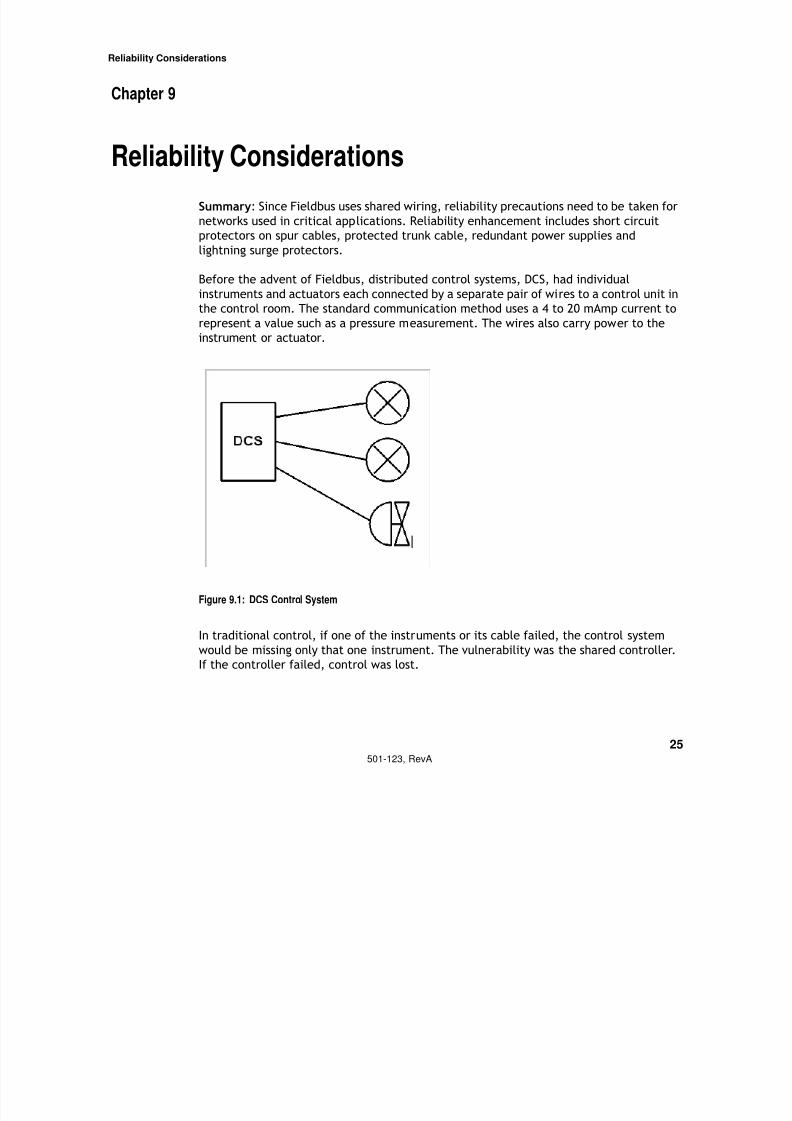
Before the advent of Fieldbus, distributed control systems, DCS, had individual
instruments and actuators each connected by a separate pair of wires to a control unit in
the control room. The standard communication method uses a 4 to 20 mAmp current to
represent a value such as a pressure measurement. The wires also carry power to the
instrument or actuator.
Figure 9.1: DCS Control System
In traditional control, if one of the instruments or its cable failed, the control system
would be missing only that one instrument. The vulnerability was the shared controller.
If the controller failed, control was lost.
Reliability Considerations
7/27/2019 Guia Para Uso de Fieldbus
http://slidepdf.com/reader/full/guia-para-uso-de-fieldbus 31/53
Reliability Considerations
Spur shorts 26501-123, RevA
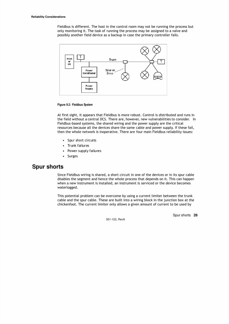
Fieldbus is different. The host in the control room may not be running the process but
only monitoring it. The task of running the process may be assigned to a valve and
possibly another field device as a backup in case the primary controller fails.
Figure 9.2: Fieldbus System
At first sight, it appears that Fieldbus is more robust. Control is distributed and runs in
the field without a central DCS. There are, however, new vulnerabilities to consider. In
Fieldbus-based systems, the shared wiring and the power supply are the critical
resources because all the devices share the same cable and power supply. If these fail,
then the whole network is inoperative. There are four main Fieldbus reliability issues:
• Spur short circuits
• Trunk failures
• Power supply failures
• Surges
Spur shortsSince Fieldbus wiring is shared, a short circuit in one of the devices or in its spur cable
disables the segment and hence the whole process that depends on it. This can happen
when a new instrument is installed, an instrument is serviced or the device becomes
waterlogged.
This potential problem can be overcome by using a current limiter between the trunk
cable and the spur cable. These are built into a wiring block in the junction box at the
chickenfoot. The current limiter only allows a given amount of current to be used by
Reliability Considerations
7/27/2019 Guia Para Uso de Fieldbus
http://slidepdf.com/reader/full/guia-para-uso-de-fieldbus 32/53
Reliability Considerations
Trunk cable failures 27501-123, RevA
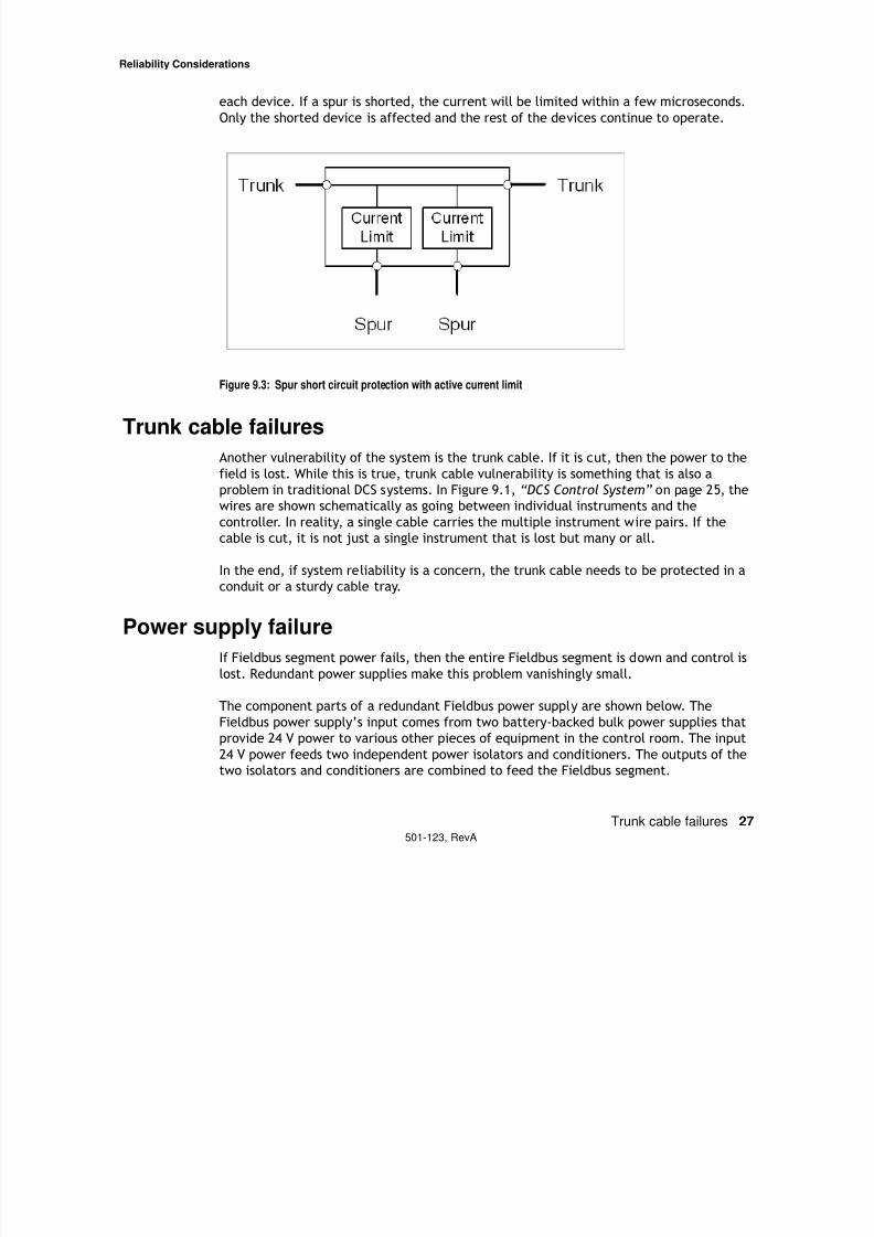
each device. If a spur is shorted, the current will be limited within a few microseconds.
Only the shorted device is affected and the rest of the devices continue to operate.
Figure 9.3: Spur short circuit protection with active current limit
Trunk cable failures
Another vulnerability of the system is the trunk cable. If it is cut, then the power to the
field is lost. While this is true, trunk cable vulnerability is something that is also a
problem in traditional DCS systems. In Figure 9.1, “DCS Control System” on page 25, the
wires are shown schematically as going between individual instruments and the
controller. In reality, a single cable carries the multiple instrument wire pairs. If thecable is cut, it is not just a single instrument that is lost but many or all.
In the end, if system reliability is a concern, the trunk cable needs to be protected in a
conduit or a sturdy cable tray.
Power supply failure
If Fieldbus segment power fails, then the entire Fieldbus segment is down and control is
lost. Redundant power supplies make this problem vanishingly small.
The component parts of a redundant Fieldbus power supply are shown below. The
Fieldbus power supply’s input comes from two battery-backed bulk power supplies that
provide 24 V power to various other pieces of equipment in the control room. The input
24 V power feeds two independent power isolators and conditioners. The outputs of the
two isolators and conditioners are combined to feed the Fieldbus segment.
Reliability Considerations
7/27/2019 Guia Para Uso de Fieldbus
http://slidepdf.com/reader/full/guia-para-uso-de-fieldbus 33/53
y
Power supply failure 28501-123, RevA
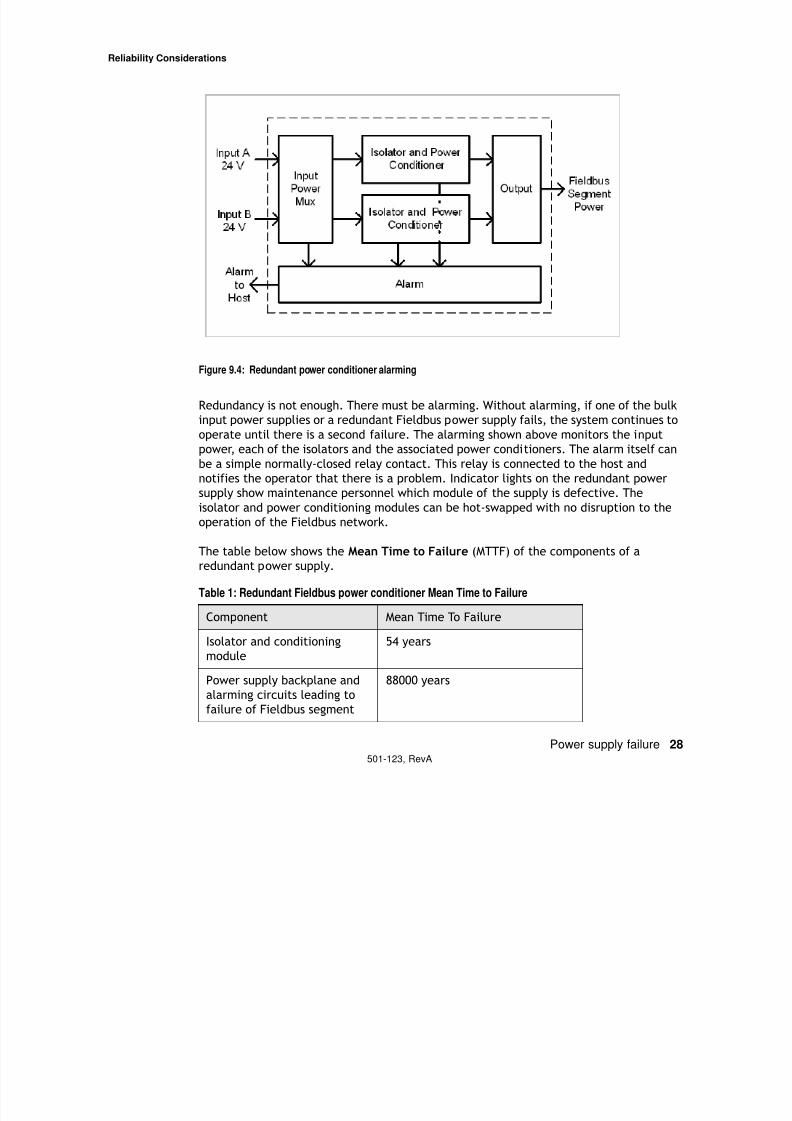
Figure 9.4: Redundant power conditioner alarming
Redundancy is not enough. There must be alarming. Without alarming, if one of the bulk
input power supplies or a redundant Fieldbus power supply fails, the system continues to
operate until there is a second failure. The alarming shown above monitors the input
power, each of the isolators and the associated power conditioners. The alarm itself can
be a simple normally-closed relay contact. This relay is connected to the host andnotifies the operator that there is a problem. Indicator lights on the redundant power
supply show maintenance personnel which module of the supply is defective. The
isolator and power conditioning modules can be hot-swapped with no disruption to the
operation of the Fieldbus network.
The table below shows the Mean Time to Failure (MTTF) of the components of a
redundant power supply.
Table 1: Redundant Fieldbus power conditioner Mean Time to Failure
Component Mean Time To Failure
Isolator and conditioning
module
54 years
Power supply backplane and
alarming circuits leading tofailure of Fieldbus segment
88000 years
Reliability Considerations
7/27/2019 Guia Para Uso de Fieldbus
http://slidepdf.com/reader/full/guia-para-uso-de-fieldbus 34/53
Lightning Surges 29501-123, RevA
A more useful figure for the control engineer is the Availability of a system. To calculate
availability, we also need to know the Mean Time To Repair. The MTTR for a failure which
raises an alarm is typically taken as 8 hours (1 shift) to cover the time taken to recognizethe alarm, get the necessary authorizations to work on the system, collect a spare from
stores and complete the replacement.
The Availability is
To calculate the availability of the Fieldbus segment due to the power supply, we needto consider
• The MTTF of the isolator and power conditioning modules and
• The MTTF of the common components on the backplane whose failure would
result in the failure of the Fieldbus segment.
With two power supply modules operating, the Unavailability, (1 – Availability), of the
redundant power supply is the probability of both modules being unavailable at thesame time. This is calculated as the product of the individual power module
unavailabilities.
The unavailability for the Fieldbus segment is based on
• Both the isolation and power conditioning modules failing at the same time or
• The common backplane components failing which affect segment availability
The unavailability of the Fieldbus segment is the sum of these two unavailabilities.
From this, the Availability for a Fieldbus segment with the redundant isolator and power
conditioner system is 99.9999989%. This means that a Fieldbus system could be down
due to redundant power supply failures on average for 0.3 seconds/year.
Lightning SurgesThere is no protection against a direct lightning strike. The energy involved is too great.
The struck device simply disintegrates.
Lightning strikes also have effects at great distances from the strike point. The voltage
between earth points that are normally considered at the same potential become large.
If a cable connects devices that are at some distance from each other, the ground
potential difference can travel over the cable and break down the electrical isolation of
Reliability Considerations

7/27/2019 Guia Para Uso de Fieldbus
http://slidepdf.com/reader/full/guia-para-uso-de-fieldbus 35/53
Lightning Surges 30501-123, RevA
Fieldbus devices. Since many Fieldbus devices share the same cable, a lightning surge
can adversely affect all of them.
The general rule is that if the a horizontal distance between devices of greater than
100m or vertical separation greater than 10m, lightning surge protection should be used.
Given that Fieldbus devices are unlikely to all be mounted within a few meters of each
other, the voltage developed between any two devices could be large enough to
breakdown insulation and produce damage.
Isolation and Segment Independence
7/27/2019 Guia Para Uso de Fieldbus
http://slidepdf.com/reader/full/guia-para-uso-de-fieldbus 36/53
Galvanic Isolation 31501-123, RevA
Chapter 10
Isolation and Segment Independence
Summary: A Fieldbus segment must be electrically (galvanically) isolated from ground
and ideally should be galvanically isolated from other segments to make the network
more reliable. A good Fieldbus power supply satisfies these requirements.
There are a number of ways to power a Fieldbus segment. Some ways work better than
others. Consider the following information.
Galvanic Isolation
The Fieldbus standard requires that the power provided to a segment be galvanically
isolated from ground. Galvanic isolation provides maximum noise immunity. If you speakelectrical engineering, here is the reason for this requirement:
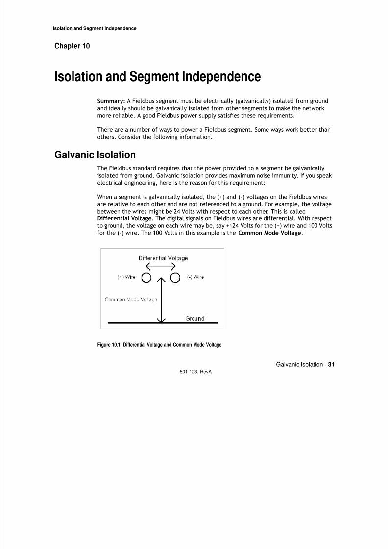
When a segment is galvanically isolated, the (+) and (-) voltages on the Fieldbus wires
are relative to each other and are not referenced to a ground. For example, the voltage
between the wires might be 24 Volts with respect to each other. This is called
Differential Voltage. The digital signals on Fieldbus wires are differential. With respect
to ground, the voltage on each wire may be, say +124 Volts for the (+) wire and 100 Volts
for the (-) wire. The 100 Volts in this example is the Common Mode Voltage.
Figure 10.1: Differential Voltage and Common Mode Voltage
Isolation and Segment Independence
7/27/2019 Guia Para Uso de Fieldbus
http://slidepdf.com/reader/full/guia-para-uso-de-fieldbus 37/53
Current Limiter Bypass 32501-123, RevA
The devices attached to the Fieldbus wires only “see” differential voltage. The reason
twisted pair wires are used for Fieldbus is that if noise gets on one wire, it also gets
equally on the other wire. Thus, noise is a common mode voltage. With galvanicisolation, there is no ground reference for the two Fieldbus signal wires to the grounded
shield so that conversion of common mode noise to differential noise is minimized. If
one of the Fieldbus wires were referenced to ground, the common mode noise on the
wires would not be equal and differential noise would be created. (The cable shield’s
function is to further reduce noise by keeping common mode noise off the two wires).
Current Limiter BypassGalvanic isolation from ground also provides another benefit. Current limiters are used
between the network’s trunk and the drop cable to a Fieldbus device to prevent a short
circuit on one spur from disabling the entire network segment. If a segment does not
have galvanic isolation, current limiter protection can be defeated.
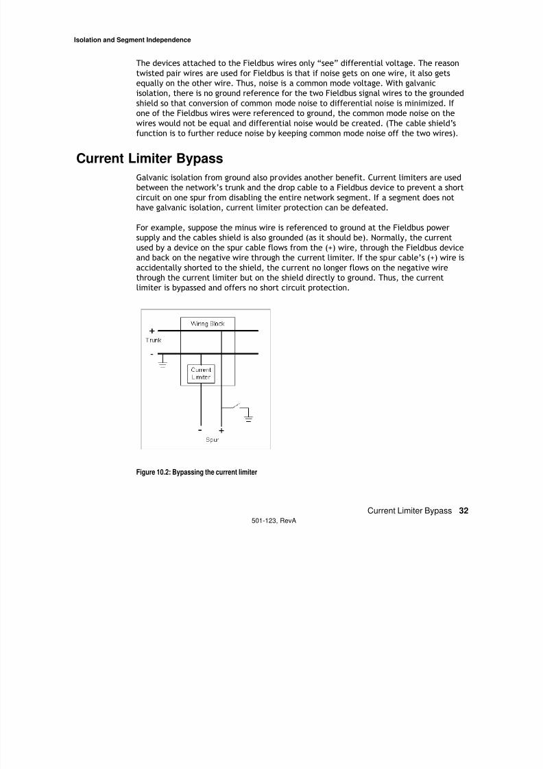
For example, suppose the minus wire is referenced to ground at the Fieldbus power
supply and the cables shield is also grounded (as it should be). Normally, the current
used by a device on the spur cable flows from the (+) wire, through the Fieldbus device
and back on the negative wire through the current limiter. If the spur cable’s (+) wire is
accidentally shorted to the shield, the current no longer flows on the negative wire
through the current limiter but on the shield directly to ground. Thus, the current
limiter is bypassed and offers no short circuit protection.
Figure 10.2: Bypassing the current limiter
Isolation and Segment Independence
7/27/2019 Guia Para Uso de Fieldbus
http://slidepdf.com/reader/full/guia-para-uso-de-fieldbus 38/53
Crosstalk 33501-123, RevA
A shield short to one of the network wires is a relatively common occurrence. When this
happens on a network powered by a galvanically isolated Fieldbus power supply, the
network still functions but with reduced noise immunity. Without galvanic isolationthere is a possibility that current limiters will not work.
Crosstalk
Fieldbus network segments should be independent from each other. A power conditioner
must have equal impedance on both wires of the segment or the segment must be
galvanically isolated from all other segments. Without this, there is crosstalk between
the two segments. “Crosstalk” means that signals on one segment partially appear onanother segment. Crosstalk is caused by capacitive coupling between segment wires and
the shield. This is a form of noise and makes network operation unreliable.
Multiple Wiring Errors
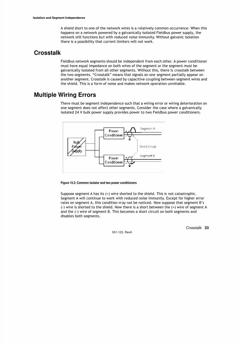
There must be segment independence such that a wiring error or wiring deterioration on
one segment does not affect other segments. Consider the case where a galvanicallyisolated 24 V bulk power supply provides power to two Fieldbus power conditioners.
Figure 10.3: Common isolator and two power conditioners
Suppose segment A has its (+) wire shorted to the shield. This is not catastrophic.
Segment A will continue to work with reduced noise immunity. Except for higher error
rates on segment A, this condition may not be noticed. Now suppose that segment B’s
(-) wire is shorted to the shield. Now there is a short between the (+) wire of segment A
and the (-) wire of segment B. This becomes a short circuit on both segments and
disables both segments.
Isolation and Segment Independence
7/27/2019 Guia Para Uso de Fieldbus
http://slidepdf.com/reader/full/guia-para-uso-de-fieldbus 39/53
Multiple Wiring Errors 34501-123, RevA
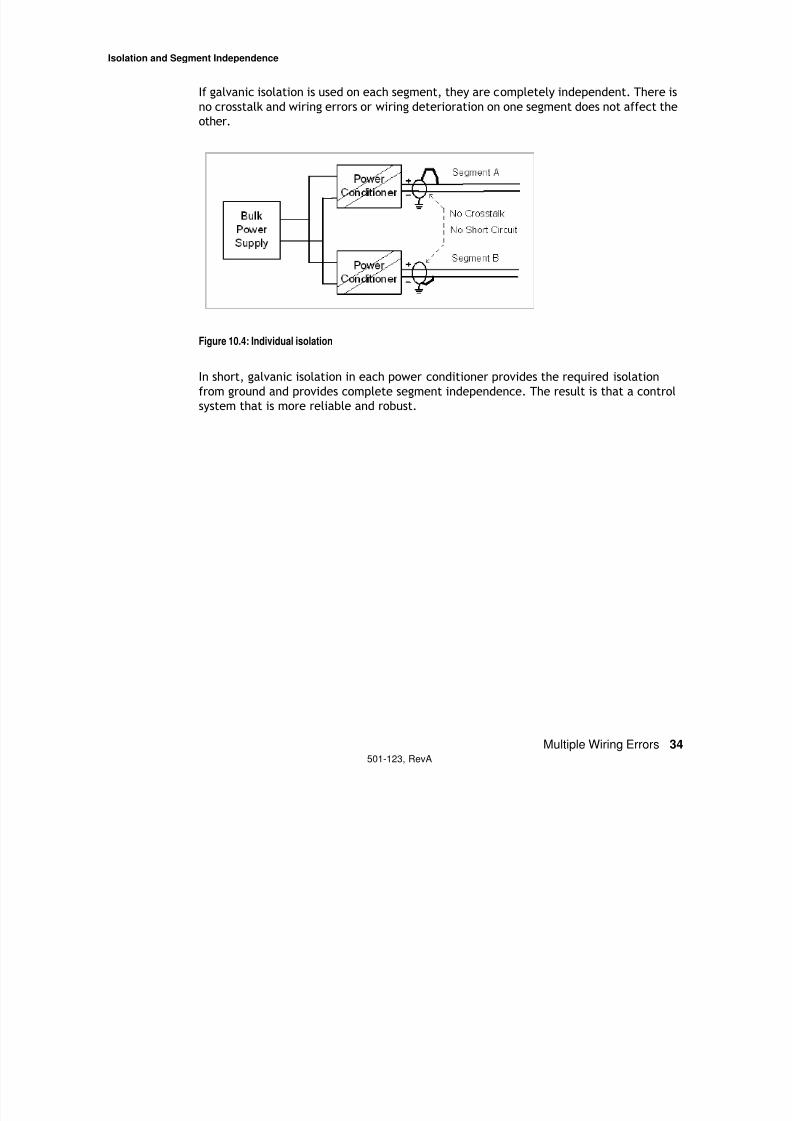
If galvanic isolation is used on each segment, they are completely independent. There is
no crosstalk and wiring errors or wiring deterioration on one segment does not affect the
other.
Figure 10.4: Individual isolation
In short, galvanic isolation in each power conditioner provides the required isolation
from ground and provides complete segment independence. The result is that a control
system that is more reliable and robust.
Fieldbus Cable Selection and Installation for Process Plants
7/27/2019 Guia Para Uso de Fieldbus
http://slidepdf.com/reader/full/guia-para-uso-de-fieldbus 40/53
Cable Types 35501-123, RevA
Chapter 11
Fieldbus Cable Selection and Installation for
Process Plants
By Ian Verhappen
The wires inside a Fieldbus cable are the same regardless of cable jacketing type: two
wires which are twisted with an overall shield covering them. The type of cable
jacketing selected and how the cable is installed depends on a number of factors. A
number of considerations relative to selection and installation of cables are summarized
below.
Note: Always refer to the local electrical codes and regulations prior to installing any
cable. This document is intended to provide a number of items that should be
considered when selecting cable for Fieldbus installations but in no way replaces the
requirement to have an electrical engineer or designer complete the final
documentation used for construction.
Cable Types
As indicated above, the actual conductors in the cable must still adhere to the
requirements of IEC61508 Part 1, in which the physical layer characteristics of the
various types of Fieldbus cable are defined. All cables should have a minimum twist as
specified in that country’s electrical code and each successive layer shall be reversed in
direction.
This twist minimizes the amount of “cross talk” or internally generated interference
between the signal on a single pair and in the case of multi-conductor cables, betweenthe signal pairs. Individual cable shielding also helps reduce the effect of outside noise
from the external environment as well as other wire pairs in the same overall cable
jacket on signals.
All cables should have a tracer applied in a continuous spiral with a maximum lay of 2
inches (5 cm) so they can be easily identified at either end. In addition, all conductors
should, and normally are, labeled with the same wire number at both ends. In many
cases, the number is actually printed on the individual wire insulation.
Fieldbus Cable Selection and Installation for Process Plants
7/27/2019 Guia Para Uso de Fieldbus
http://slidepdf.com/reader/full/guia-para-uso-de-fieldbus 41/53
Cable Types 36501-123, RevA
There are basically two types of Fieldbus cables and the classification is largely
determined by the type of jacket or outside overall protection on the cable. These two
types of cable are:
Ordinary jacket – This cable is normally wrapped with a flame retardant PVC coating
Armored (UL 1569 and UL 2225 for use in Division 1 and Zone 1
Marine cables are a special subset of these two cable types with additional criteria for
use in ships and boats. In the United States, marine cables are tested against
Underwriters Laboratory (UL) standard UL 1309. All marine cables as defined by UL 1309must also meet the requirements of IEEE Standard 45. Unarmored cable (UL 1246) has
insulation and jacket if used that are for use where exposed to oil at 140o F (60o C) and
lower temperatures without deteriorating. Metal Clad cable is tested against the UL
1569 standard.
There are several different types of cables defined for use in industry. These are as
follows:
• Mineral Insulated (MI) Cable has a liquid and gas tight continuous copper sheath
over its copper conductors and magnesium oxide insulation. MI cable may not be
used where it is exposed to destructive corrosive conditions unless protected by
materials such as PVC jacketing suitable for the conditions in which the cable is to
be installed. MI cable is the most rigid type of cable available.
• Metal Clad (MC) cable is often used for feeder and branch circuit service. The
cable has a metallic sheath that may be interlocking metal tape or a smooth or
corrugated metal tube. A non-metal jacket is often extruded over the aluminum
or steel sheath as a corrosion protection measure. For MC cables to be installed in
Division 1 areas they must have a gas/vapor tight continuous corrugated aluminum
sheath with a suitable plastic jacket over the sheath and must also contain equip-
ment grounding conductors. In addition to the above requirement for classified
areas listed termination fittings must be used where the cables enter equipment.
• Tray Cable (TC) is multi-conductor cable with a flame retardant nonmetallic
sheath commonly used for power, lighting, control and signal circuits. This is themost commonly used cable and according to the United States National Electrical
Code (NEC) it can be used for open wiring lengths of less than 50 feet (15 m)
between the tray and the end device. The cable must be supported at distances
not exceeding 6 feet (1.8 m) over this maximum 50-foot (15 m) distance.
• Instrumentation Tray Cable (ITC) is a type of Tray cable that has a nonmetallic
jacket with a metallic shield or metallized foil shield with a drain wire enclosing
the cables multiple conductors. ITC cable must comply with the crush and impact
requirements of type MC cable and be clearly identified for its use. The number22 AWG (American Wire Gauge) to number 12 AWG conductors that make up this
Fieldbus Cable Selection and Installation for Process Plants

7/27/2019 Guia Para Uso de Fieldbus
http://slidepdf.com/reader/full/guia-para-uso-de-fieldbus 42/53
Cable Support 37501-123, RevA
cable are normally rated for 300 V. The relevant Underwriters Laboratory standard
for ITC cable is UL 2250. UL 2250 requires ITC cable have a gas/vapor tight contin-
uous sheath.• Power-Limited Tray Cable is another multi-conductor cable but this time with a
flame retardant nonmetallic sheath. Like ITC cable it has a metallic shield pro-
tecting its AWG 22 through 12 300-volt conductors.
Cable Support
All these cables require some form of mechanical support and protection so they can be
run from point to point in a facility. There are basically four ways of supporting cable:
a) Lashed to plant structural members
b) Flexible conduit
c) Rigid conduit
d) Wire tray
The following table summarizes the environment by cable jacket type against the type
of mechanical support recommended for its installation.
Installing cables within the guidelines presented above allows them to be installed in all
electrical classification areas.
Fieldbus Cable
Fieldbus cables are referred to as trunks or home run cables and spurs or drops, the
shorter cables that connect the end devices to the trunk. The individual conductor pairs
of the trunk cable are normally connected to terminators at either end as well as the
host system Input/Output card. The field end terminator is normally attached to the
trunk rather than the farthest device so that it cannot be accidentally removed when adevice is taken from service.
Fieldbus Cable Selection and Installation for Process Plants
7/27/2019 Guia Para Uso de Fieldbus
http://slidepdf.com/reader/full/guia-para-uso-de-fieldbus 43/53
Installation Considerations 38501-123, RevA
Most Fieldbus installations use a chicken foot or tree layout, which is well suited to the
trunk, and spur arrangement since a multi-conductor cable is used for the trunk to a
field junction box from which individual wire pairs (spurs) are run to the specific enddevices.
Despite the fact the above arrangement represents the vast majority of installations,
especially as it is closest to normal installation practices, there are some cases where it
makes more sense to use a bus topology with periodic spurs along a long trunk. In this
situation a large multi-conductor cable does not make sense since the jacket integrity is
broken at each connection to a spur and therefore a single wire pair (2 conductors +
shield) or two pair (4 conductors + shield) cable would be used.
Additional considerations pertaining to the installation of Fieldbus cables are presented
below as general comments, as well as conduit and cable tray installation
recommendations.
Installation Considerations
Be aware of every Area Classification change and the associated electrical coderequirements for glands and seals within prescribed distances from these boundaries.
The rules may not be the same in all cases since there are different conditions in areas
classified by Zones versus those classified by the Class / Division system. An example of
this is the Canadian Electrical Code requires installation of seals within 450 mm (18”) of
the change in Division classification while the new code recognizes that if the cable
installed across a change in Zone classification is more than 10 meters (33 feet) long and
the hazardous gas concentration is less than 1.48% it is considered equivalent to a seal.
In effect the liquid and gas tight composition of the cable provides the seal.
An IP67 seal works the same way as the cable just described by providing a gas tight seal
around the cable thus preventing vapors or liquids from entering either the cable or
device enclosure.
Intrinsically Safe (IS) wiring must be clearly identified and marked with permanent
affixed labels. Most facilities accomplish part of this by having the foil sheath be a
different color than other cables. The normally selected color for IS cables is a light
blue.
When designing a cable system, consideration must also be given to the ambient
conditions. Potential ice thicknesses to be used for design in the NEC are ½ inch for
heavy loading, ¼ inch for medium loading, and no ice for light loading. The density of
the ice is assumed to be 57 pounds/ft.3 (913kg/m3). Conversely the ice load on a round
conduit will be less than that of a tray cable. Snow density is assumed to be 5 pounds/ft3 (80 kg/m3).
Fieldbus Cable Selection and Installation for Process Plants
7/27/2019 Guia Para Uso de Fieldbus
http://slidepdf.com/reader/full/guia-para-uso-de-fieldbus 44/53
Installation Considerations 39501-123, RevA
Most problems that occur involving instrumentation circuits are due to improper
grounding practices. This can be prevented by following good installation practices,
including insuring there are no possible routes for ground loops between any point in thecable and any other.
Many methods for sealing firewall penetrations are available including bag or pillow,
caulk, cementitious foam, putty and mechanical barrier systems. The choice of which to
use is site dependent.
Conduit
A separate ground wire shall be installed throughout each entire conduit run.
Large conduit banks require significant space, which is why most modern facilities are
now using cable tray systems instead. Conduit banks also require more frequent and
higher strength supports than cable tray. Rigid metal conduit must be at least 3 inches
(75 cm) diameter to be supported on the 20 foot spans normally used in pipe racks.
Normal fill for conduit is 40% while for tray it is closer to 100%. This “spare” room isrequired to allow the cable to be pulled through fittings and bends in the conduit.
Conduit routes shall be kept away from high fire risk equipment and high temperature
areas. If this is not possible MI stainless sheathed cables shall be used.
Liquid tight flexible conduit is to be used where movement and flexing are expected
such as “end of run” applications. The last meter (3 feet) of the conduit run is normally
completed with “flex.” Based on plant practices this distance can be altered plus orminus a little bit.
Tray
80% of ladder cable tray sold has 9” rung spacing.
Cable trays containing electrical conductors cannot contain any other service that is not
electrical.
No spacing is required between ITC and PLTC cables in a tray.
Since tray cables are circular the cable tray will have an irregular surface. Therefore the
resulting ice load on a cable tray can be 1.5 to 2 times greater than the glaze ice load on
a flat surface.
Though not required, many cable tray users separate the instrumentation cables fromthe power and control cables by installing them in separate cable trays or by installing
Fieldbus Cable Selection and Installation for Process Plants

7/27/2019 Guia Para Uso de Fieldbus
http://slidepdf.com/reader/full/guia-para-uso-de-fieldbus 45/53
Installation Considerations 40501-123, RevA
as a minimum barriers in the tray. This is to prevent the harmonics and AC signals in the
power and control cables from inducing voltage and current (noise) on the DC
instrumentation cables.
Lengths of cable tray greater than 40 vertical feet are to be avoided to prevent undue
stress at the upper bend. Vertical cables must be supported by the use of approved
straps and other devices. Plastic tie downs are not considered approved straps. Cable
ties can be used to secure cable in horizontal tray runs.
The NEC states: “In a qualifying industrial installation, a conduit terminated on a cable
tray may be supported from the cable tray. In a commercial or non-qualifying industrialinstallation, the conduit that is terminated on the cable tray must be securely fastened
to a support that is within 3 feet (0.9 m) of the cable tray or securely fastened to a
support that is within 5 feet of the cable tray where structural members don’t readily
permit a secure fastening within 3 feet. The conduit of the non-qualifying installation
still needs to be bonded to the cable tray. A fitting may be used for this bonding even
though it will not count as a mechanical support.
Over 99% of conduits supported on cable trays are the result of conduits beingterminated on the cable tray side rails. For over 35 years it has been common practice
to house the cables exiting the cable tray in conduits or cable channel where the
distance from the cable tray system to the cable terminations requires the cable to be
supported. The 1999 revision of the NEC now allows raceways, cables and outlet boxes
as well as cable and conduit to be supported from cable trays. In addition a number of
new products, known as tray baskets are available to protect and support cables
between the tray and the end devices/equipment.
Marine Cable
The following portions of the United States Code of Federal Regulations (CFR) are
relevant for installations in a marine environment as would be found on ships and boats.
(46 CFR Part 183.340) – Marine Cable and wiring requirements
• Individual wires greater than 50 volts must be installed in conduit.• The use of tie wraps must be limited to bundling or retention of multiple cable
installations and not used as a means of support.
• Conductors for direct current systems must be sized so that voltage drop at the
load terminals does not exceed 10 percent.
• Armored cable metallic covering must be electrically continuous and be grounded
at each end of the run.
(46 CFR Part 111.60) – Wiring Materials and Methods
Fieldbus Cable Selection and Installation for Process Plants
If bl h fl bili f 111 60 2 i b i ll d h
7/27/2019 Guia Para Uso de Fieldbus
http://slidepdf.com/reader/full/guia-para-uso-de-fieldbus 46/53
Summary 41501-123, RevA
• If a cable cannot pass the flammability tests of 111.60-2 it must be installed phys-
ically separate from all other cable and have fire stops installed at regular inter-
vals, at each location a cable enters equipment, at each class boundary, and in acableway with an A-60 fire rating.
• Metal Clad cable must be installed in accordance with Article 334 of the NEC.
Summary
In addition to the regulations specified in the local electrical code and regulations, some
facilities may have practices above and beyond the minimum legislated requirements.
This is simply another reason to work with a registered or licensed electrical
professional familiar with the local needs. These professionals must as a minimum
review any work before it is issued and built in the field.
References
More than 1,800 different governmental organizations in the United States, and several
Latin American countries use National Fire Protection Association (NFPA) 7, commonlycalled the National Electrical Code© or the NEC© as the basis for the electrical
regulations.
A new directive in Europe, ATEX applies to all installations of equipment and protective
systems intended for use in potentially explosive atmospheres. A series of documents
describing this directive can be found at http://europa.eu.int/comm/enterprise/atex/
guide.
Other relevant standards organizations include (If viewing this document in pdf format,
click on the URL to open the page in a web browser):
Institute of Electrical and Electronic Engineers (IEEE), www.ieee.org
Underwriters Laboratories (UL), www.ulstandardsinfonet.ul.com or www.ul.com
U.S. Occupational Safety and Health Administration (OSHA), www.osha.gov
National Electrical Manufacturers Association (NEMA), www.nema.org
Canadian Standards Association (CSA), www.csa-international.org or www.csa.ca
Electrical and Electronic Manufacturers’ Association of Canada (EEMAC),
www.electrofed.com
British Standards Institute (BSI), www.bsi.org
Fieldbus Cable Selection and Installation for Process Plants
I t ti l El t t h i l C itt (IEC) i h

7/27/2019 Guia Para Uso de Fieldbus
http://slidepdf.com/reader/full/guia-para-uso-de-fieldbus 47/53
References 42501-123, RevA
International Electrotechnical Committee (IEC), www.iec.ch
American National Standards Institute (ANSI), www.ansi.org
National Standards System Network (NSSN), www.nssn.org
European Committee for Electrotechnical Standardization (CENELEC) www.cenelec.org
Hazardous Area Power and Repeaters
7/27/2019 Guia Para Uso de Fieldbus
http://slidepdf.com/reader/full/guia-para-uso-de-fieldbus 48/53
Chapter 12
Hazardous Area Power and Repeaters
Summary: Limited Fieldbus power can be sent into hazardous areas using FISCO power
supplies. By using repeaters, a number of power limited segments can be combined to
look like one segment to the H1 host controller.
Fieldbus devices used in hazardous areas can only be supplied with a limited amount of
power to be Intrinsically Safe (IS). Using fieldbus entity isolators, only about 3 or 4
Fieldbus devices can be on an IS fieldbus trunk. A new Fieldbus powering method called
FISCO (Fieldbus Intrinsic Safety Concept) increases the available power to a level that
allows about 12 devices to be on an IS fieldbus segment in Gas Group IIB (Groups C,D in
North America). This typically represents more than of 80% of the IS applications. In
Gas Group IIC (A,B) the FISCO power supply will typically power 5 or 6 devices on an IS
fieldbus trunk which is a small number compared to non-IS installations.
A process to be controlled in a IIC (A,B) Gas Group may require more devices to work
together. One way to do this is to have the H1 host controller relay messages between
devices on independent segments. This is problematic because an H1 host controller
only has a limited number of Fieldbus connection ports. Repeaters can be used to solve
this problem.
Repeaters are devices that interconnect Fieldbus segments into a single network. Arepeater takes signals from one segment, reconstructs them to the proper waveshape
and retransmits them on to the other segment. The devices on the separate segments
think they are on the same segment. Fieldbus power must be separately provided to
each segment.
Repeaters can also be used to extend the length of a Fieldbus network. This is not
generally necessary. See “Fieldbus Limitations” on page 22. Repeaters are more useful
in hazardous area applications to combine electrically separate segments to look like asingle logical segment. The example below shows this arrangement. Note that each
segment requires a pair of terminators. Repeaters often have terminators as part of
their assembly.
43501-123, RevA
Hazardous Area Power and Repeaters
7/27/2019 Guia Para Uso de Fieldbus
http://slidepdf.com/reader/full/guia-para-uso-de-fieldbus 49/53
H1 Host
Controller
Repeater
+
FISCO
T
S e g m e n
t 1
T
Repeater +
FISCO
Repeater
+
FISCO
Segment 2
Segment 3
Segment 4
TT
TT
TT
Hazardous Area
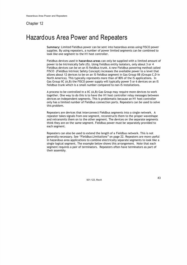
Figure 12.1: Repeaters with FISCO power supplies
Suppose Fieldbus segments 2, 3, and 4 are in a hazardous area. Each segment has 5
devices that need to communicate with each other and with devices on the other
segments. Three repeaters with built-in FISCO power supplies are used as shown. All
the data packets sent by any one of the Fieldbus devices appear on all segmentsincluding segment 1. The H1 host controller needs to have only one Fieldbus port. To
the host and to each of the devices, data transmission and reception appears to be on a
single segment. In reality, they are on separate physical segments. Each segment is
individually powered and terminated in the same way as any other Fieldbus segment.
501-123, RevA44
Current Limiters for Nonincendive Protection
Chapter 13

7/27/2019 Guia Para Uso de Fieldbus
http://slidepdf.com/reader/full/guia-para-uso-de-fieldbus 50/53
45
501-123, RevA
Chapter 13
Current Limiters for Nonincendive Protection
Summary: If current limiters are used on spur connections from the wiring block, the
connected Fieldbus devices in a Div 2 or Zone 2 area can be live-worked without
permits.
Besides protecting a network from a short circuit on a spur from disabling the whole
network, current limiters provide another benefit. They permit a Fieldbus device to be
connected or disconnected from a network in a hazardous area without:
• Turning off the power to the network or
• Having to determine by sniffing if the area is safe.
This is only applicable to Div 2 or Zone 2 areas and only in places that recognize the
nonincendive protection method (not Canada). The requirements for nonincendive
protection are defined in ISA standard 12.12.01-2000. There are four requirements:
1 Nonincendive field wiring needs to be provided. This means that under normal oper-
ating conditions of the equipment, the wiring is not capable of producing an ignition.
Normal operation includes opening, shorting or grounding of the wiring.
2 The Fieldbus device powered from a current limited wiring block output needs to benonincendive. This means the electrical energy stored by the device that can be dis-
sipated outside the device under normal operating conditions needs to be limited.
Normal operation includes opening, shorting or grounding of the field wiring.
3 The spur cable used to connect the Fieldbus device to the wiring block output may
not store enough energy to cause an ignition.
4 The temperature in the Fieldbus device must not exceed a specified value. This is
given by the device’s temperature rating number.
Since a bus-powered Fieldbus device does not generate electrical energy, only the
energy storing components in the device need to be considered. These are capacitors
and inductors that can be discharged into the spur cable. The maximum value of these
energy-storing components Ca and La have been determined for safe operation.
Current Limiters for Nonincendive Protection
7/27/2019 Guia Para Uso de Fieldbus
http://slidepdf.com/reader/full/guia-para-uso-de-fieldbus 51/53
46
501-123, RevA
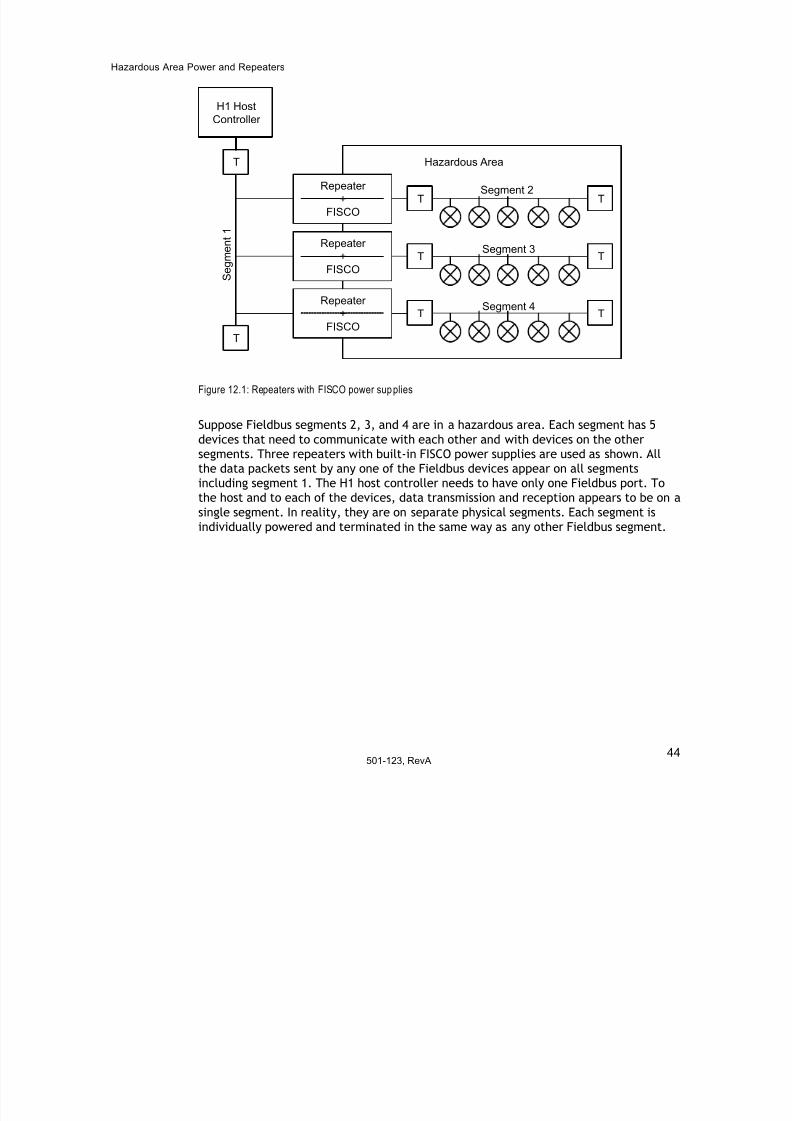
The capacitance and inductance of the spur cable also have to be considered. Standard
Fieldbus cable capacitance is 0.15 nF/m while inductance is 0.54 µH/ m. A
representative Fieldbus cable 120 meters long (the longest suggested spur length) has acapacitance of 24 nF and an inductance of 65 µH.
The capacitance and inductance of the Fieldbus device must also be considered. A
representative value for Fieldbus device’s capacitance is 5 nF. A representative value for
Fieldbus device’s inductance is 10 µH.
Adding the cable and device capacitances and inductances together yields 29 nF and 75
µH. Thus, for normal Fieldbus device operation on the longest spur cable, the values of the energy storing components are well below the safe operation requirements shown in
the table above.
Fieldbus devices intended to operate in hazardous areas have a temperature rating. This
rating is determined in conjunction with the maximum power the device can dissipate.
Since current is limited to 60 mA and the maximum voltage can be 32 Volts, the
maximum power that can be supplied to a device is 1.92 Watts. Generally, devices rated
for Intrinsic Safety use are rated for 1.2 Watts. If this is the case, the Fieldbus powersupply voltage needs to be less than 20 volts. FISCO-rated Fieldbus devices can handle
5.32 Watts and can use Fieldbus power supplies with voltages up to 32 Volts.
Note: Wiring blocks may not be connected to or disconnected from the trunk cable
without determining that the area is safe or without turning off the power to network.
Gas Groups A, C (IIC) C (IIB) D (IIA)
Ca 170 nF 1.22 µF 4.59 µF
La 1.2 mH 3.4 mH 6.3 mH
Glossary
7/27/2019 Guia Para Uso de Fieldbus
http://slidepdf.com/reader/full/guia-para-uso-de-fieldbus 52/53
47501-123, RevA
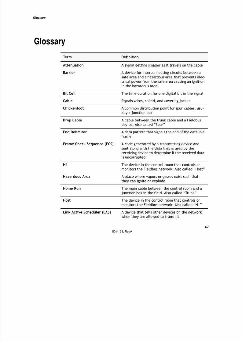
Glossary
Term Definition
Attenuation A signal getting smaller as it travels on the cable
BarrierA device for interconnecting circuits between a
safe area and a hazardous area that prevents elec-
trical power from the safe area causing an ignition
in the hazardous area
Bit Cell The time duration for one digital bit in the signal
Cable Signals wires, shield, and covering jacket
Chickenfoot A common distribution point for spur cables, usu-ally a junction box
Drop Cable A cable between the trunk cable and a Fieldbus
device. Also called “Spur”
End Delimiter A data pattern that signals the end of the data in a
frame
Frame Check Sequence (FCS) A code generated by a transmitting device andsent along with the data that is used by the
receiving device to determine if the received data
is uncorrupted
H1 The device in the control room that controls or
monitors the Fieldbus network. Also called “Host”
Hazardous Area A place where vapors or gasses exist such that
they can ignite or explode
Home Run The main cable between the control room and a
junction box in the field. Also called “Trunk”
Host The device in the control room that controls or
monitors the Fieldbus network. Also called “H1”
Link Active Scheduler (LAS) A device that tells other devices on the network
when they are allowed to transmit
Glossary
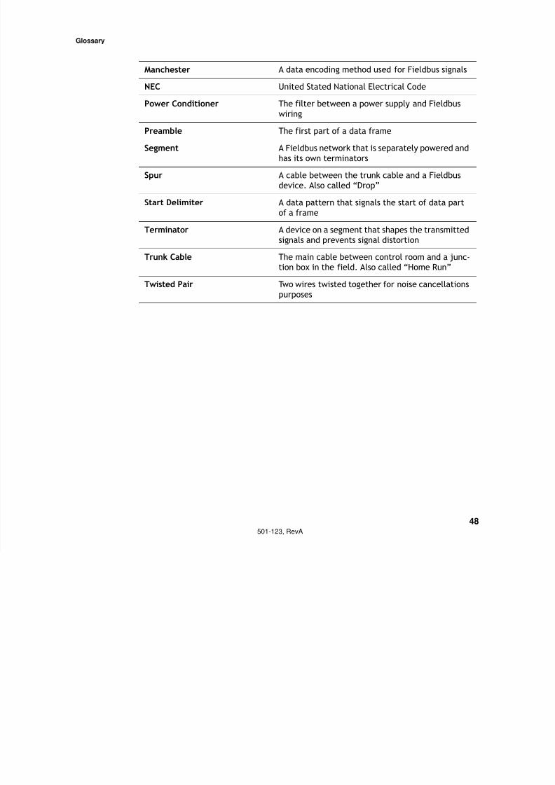
Manchester A data encoding method used for Fieldbus signals
7/27/2019 Guia Para Uso de Fieldbus
http://slidepdf.com/reader/full/guia-para-uso-de-fieldbus 53/53
48501-123, RevA
Manchester A data encoding method used for Fieldbus signals
NEC United Stated National Electrical CodePower Conditioner The filter between a power supply and Fieldbus
wiring
Preamble The first part of a data frame
Segment A Fieldbus network that is separately powered and
has its own terminators
Spur A cable between the trunk cable and a Fieldbus
device. Also called “Drop”
Start Delimiter A data pattern that signals the start of data part
of a frame
Terminator A device on a segment that shapes the transmitted
signals and prevents signal distortion
Trunk Cable The main cable between control room and a junc-
tion box in the field. Also called “Home Run”
Twisted Pair Two wires twisted together for noise cancellations
purposes