turbine
TRANSCRIPT

Introduction to : Steam TurbineIntroduction to : Steam Turbine

A. TURBINE PRINCIPLE
Kalor merupakan aliran energi panas. Energi panas dapat diubah menjadi energi mekanik. Steam turbine merubah energi panas menjadi energi mekanik.
Ketika air dididihkan dan berubah menjadi steam, maka steam akan memiliki jumlah energi yang besar dibandingkan ketika masih berada didalam phasa cair. Memanaskan air didalam kolom tertutup akan menambah tekanan uapnya/vapour pressure.
Tekanan yang dihasilkan akan mendorong steam mengembang melalui nozzle. Steam didorong keluar melalui nozzle pada kecepatan yang sangat tinggi. Aliran steam akan memukul bucket dan mampu membuat bucket tersebut bergerak. Energi mekanik dihasilkan pada saat steam berkecepatan tinggi menghantam bucket dan menyebabkan bucket bergerak .
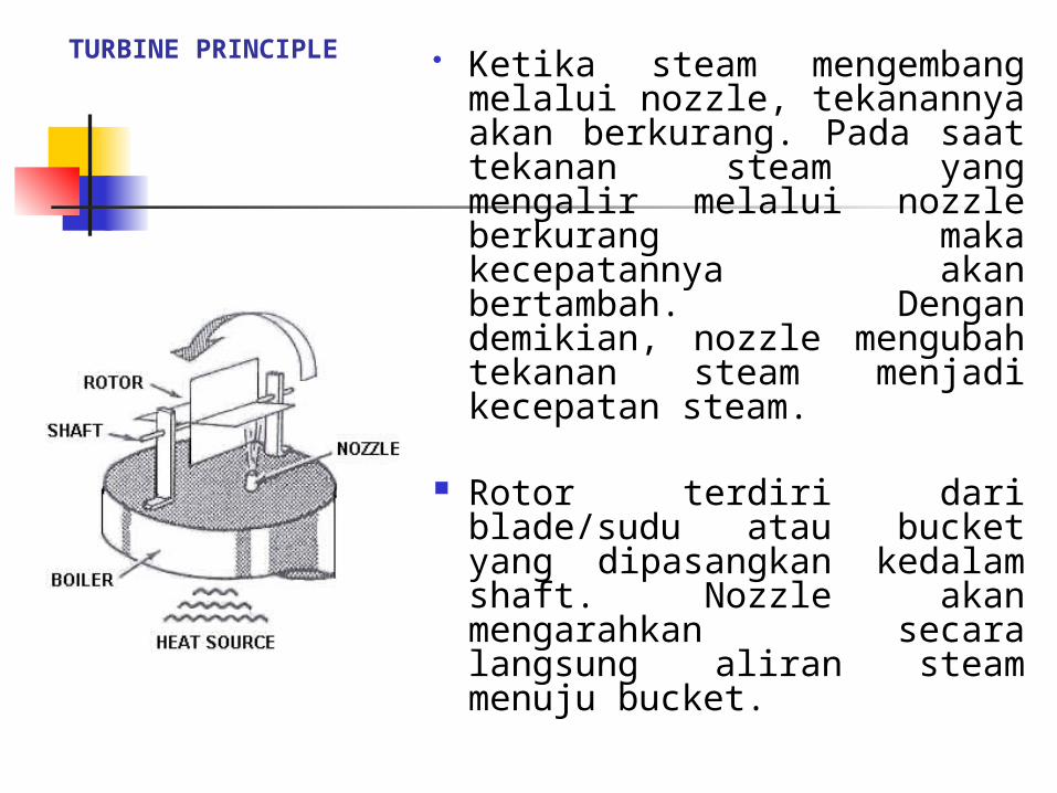
Ketika steam mengembang melalui nozzle, tekanannya akan berkurang. Pada saat tekanan steam yang mengalir melalui nozzle berkurang maka kecepatannya akan bertambah. Dengan demikian, nozzle mengubah tekanan steam menjadi kecepatan steam.
Rotor terdiri dari blade/sudu atau bucket yang dipasangkan kedalam shaft. Nozzle akan mengarahkan secara langsung aliran steam menuju bucket.
TURBINE PRINCIPLE
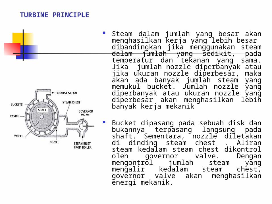
Steam dalam jumlah yang besar akan menghasilkan kerja yang lebih besar dibandingkan jika menggunakan steam dalam jumlah yang sedikit, pada temperatur dan tekanan yang sama. Jika jumlah nozzle diperbanyak atau jika ukuran nozzle diperbesar, maka akan ada banyak jumlah steam yang memukul bucket. Jumlah nozzle yang diperbanyak atau ukuran nozzle yang diperbesar akan menghasilkan lebih banyak kerja mekanik
Bucket dipasang pada sebuah disk dan bukannya terpasang langsung pada shaft. Sementara, nozzle diletakan di dinding steam chest . Aliran steam kedalam steam chest dikontrol oleh governor valve. Dengan mengontrol jumlah steam yang mengalir kedalam steam chest, governor valve akan menghasilkan energi mekanik.
TURBINE PRINCIPLE

Rotor diletakkan didalam metal casing. Agar steam dapat mengalir kedalam casing melalui nozzle, maka tekanan steam didalam casing harus lebih rendah dibandingkan tekanan steam didalam steam chest.
Steam berkecepatan tinggi yang diarahkan menuju bucket lebih merupakan sebagai gaya impelling yang mengakibatkan rotor untuk berputar. Karena turbin memanfaatkan steam impelling pada bucket untuk memutar rotor, turbin jenis ini dekenal sebagai turbine impulse
TURBINE PRINCIPLE

Karena hanya ada sedikit beban pada turbin A maka turbin A membutuhkan sedikit energi dibandingkan turbin B untuk melaksanakan fungsinya. Cara paling tepat untuk menambah tenaga pada turbin adalah dengan mengizinkan lebih banyak steam ke dalam steam chest. Ketika energi yang dibutuhkan lebih banyak, governor valve akan terbuka dan membiarkan lebih banyak steam ke dalam steam chest
Jika beban pada shaft bertambah tetapi aliran steam tidak bertambah, maka kecepatan rotor akan berkurang. Membuka control valve akan menambah kecepatan rotor. Kecepatan rotor juga akan bertambah pada saat beban pada shaft dikurangi. Kecepatan shaft akan bergantung kepada :1. Jumlah beban pada shaft dan2. Jumlah aliran steam ke dalam steam chest
TURBINE PRINCIPLE

When pressure is reduced in one stage only, a turbine is called single stage. If steam pressure is reduced in more than one stage the turbine is called multi-stage. All of the stages are located in one casing. Steam leaves the turbine through the exhaust
On the drawing below, all the wheels are mounted on one shaft. Each stage is isolated by a diaphragm which holds the nozzle.
TURBINE PRINCIPLE
SINGLE DAN MULTISTAGE TURBINE

Instead of one large nozzle, a row of smaller nozzles can be used. There is one row of nozzles per stage on the drawing below
A turbine designed for a high inlet pressure and low exhaust pressure generally has its pressure reduced in several stages. Turbine having large pressure drops between inlet and exhaust are usually multi stage turbines.
Steam expanding from stage to stage increases in volume. To provide for the larger volume in the later stages, the buckets are longer. In rotor B below, the buckets on the last wheel are longer than buckets on the first wheel.

Stationary buckets
The row of nozzles directs steam at the first row of buckets. As the steam leaves the buckets, it is moving in the opposite direction from the moving buckets.
In order to move a second row of buckets in the same direction as the first, the steam must be redirected. Between the two rows of moving buckets is a row of stationary buckets which redirect into another row of moving buckets.
The stationary buckets do no change the pressure of the steam jets any great extent and they are no like a row of nozzle.

Reaction turbine
A reaction turbine has a large portion of the expansion occurring in the buckets or blading of the wheel. A turbine having a large amount of expansion occurring in the wheel blading is a reaction turbine.
The reaction turbine have no stationary nozzles. All the pressure drop occurs in the wheel or rotor. The turbine blading acts like moving nozzles.
In the reaction turbine, some or all expansion occurs in the buckets mounted on the rotor.
Normally, reaction turbines, like impulse turbines have stationary nozzles, but in the reaction turbine, part of the expansion occurs in the buckets.
Reaction turbines, although sometimes more efficient than impulse turbines, require more stages than impulse turbines. They are seldom used as pump or compressor drivers.
Condensing and Non condensing turbines
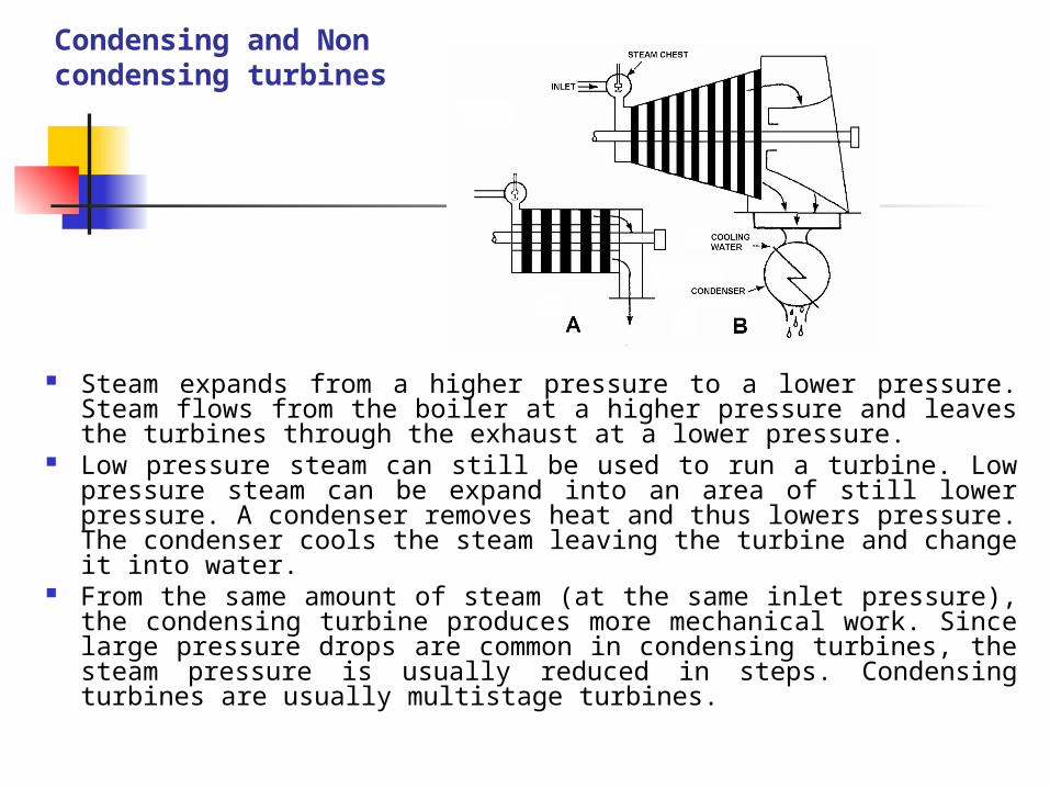
Steam expands from a higher pressure to a lower pressure. Steam flows from the boiler at a higher pressure and leaves the turbines through the exhaust at a lower pressure.
Low pressure steam can still be used to run a turbine. Low pressure steam can be expand into an area of still lower pressure. A condenser removes heat and thus lowers pressure. The condenser cools the steam leaving the turbine and change it into water.
From the same amount of steam (at the same inlet pressure), the condensing turbine produces more mechanical work. Since large pressure drops are common in condensing turbines, the steam pressure is usually reduced in steps. Condensing turbines are usually multistage turbines.
Extraction and induction
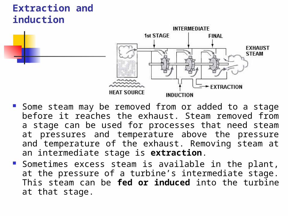
Some steam may be removed from or added to a stage before it reaches the exhaust. Steam removed from a stage can be used for processes that need steam at pressures and temperature above the pressure and temperature of the exhaust. Removing steam at an intermediate stage is extraction.
Sometimes excess steam is available in the plant, at the pressure of a turbine’s intermediate stage. This steam can be fed or induced into the turbine at that stage.

B. GOVERNORS
The governor valve regulates the amount of steam allowed into the turbine and the amount of mechanical work produced. The speed of the driven equipment must be controlled to perform its operating function. The governor valve is used to control turbine speed.
The governor is a mechanism which opens and closes the governor valve at which the speed of turbine will be controlled by the governor
If the turbine starts to speed up or slow down, its speed must be brought back to normal. The governor correct for changes in speed. The fly-ball are held together by the force of a spring. As the governor turns, the spinning (centrifugal) force moves the fly-ball farther together. At low speed, the force of the spring keeps the fly-ball together. Meanwhile, at higher speed, the fly-ball move farther apart. The faster the governor turns, the farther apart the fly-balls move
Direct Acting Fly-ball Governor
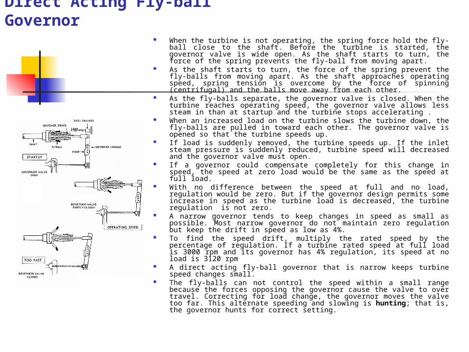
When the turbine is not operating, the spring force hold the fly-ball close to the shaft. Before the turbine is started, the governor valve is wide open. As the shaft starts to turn, the force of the spring prevents the fly-ball from moving apart.
As the shaft starts to turn, the force of the spring prevent the fly-balls from moving apart. As the shaft approaches operating speed, spring tension is overcome by the force of spinning (centrifugal) and the balls move away from each other.
As the fly-balls separate, the governor valve is closed. When the turbine reaches operating speed, the governor valve allows less steam in than at startup and the turbine stops accelerating .
When an increased load on the turbine slows the turbine down, the fly-balls are pulled in toward each other. The governor valve is opened so that the turbine speeds up.
If load is suddenly removed, the turbine speeds up. If the inlet steam pressure is suddenly reduced, turbine speed will decreased and the governor valve must open.
If a governor could compensate completely for this change in speed, the speed at zero load would be the same as the speed at full load.
With no difference between the speed at full and no load, regulation would be zero. But if the governor design permits some increase in speed as the turbine load is decreased, the turbine regulation is not zero.
A narrow governor tends to keep changes in speed as small as possible. Most narrow governor do not maintain zero regulation but keep the drift in speed as low as 4%.
To find the speed drift, multiply the rated speed by the percentage of regulation. If a turbine rated speed at full load is 3000 rpm and its governor has 4% regulation, its speed at no load is 3120 rpm
A direct acting fly-ball governor that is narrow keeps turbine speed changes small.
The fly-balls can not control the speed within a small range because the forces opposing the governor cause the valve to over travel. Correcting for load change, the governor moves the valve too far. This alternate speeding and slowing is hunting; that is, the governor hunts for correct setting.

Hydraulic Governor
To regulate turbine speed, the hydraulic governor uses an oil pump in place of fly-balls which is connected directly to the turbine shaft.
When the turbine is not running, the oil pump puts no pressure into the hydraulic piping. With no pressure on the governor valve, the valve remains open.
As the shaft turn, oil pumped into the piping to the valve. Most of the oil passes out of the leak-off and returns to the reservoir to provide a constant supply of oil to and from the oil pump.
The governor valve is connected to a flexible diaphragm. Change in oil pressure adjust the valve. When the turbine speeds up, more oil is pumped. The oil pressure goes up.
The increased pressure acts on the diaphragm to close the valve. If more load is placed on the turbine, the turbine and the oil pump slow down. Oil pressure goes down and the valve opens.
If oil pressure in the hydraulic system is lost, the governor valve moves to a fully open position. Thus if the hydraulic system fails while the turbine is running, the turbine over speeds.
Temperature affect the viscosity (thickness) of the oil. A change in oil temperature may affect the governor valve setting. Temperature must be controlled. Too much hot thin oil passes through the oil leak-off so that sufficient oil pressure does not build up in the system and the turbine operates at too high a speed.
Cold thick oil pumps very well and not enough of it passes through the leak-off. Pressure in the hydraulic system becomes too great and tends to close the governor valve.
Hydraulic governor are well suited to high speed use. A high speed turbine works best with a hydraulic governor
Since temperature changes can affect the adjustment of the hydraulic governor, hydraulic governor are usually broad governors
A board governor does not move the valve as far to correct a small change in speed as a narrow governor does. Only a large speed change causes the broad governor to move the valve from the opened to the closed position.

Oil Relay Governor The oil relay governor combines the feature of the hydraulic and the fly-ball governor
Oil pressure operates a piston. The spring keeps the piston in place until a change in oil piston pressure acts on the piston.
Fly-balls position the pilot valve that control the oil flowing through the oil inlet and the oil pressure of the oil relay.
At normal operating speed, both the oil inlet and outlet are partially open. But when the governor valve must open to compensate for an increased load, the fly-ball reduce the outlet opening and increase the inlet opening.
To close the governor valve, the fly-ball reduce the inlet opening and increase the outlet opening. Unless the inlet is fully open or fully closed, oil constantly circulates through the relay system, regardless of the setting. Oil from the outlet connection is returned to an oil reservoir to be pumped into the hydraulic system again.
If oil pressure is suddenly lost (through failure of the oil pump, for example), the spring forces the piston to close the valve. With the oil relay governor, loss of oil pressure does not cause the turbine to over speed as with the hydraulic governor
The oil relay governor uses hydraulic force to move the valve so that it has more power than a fly-ball governor by itself.
Of the available governors, the oil relay governor is superior in maintaining a narrow range of speed. Since the fly-ball adjust the speed setting, a change in oil temperature does not affect the turbine speed setting.

Over speed Trip
The governor regulates the turbine under normal condition, but sometimes abnormal condition occur. If all load is suddenly removed from a fully loaded turbine, the turbine may over speed. If the steam is not shut off promptly, the turbine over speed until it flies apart.
A trip pin in the turbine shaft is used to shut off the steam flow in an emergency. At normal speeds the trip pin remains inside the shaft. The pin consist of an unbalanced weight held in the shaft by a spring. If the turbine over speed, the pin is ejected from the shaft by centrifugal force (force of rotation).

When the turbine over speed, the extended pin strikes the over speed trip latch. The trigger releases latch. The trigger releases a latch holding the trip lever, which is then pulled down by a spring. The force of the spring closes the trip valve. The trip valve closes and cuts off the steam flow to the steam chest. The turbine then stop. Unlike governors (which are self correcting), the over speed trip mechanism must be reset after the turbine stop.

Large trip valves use oil under pressure to open them and hold them open. The spring loaded valve is held open by the pressure of the oil.
When the turbine over speeds and the trip pin is ejected, the pin triggers a latch as in figure 18 above. The latch open the oil dump valve.
The force of the spring ejects the oil from the cylinder and the trip valve slams shut. As with the direct acting trip, the mechanism must be reset after the turbine has slowed down.
Over speed trip pin are set to act at speed 10 to 15% over the maximum turbine speed. If the turbine over speed 8% over the maximum, the pin is not ejected from the shaft.