seismic performances of high rise r/c frame … · seismic performances of high rise r/c frame...
TRANSCRIPT

SEISMIC PERFORMANCES OF HIGH RISE R/C FRAME STRUCTURES WITH ADDED BUCKLING RESTRAINED BRACE
ELEMENTS
I. Imran, M. Moestopo, D. Purba, A. Watanabe, T. Hikino, and D. Siringoringo
ABSTRAK
Konstruksi gedung bertingkat tinggi sebagai infrastruktur pendukung bagi pertumbuhan ekonomi meningkat jumlahnya secara signifikan di banyak kota-kota besar di Indonesia. Di Indonesia, banyak gedung bertingkat tinggi dibangun menggunakan material beton bertulang. Sistem struktur tunggal yang paling popular digunakan adalah sistem rangka pemikul momen. Namun, dengan banyak wilayah Indonesia yang memiliki tingkat kegempaan yang tinggi, maka penggunaan sistem rangka pemikul momen tunggal dibatasi, khususnya untuk bangunan tinggi. Fleksibelitas sistem struktur yang dihasilkannya menyebabkan tambahan total simpangan lateral akibat beban gempa. Dalam pelaksanaannya, struktur dinding geser umum ditambahkan pada gedung bertingkat tinggi yang lebih dari 15 lantai untuk membatasi simpangan lateral gempa. Metoda lainnya yang dapat digunakan untuk membatasi simpangan lateral pada gedung tingkat tinggi adalah dengan menambahkan sistem rangka baja dengan bresing terkekang tekuk pada posisi tertentu di gedung rangka penahan momen. Di Jepang, teknologi ini telah berkembang cukup signifikan. Salah satu sistem yang banyak dipakai di Jepang adalah UBB (Unbonded Brace) Jurnal ini menampilkan sebuah studi penggunakan bresing terkekang tekuk pada gedung beton bertulang bertingkat tinggi. Pada studi, gedung perkantoran 20 lantai yang berlokasi di wilayah dengan tingkat kegempaan yang tinggi akan dirancang. Terdapat dua tipe perancangan bangunan yang akan ditinjau, yakni bangunan dengan bresing terkekang tekuk, dan bangunan tanpa bresing terkekang tekuk. Tipe struktur yang digunakan untuk bangunan ini adalah sistem rangka pemikul momen khusus. Kinerja seismik bangunan akan ditinjau menggunakan analisa nonlinier riwayat waktu. Tujuh pergerakan tanah yang telah terskalakan akan digunakan untuk analisa studi ii. Dalam analisanya, kinerja bangunan dengan bresing terkekang tekuk dan tanpa bresing terkekang tekuk akan dibandingkan. Berdasarkan hasil yang didapatkan, penggunaan sistem bresing terkekang tekuk dalam perancangan gedung beton bertulang bertingkat tinggi untuk wilayang dengan tingkat kegempaan tinggi di Indonesia dapat digunakan. KATA KUNCI: daktilitas, analisa riwayat waktu non-linier, desain berbasis kinerja ABSTRACT Construction of high rise buildings as supporting infrastructures for economic growth has increased significantly in numbers in many big cities in Indonesia. In Indonesia, most of high rise buildings are constructed using reinforced concrete materials. The most popular single structural system being adopted in this case is moment resisting frames. However, as many regions in Indonesia have high seismicity, then the use of single moment resisting frames, especially for tall buildings, are becoming restricted. This is due to the flexibilty of the structural system, causing the excessive resulting lateral drift under seismic forces. In practice, structural walls are commonly added in high rise buildings with more than 15 storeys, in order to limit the seismic lateral drift. Other approach that can be used to limit the lateral drift in high rise buildings is by adding buckling restrained brace (BRB) elements in certain locations in moment resisting frame buildings. In Japan, this technology has developed quite significantly. One of the system that is widely used in Japan is UBB (Unbonded Brace). This paper present a study on the use of BRB elements in high rise r/c frame buildings. In the study, 20 storey office buildings located in region with high seismicity are designed. Two types of building designs will be studied, i.e. the building with BRB and that without BRB. The type of

structure adopted for the buildings is special moment resisting frame. The seismic performances of the buildings are then investigated by performing non-linear inelastic time history analysis. Seven scaled ground motions are used for the analysis. From this analysis, the performance of the buildings with BRB and without BRB will be evaluated and compared. Based on the findings, some recommendations are proposed for the use of BRB in the design of high rise r/c buildings located in regions with high seismicity in Indonesia. KEYWORDS: ductility, non-linear time history analysis, performance based design
SEISMIC PERFORMANCES OF HIGH RISE R/C FRAME STRUCTURES WITH ADDED BUCKLING RESTRAINED BRACE
ELEMENTS
I. Imran, M. Moestopo, D. Purba, A. Watanabe, T. Hikino, and D. Siringoringo
1 INTRODUCTION Conventional earthquake resistant structural systems depend on the strength and ductility to control seismic response. In this system, seismic energy is absorbed by formation of plastic hinges in specific locations that allow structure to deform into an inelastic range without substantially degrading the strength and stiffness of structure. This design principle however, may cause damages to structural and non-structural components which may not be economically to repair. As an alternative, a new strategy named damaged-controlled structure has been proposed. Damage-controlled structure in principle consists of an integrated structural system as a combination of two different structures, the primary structure composed of beams and columns, which aims at resisting the vertical service load, and secondary system of energy dissipating or damage-controlling system that aims at controlling the effects of the lateral forces and deformations resulting from earthquake. The primary structure is designed to behave elastically and to retain its building service functions even during a severe earthquake ground motion, while the secondary system can be repaired or replaced after a severe earthquake ground motion. Damage-controlling system that can be used to limit the lateral drift in high rise buildings is by adding buckling restrained brace (BRB) elements. This paper present a study on the use of BRB elements in high rise r/c frame buildings. From this analysis, the performance of the buildings with BRB and without BRB will be evaluated and compared. Based on the findings, some recommendations are proposed for the use of BRB in the design of high rise r/c buildings located in regions with high seismicity in Indonesia.
2 BUCKLING RESISTANCE BRACED FRAMES: UNBONDED BRACE Buckling restrained brace (BRB) is a passive vibration control device that has been used widely in seismic design and retrofitting of buildings and bridges especially in Japan and the United States. In Japan, the BRB is developed based on the concept of damage-controlled structure [1]. Conventional braced frames have difficulty raising from the difference behaviour between the tensile and compression capacity and degradation of tensile capacity under compressive and cyclic loading. The BRB system is developed to avoid the drawbacks of conventional brace system. Research and development have demonstrated that it is possible to achieve ideal behaviour of elastoplastic yielding

through metallic yielding while restraining buckling in compression by external mechanism. This can be achieved by enclosing a ductile metal core in a continuous concrete filled steel tube. By appropriately selecting the strength of material, area and length of portion of the metallic core, longitudinal deformation of the central yielding core can be controlled and independent from mechanism that restrain lateral and local buckling. As a result, the local buckling behaviour is restrained and large inelastic capacities are attainable [2,3]. This is the main principle of buckling restrained braces. Fig 3 is an example of test results of Unbounded Braced (UBB) that shows a hysteresis loops in tension and compression having equal strength and stiffness in the pre- and post-yield ranges. The results highlight the non-buckling and equal strength performance of BRB. Since introduced in 1980s, BRBs are regarded as dampers and have become viable means of enhancing seismic performance of buildings and bridges in Japan. The use of BRB has been specified in the Japan Society of Seismic Isolation (JSSI) Manual for Design and Construction of Passively-Controlled Buildings in 2005[4]. In the US, BRBs have been code regulated since the release of NEHRP Recommended Provision for Seismic Regulations for New Buildings and Other Structures (FEMA 450-1) in 2003[5]. Application of BRB for new building in Japan has increased significantly since the 1995 Kobe earthquake [6]. Whereas for existing buildings, BRB has been for seismic retrofit and to increase seismic capacity of existing buildings not only steel structure but also reinforced concrete buildings [7,8].
Figure 1 Main concept of damage-controlled design (Wada, 1998)
Restraining tube
Mortar
Yielding bar
Some cross sections used
Figure 2 Schematic diagram of BRB and some cross-sections used
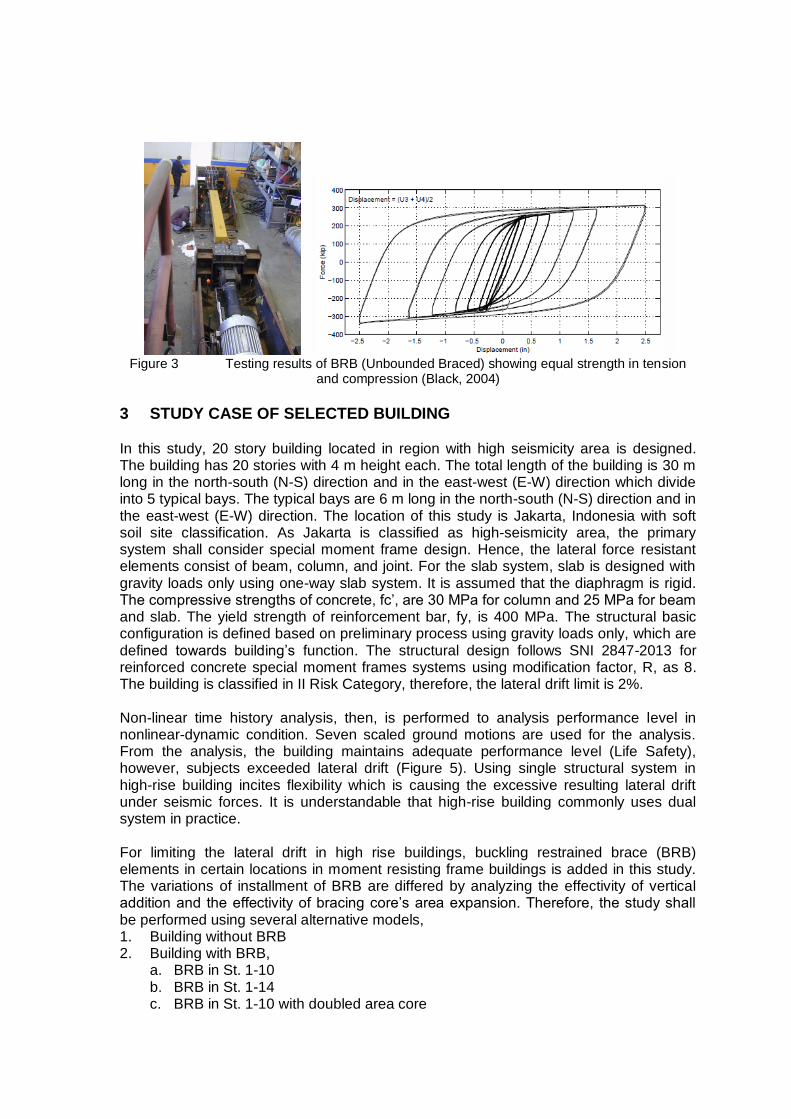
Figure 3 Testing results of BRB (Unbounded Braced) showing equal strength in tension
and compression (Black, 2004)
3 STUDY CASE OF SELECTED BUILDING In this study, 20 story building located in region with high seismicity area is designed. The building has 20 stories with 4 m height each. The total length of the building is 30 m long in the north-south (N-S) direction and in the east-west (E-W) direction which divide into 5 typical bays. The typical bays are 6 m long in the north-south (N-S) direction and in the east-west (E-W) direction. The location of this study is Jakarta, Indonesia with soft soil site classification. As Jakarta is classified as high-seismicity area, the primary system shall consider special moment frame design. Hence, the lateral force resistant elements consist of beam, column, and joint. For the slab system, slab is designed with gravity loads only using one-way slab system. It is assumed that the diaphragm is rigid. The compressive strengths of concrete, fc’, are 30 MPa for column and 25 MPa for beam and slab. The yield strength of reinforcement bar, fy, is 400 MPa. The structural basic configuration is defined based on preliminary process using gravity loads only, which are defined towards building’s function. The structural design follows SNI 2847-2013 for reinforced concrete special moment frames systems using modification factor, R, as 8. The building is classified in II Risk Category, therefore, the lateral drift limit is 2%. Non-linear time history analysis, then, is performed to analysis performance level in nonlinear-dynamic condition. Seven scaled ground motions are used for the analysis. From the analysis, the building maintains adequate performance level (Life Safety), however, subjects exceeded lateral drift (Figure 5). Using single structural system in high-rise building incites flexibility which is causing the excessive resulting lateral drift under seismic forces. It is understandable that high-rise building commonly uses dual system in practice. For limiting the lateral drift in high rise buildings, buckling restrained brace (BRB) elements in certain locations in moment resisting frame buildings is added in this study. The variations of installment of BRB are differed by analyzing the effectivity of vertical addition and the effectivity of bracing core’s area expansion. Therefore, the study shall be performed using several alternative models, 1. Building without BRB 2. Building with BRB,
a. BRB in St. 1-10 b. BRB in St. 1-14 c. BRB in St. 1-10 with doubled area core

There are several controlled beams and columns for analyzing the results, i.e. for beams: B2, B4, and B5; for columns: K3 and K5. See Figure 4.
Figure 4 Structural Configuration and Controlled Beam/Column Reinforcement of Selected
Building

Figure 5 %Drift Comparison without BRB – NLTHA Result
4 DESIGN OF BUCKLING RESISTANCE BRACE The type of BRB for this study is single diagonal type. There are four applied braces in each story with two pair braces resisting lateral drift for each direction. BRB’s dimension is calculated in accordance to required additional story stiffness, Ka, for maintaining accepted lateral drift. The value of Ka is defined by subtracting inelastic story stiffness and targeted story stiffness for drift limit. For this calculation, inelastic story shear shall be estimated from elastic story shear using targeted overstrength, Ωo, for Special Moment Frame System as 3. For this study, modified required additional story stiffness with safety factor – design judgement, Ka’, is 200.000 kN/m. Required additional story stiffness, then, shall be distributed to four braces in one story. Using single diagonal type of BRB, axial stiffness, Kb, for each BRB depends on total number and installment’s geometry of used BRB. For this study, the value of Kb is 144.928 kN/m. According to required axial stiffness for one BRB, core steel element is PL 16x200 mm using A36 and steel tube of BRB is 250x250x6 mm. This design property, then, shall be applied for each study case’s models.
Figure 6 Plan of Installment of Single Diagonal BRB and Design of Single Diagonal BRB for the Study
0
10
20
30
40
50
60
70
80
90
0,00% 0,50% 1,00% 1,50% 2,00% 2,50%
Ele
vation
(m
)
Drift X (%)
%Drift Comparison No BRB
%Drift X - Static, Cd=5.5 % Drift X - 212V5
% Drift X - ABY % Drift X - MEL
%Drift X - MYG013 %Drift X - TCU089
%Drift X - TCU120 %Drift X - TCU136
Drift Limit
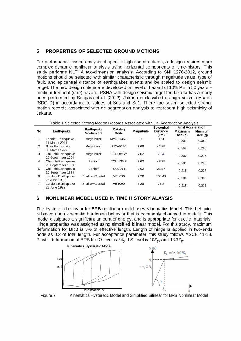
5 PROPERTIES OF SELECTED GROUND MOTIONS For performance-based analysis of specific high-rise structures, a design requires more complex dynamic nonlinear analysis using horizontal components of time-history. This study performs NLTHA two-dimension analysis. According to SNI 1276-2012, ground motions should be selected with similar characteristic through magnitude value, type of fault, and epicentral distance of earthquakes events and be scaled to design seismic target. The new design criteria are developed on level of hazard of 10% PE in 50 years – medium frequent (rare) hazard. PSHA with design seismic target for Jakarta has already been performed by Sengara et al. (2012). Jakarta is classified as high seismicity area (SDC D) in accordance to values of Sds and Sd1. There are seven selected strong-motion records associated with de-aggregation analysis to represent high seismicity of Jakarta.
Table 1 Selected Strong-Motion Records Associated with De-Aggregation Analysis
No Earthquake Earthquake Mechanism
Catalog Code
Magnitude Epicentral Distance
(km)
Final Acceleration
Maximum Acc (g)
Minimum Acc (g)
1 Tohoku Earthquake 11 March 2011
Megathrust MYG013NS 9 170 -0.301 0.352
2 Sitka Earthquake 30 March 1972
Megathrust 212V5090 7.68 42.85 -0.269 0.268
3 Chi - chi Earthquake 20 September 1999
Megathrust TCU089-W 7.62 7.04 -0.300 0.275
4 Chi - chi Earthquake 20 September 1999
Benioff TCU 136 E 7.62 48.75 -0.291 0.293
5 Chi - chi Earthquake 20 September 1999
Benioff TCU120-N 7.62 25.57 -0.215 0.236
6 Landers Earthquake 28 June 1992
Shallow Crustal MEL090 7.28 138.49 -0.306 0.308
7 Landers Earthquake 28 June 1992
Shallow Crustal ABY000 7.28 75.2 -0.215 0.236
6 NONLINEAR MODEL USED IN TIME HISTORY ALAYSIS The hysteretic behavior for BRB nonlinear model uses Kinematics Model. This behavior is based upon kinematic hardening behavior that is commonly observed in metals. This model dissipates a significant amount of energy, and is appropriate for ductile materials. Hinge properties was assigned using simplified bilinear model. For this study, maximum deformation for BRB is 3% of effective length. Length of hinge is applied in two-ends node as 0.2 of total length. For acceptance parameter, this study follows ASCE 41-13.
Plastic deformation of BRB for IO level is , LS level is , and .
Figure 7 Kinematics Hysteretic Model and Simplified Bilinear for BRB Nonlinear Model
Kinematics Hysteretic Model
Forc
e, N
Deformation, δ

Table 2 Parameter of Nonlinear Properties for BRB PL16x200 and BRB Doubled Core Area
Parameter BRB PL16x200 BRB Doubled Core
Area
BRB Axial Stiffness, Kb (kN/m) 144927.536 289855.072 Core Area, A (mm2) 3200 3200 Young Modulus, E (GPa) 205 205 Yield Axial Strees, Ny (kN) 768 1536
Yield Deformation, δy(m) 0.005 0.011
BRB Second Axial Stiffness, K2 (kN/m) 2898.551 2898.551
Maximum Deformation, δmax (%) 3.00% 3.00%
The hysteretic behavior for RC beams and columns nonlinear model uses Takeda Model. This model is similar to the kinematic model, however, uses a degrading hysteretic loop in accordance to the Takeda model (1970). This model dissipates less amount of energy than kinematics models. Therefore, this model appropriately represents concrete model. For this study, nonlinear model is defined based on ASCE 41-13 and is considered as flexure dominated elements. Length of hinge is applied in two-ends node as 0.05 of total length.
Figure 8 Takeda Hysteretic Model for RC Frames Nonlinear Model
7 ANALYSIS RESULTS 7-1 LEVEL OF PERFORMANCE RESULT
Performance level is described by designating the maximum allowable damage state for an identified seismic hazard. There are several stage of level while subjecting a certain hazard level as: Operational, Immediate Occupancy, Life Safety, Near Collapse. According to NEHRP1997, damage parameter is defined by certain range of total interstory drift (I.D.). According to SNI 1276-2012, selected building is classified in Risk Category II, hence, acceptance performance level is Life Safety.
Table 3 Damage Parameters of NEHRP1997
Operational Immediate Occupancy Life Safety Near Collapse
I.D. (%) 0.2 0.5 1.5 2.5
Figure 9 shows the total interstory drift (I.D.) ratio for several installment cases of BRB and initial building without BRB when subjected to ground motions with different accelerations. Performance level, then, shall be identified by I.D. ratio. Overall, four studied models present to maintain an accepted level of performance in Life Safety zone. Addition of BRB conspicuously shows reduction of I.D. ratio as improvement of performance for buildings. The reduction indicates that required additional stiffness is attained effectively.
Takeda Hysteretic Model
Forc
e, N
Rotation, δ

For building with BRB in St. 1-10, seven analysis results show reduction of I.D. ratio, however, the improvement is insignificant compared to other models. For building with BRB in St. 1-14, seven analysis results show that additional BRB improves reduction of I.D. effectively compared to other models. These additions of BRB seemingly provide appropriate required additional stiffness where could accommodate increment of seismic load as result of stiffen periods. For building with BRB in St. 1-10 with doubled core area, seven analysis results show that this configuration maintains an improvement of I.D. ratio, however, is not the most effective alternative. According to the findings, additions of BRB reduce the value of I.D. ratio which lead to improvement of performance level. However, studied parameter is inappropriate to adjust actual effectivity of BRB in the building, hence, further studied parameters shall be investigated.
Figure 9 Comparison of Performance Level Result from seven grounds motion
7-2 TOTAL DISPLACEMENT Figure 10 shows displacement for several installment cases of BRB and initial building without BRB when subjected to ground motions with different accelerations. The reduction indicates that BRB significantly provides appropriate stiffness to maintain lateral displacement. For further evaluation, comparison shall be discussed based upon two cases, i.e. lower half story (St.1-10) and higher half story (St. 11-20). Based on lower half story result, additions of BRB show reduction of displacement in stories. For building with BRB in St. 1-10, seven analysis results show reduction of displacement story significantly compared to initial building. For building with BRB in St. 1-14, seven analysis results show reduction of displacement story significantly compared to initial building, where, insignificantly compared to additions of BRB in St. 1-10. These configurations show slight increment of displacement from building with BRB in St. 1-10. More additions of BRB possibly lead to stiffen periods of building, hence, it is understandable for causing an increase in total dissipation energy. Configuration of BRB along 14 stories improves total dissipation energy of the building with tolerable increment of displacement. For building with doubled core area BRB in St. 1-10, seven analysis results show the most significant reduction of displacement story compared to other models.
1,10%
0,70%
1,17%
0,86% 0,79% 0,79%
0,89% 1,08%
0,63%
0,96%
0,58% 0,55% 0,70%
0,80%
0,95%
0,62%
0,93%
0,53% 0,53% 0,69%
0,79%
1,00%
0,55%
0,91%
0,66% 0,56%
0,73% 0,83%
0,00%
0,50%
1,00%
1,50%
2,00%
2,50%
MYG013 212V5 TCU089 TCU120 TCU136 MEL ABY
Ground Motion
Tota
l I.D
. (%
)
Comparison Performance Level Result
No Bracing Bracing St. 1-10 Bracing St. 1-14 Bracing St. 1-10 A2
C
CP
LS
IO O

Figure 10 Maximum Displacement Result from seven ground motions
Based on higher half story result, additions of BRB, also, show reduction of displacement in stories. For building with BRB in St. 1-10, seven analysis results show reduction of displacement story significantly compared to initial building, however, exceed displacement story of building with BRB in St. 1-14. This condition contradicts lower half story result. The twisted result possibly is led by difference of story stiffness in interchange zone. Compared to higher story, lower half stories shall subject more seismic load as accumulation from above. Therefore, story stiffness designates seismic behavior of building both in total seismic load and total displacement. For building with BRB in St. 1-14, seven analysis results show the most significant reduction of displacement story compared to other models. It is noticed that this configuration maintain story stiffness difference appropriately compared to others. For building with doubled core area BRB in St. 1-10, seven analysis results show reduction of displacement story compared to initial building, however, notice to be insignificant compared to other BRB configurations. This condition, also, contradicts lower half story result, which, subjects higher difference story stiffness in interchange zone.
0
20
40
60
80
100
0 200 400 600 800 1000
Elev
atio
n (
m)
Max Displacement (mm)
Maximum Displacement - MYG013
Max Disp X No Bracing Max Disp X Bracing St 1-10 Max Disp X Bracing St 1-14 Max Disp X Bracing St 1-10 A2
0
20
40
60
80
100
0 200 400 600 El
evat
ion
(m
)
Max Displacement (mm)
Maximum Displacement - 212V5
Max Disp X No Bracing
Max Disp X Bracing St 1-10
Max Disp X Bracing St 1-14
Max Disp X Bracing St 1-10 A2
0
20
40
60
80
100
0 200 400 600 800 1000
Elev
atio
n (
m)
Max Displacement (mm)
Maximum Displacement - TCU089
Max Disp X No Bracing Max Disp X Bracing St 1-10 Max Disp X Bracing St 1-14 Max Disp X Bracing St 1-10 A2
0
20
40
60
80
100
0 200 400 600 800
Elev
atio
n (
m)
Max Displacement (mm)
Maximum Displacement - TCU120 Max Disp X No Bracing Max Disp X Bracing St 1-10 Max Disp X Bracing St 1-14 Max Disp X Bracing St 1-10 A2
0
20
40
60
80
100
0 200 400 600 800
Elev
atio
n (
m)
Max Displacement (mm)
Maximum Displacement - TCU136
Max Disp X No Bracing Max Disp X Bracing St 1-10 Max Disp X Bracing St 1-14 Max Disp X Bracing St 1-10 A2
0
20
40
60
80
100
0 200 400 600 800
Elev
atio
n (
m)
Max Displacement (mm)
Maximum Displacement - MEL
Max Disp X No Bracing
Max Disp X Bracing St 1-10
Max Disp X Bracing St 1-14
Max Disp X Bracing St 1-10 A2
0
20
40
60
80
100
0 200 400 600 800
Elev
atio
n (
m)
Max Displacement (mm)
Maximum Displacement - ABY
Max Disp X No Bracing Max Disp X Bracing St 1-10 Max Disp X Bracing St 1-14 Max Disp X Bracing St 1-10 A2
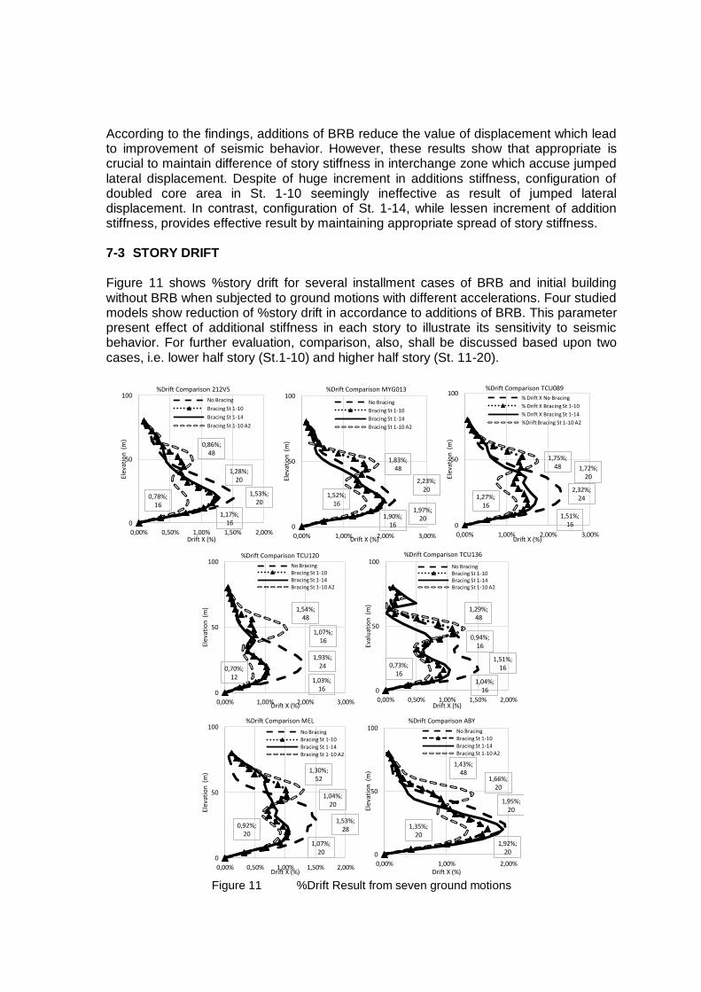
According to the findings, additions of BRB reduce the value of displacement which lead to improvement of seismic behavior. However, these results show that appropriate is crucial to maintain difference of story stiffness in interchange zone which accuse jumped lateral displacement. Despite of huge increment in additions stiffness, configuration of doubled core area in St. 1-10 seemingly ineffective as result of jumped lateral displacement. In contrast, configuration of St. 1-14, while lessen increment of addition stiffness, provides effective result by maintaining appropriate spread of story stiffness. 7-3 STORY DRIFT Figure 11 shows %story drift for several installment cases of BRB and initial building without BRB when subjected to ground motions with different accelerations. Four studied models show reduction of %story drift in accordance to additions of BRB. This parameter present effect of additional stiffness in each story to illustrate its sensitivity to seismic behavior. For further evaluation, comparison, also, shall be discussed based upon two cases, i.e. lower half story (St.1-10) and higher half story (St. 11-20).
Figure 11 %Drift Result from seven ground motions
1,53%; 20
1,17%; 16
1,28%; 20
0,78%; 16
0,86%; 48
0
50
100
0,00% 0,50% 1,00% 1,50% 2,00%
Elev
atio
n (
m)
Drift X (%)
%Drift Comparison 212V5
No Bracing
Bracing St 1-10
Bracing St 1-14
Bracing St 1-10 A2
2,23%; 20
1,90%; 16
1,97%; 20
1,52%; 16
1,83%; 48
0
50
100
0,00% 1,00% 2,00% 3,00%
Elev
atio
n (
m)
Drift X (%)
%Drift Comparison MYG013
No Bracing
Bracing St 1-10
Bracing St 1-14
Bracing St 1-10 A2
2,32%; 24
1,51%; 16
1,72%; 20
1,27%; 16
1,75%; 48
0
50
100
0,00% 1,00% 2,00% 3,00%
Elev
atio
n (
m)
Drift X (%)
%Drift Comparison TCU089
% Drift X No Bracing
% Drift X Bracing St 1-10
% Drift X Bracing St 1-14
%Drift Bracing St 1-10 A2
1,93%; 24
1,03%; 16
1,07%; 16
0,70%; 12
1,54%; 48
0
50
100
0,00% 1,00% 2,00% 3,00%
Elev
atio
n (
m)
Drift X (%)
%Drift Comparison TCU120
No Bracing Bracing St 1-10 Bracing St 1-14 Bracing St 1-10 A2
1,51%; 16
0,94%; 16
1,04%; 16
0,73%; 16
1,29%; 48
0
50
100
0,00% 0,50% 1,00% 1,50% 2,00%
Eval
uat
ion
(m
)
Drift X (%)
%Drift Comparison TCU136
No Bracing Bracing St 1-10 Bracing St 1-14 Bracing St 1-10 A2
1,53%; 28
1,04%; 20
1,07%; 20
0,92%; 20
1,30%; 52
0
50
100
0,00% 0,50% 1,00% 1,50% 2,00%
Elev
atio
n (
m)
Drift X (%)
%Drift Comparison MEL
No Bracing
Bracing St 1-10
Bracing St 1-14
Bracing St 1-10 A2
1,95%; 20
1,66%; 20
1,92%; 20
1,35%; 20
1,43%; 48
0
50
100
0,00% 1,00% 2,00%
Ele
vati
on
(m
)
Drift X (%)
%Drift Comparison ABY
No Bracing
Bracing St 1-10
Bracing St 1-14
Bracing St 1-10 A2

Based on lower half story result, additions of BRB show reduction of %story drift in stories. For building with BRB in St. 1-10, seven analysis results show reduction of %story drift significantly compared to initial building. For building with BRB in St. 1-14, seven analysis results indicate same result to total displacement parameter. This configuration provides reduction of displacement story significantly compared to initial building, where, insignificantly compared to additions of BRB in St. 1-10. There is slight increment lateral drift in El. +20.00 m which is accused by an increase of seismic loads towards RC Frames. For building with doubled core area BRB in St. 1-10, seven analysis results show the most significant reduction of %story drift compared to other models. Based on higher half story result, additions of BRB, also, show reduction of %story drift in each story. For building with BRB in St. 1-10, seven analysis results show reduction significantly compared to initial building, however, exceed %drift story of building with BRB in St. 1-14. Figure 11 presents jumped story drift as result of difference story stiffness in interchange zone. The jumped drift conspicuously exceeds maximum story drift in lower half story. Higher half story seems having softer stiffness than lower half story which possibly develops soft-story mechanism. On other hand, building with BRB in St. 1-14 maintain story stiffness difference appropriately compared to others. For building with doubled core area BRB in St. 1-10, this configuration subjects higher difference story stiffness in interchange zone. Figure 8 presents higher jumped story drift as result of difference story stiffness in interchange zone. This condition possibly develops soft-story mechanism. Despite of huge increment in additional stiffness, configuration of doubled core area in St. 1-10 seemingly ineffective as result of jumped % story drift. In contrast, configuration of St. 1-14, while lessen increment of addition stiffness, provides effective result by maintaining appropriate spread of story stiffness. 7-4 BEAM HINGE RESULT Figure 12 shows the effectivity of BRB for improving rotations in RC beams. BRB manages rotation to reduce the hinge rotation in several beams. There are dropped number for hinge status from Life Safety to Immediate Occupancy. This condition is led by hardening capacity of BRB to dissipate energy, hence, RC beams subjects less seismic loads. In corresponding to number of LS hinges drop to the increment of IO hinges. However, it is noticed that there are decreases of number of elastic beams member. Additional stiffness and difference story stiffness in interchange zone accuse several beams to subject more rotation. For further evaluation, comparison shall be discussed based upon three controlled beams, i.e. B2, B4, and B5. Figure 13 shows increment of inelastic member as IO upon additional BRB. For inelastic member of B2, it is noticed there are increment in number. These conditions are corresponded to an effect of jumped story stiffness in interchange zone. However, the increment is not significant compared to all models, (avg. increment below 10%). Simulation 212V5, TCU089, TCU120, and MEL show huge differences of increment number of inelastic member of B4 along with additions of BRB. It is understandable that the difference is led by several initial members which are changed from LS to IO. Therefore, the increments of inelastic number in B2 and B4 are acceptable. Number of inelastic member for B5 is insignificantly change upon others member. Simulation 212V5, TCU089, TCU120, and MEL, also, show huge difference of increment number of inelastic member of B5 along with additions of BRB as led by several initial members which change from LS to IO.

Figure 12 Local Hinge Result (RC Beams) from seven ground motions
Figure 13 Hinge Result as IO of Controlled Beams from seven ground motions
7-5 COLUMN HINGE RESULT
Comparison shall be discussed based upon three controlled columns, i.e. K3 and K5. Figure 14 shows increment of inelastic member as IO upon additional BRB. RC columns’ rotation shall represent subjected story shear. Increments of inelastic member indicate increases of rotation which correspond subjecting more lateral loads. The additions of BRB stiffen the building, hence, these condition is acceptable. Figure 14, then, show the effects of unaccommodated jumped lateral drift within story as result of difference of
497 477 490 448
598 539 535 551 568
483 482 500
699 723 710 752
472
657 639 649
362
452
485 487
0 0 0 0
130
4 26 0
270 265 233 213
4 0 0 0 0 0 0 0 0 0 0 0
0
200
400
600
800
No Bracing BRB St. 1-10 BRB St. 1-14 BRB St.1-10A2 No Bracing BRB St. 1-10 BRB St. 1-14 BRB St.1-10A2 No Bracing BRB St. 1-10 BRB St. 1-14 BRB St.1-10A2
MYG013 212V5 TCU089
Ground Motion
Tota
l Mem
ber
Local Hinge Result (RC Beam) - 1
Elastic IO LS CP
762 678
632 609 724 692 678 666
616 585 573 551
675 686 655 652
248
522 568 591
468 508 522 534
391
582 627 557
489 514 545 548
190
0 0 0 8 0 0 0
193
33 0
92 36
0 0 0 0 0 0 0 0 0 0 0 0 0 0 0 0 0 0 0
0
200
400
600
800
1000
No Bracing BRB St. 1-10
BRB St. 1-14
BRB St.1-10A2
No Bracing BRB St. 1-10
BRB St. 1-14
BRB St.1-10A2
No Bracing BRB St. 1-10
BRB St. 1-14
BRB St.1-10A2
No Bracing BRB St. 1-10
BRB St. 1-14
BRB St.1-10A2
TCU120 TCU136 MEL ABY
Ground Motion
Tota
l Mem
ber
Local Hinge Result (RC Beam) -2
Elastic IO LS CP
232 250 245 280
172 213 218 205
163
222 217 206
387 393 383 390
250
364 339
363
173 153
219 215
80 80 80 80 50
80 80 80
20 67
29 64
0
100
200
300
400
500
No Bracing BRB St. 1-10 BRB St. 1-14 BRB St.1-10A2 No Bracing BRB St. 1-10 BRB St. 1-14 BRB St.1-10A2 No Bracing BRB St. 1-10 BRB St. 1-14 BRB St.1-10A2
MYG013 212V5 TCU089
Ground Motion
Tota
l Mem
ber
Hinge Result as IO of Controlled Beams - 1
B2-350X650 B4-350X650 B5-350X650
52
108
146 160
76 100 107 122 114
184 191 198
93 103 124 128
166
334 340 349 312
328 333 331
212
318 355
279 316 331 339 338
30
80 80 80 80 80 80 80 65 80 80 80 80 80 80 80
0
100
200
300
400
No Bracing BRB St. 1-10
BRB St. 1-14
BRB St.1-10A2
No Bracing BRB St. 1-10
BRB St. 1-14
BRB St.1-10A2
No Bracing BRB St. 1-10
BRB St. 1-14
BRB St.1-10A2
No Bracing BRB St. 1-10
BRB St. 1-14
BRB St.1-10A2
TCU120 TCU136 MEL ABY
Ground Motion
Tota
l Mem
ber
Hinge Result as IO of Controlled Beams -2 B2-350X650 B4-350X650 B5-350X650
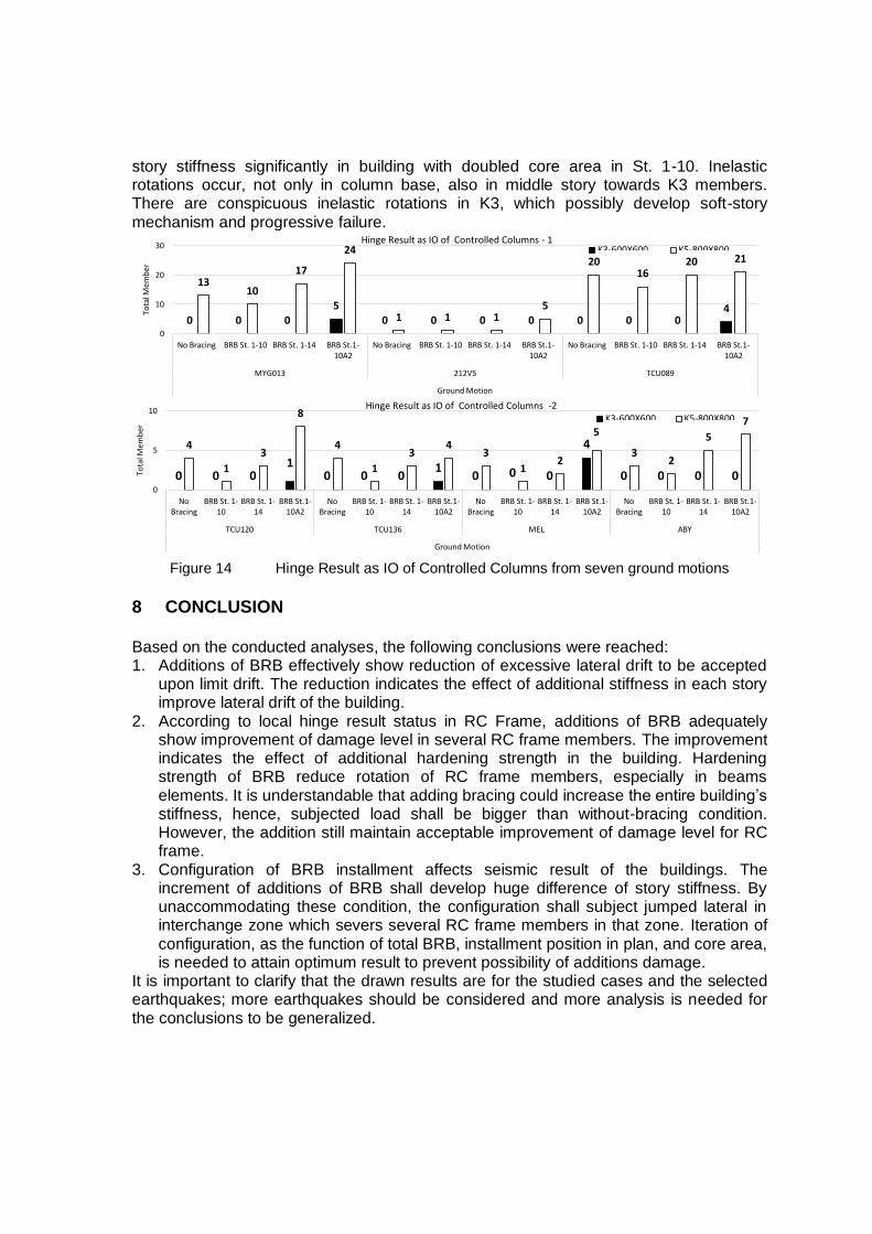
story stiffness significantly in building with doubled core area in St. 1-10. Inelastic rotations occur, not only in column base, also in middle story towards K3 members. There are conspicuous inelastic rotations in K3, which possibly develop soft-story mechanism and progressive failure.
Figure 14 Hinge Result as IO of Controlled Columns from seven ground motions
8 CONCLUSION Based on the conducted analyses, the following conclusions were reached: 1. Additions of BRB effectively show reduction of excessive lateral drift to be accepted
upon limit drift. The reduction indicates the effect of additional stiffness in each story improve lateral drift of the building.
2. According to local hinge result status in RC Frame, additions of BRB adequately show improvement of damage level in several RC frame members. The improvement indicates the effect of additional hardening strength in the building. Hardening strength of BRB reduce rotation of RC frame members, especially in beams elements. It is understandable that adding bracing could increase the entire building’s stiffness, hence, subjected load shall be bigger than without-bracing condition. However, the addition still maintain acceptable improvement of damage level for RC frame.
3. Configuration of BRB installment affects seismic result of the buildings. The increment of additions of BRB shall develop huge difference of story stiffness. By unaccommodating these condition, the configuration shall subject jumped lateral in interchange zone which severs several RC frame members in that zone. Iteration of configuration, as the function of total BRB, installment position in plan, and core area, is needed to attain optimum result to prevent possibility of additions damage.
It is important to clarify that the drawn results are for the studied cases and the selected earthquakes; more earthquakes should be considered and more analysis is needed for the conclusions to be generalized.
0 0 0 5
0 0 0 0 0 0 0 4
13 10
17
24
1 1 1 5
20 16
20 21
0
10
20
30
No Bracing BRB St. 1-10 BRB St. 1-14 BRB St.1-10A2
No Bracing BRB St. 1-10 BRB St. 1-14 BRB St.1-10A2
No Bracing BRB St. 1-10 BRB St. 1-14 BRB St.1-10A2
MYG013 212V5 TCU089
Ground Motion
Tota
l Mem
ber
Hinge Result as IO of Controlled Columns - 1 K3-600X600 K5-800X800
0 0 0 1
0 0 0 1
0 0 0
4
0 0 0 0
4
1
3
8
4
1
3 4
3
1 2
5
3 2
5
7
0
5
10
No Bracing
BRB St. 1-10
BRB St. 1-14
BRB St.1-10A2
No Bracing
BRB St. 1-10
BRB St. 1-14
BRB St.1-10A2
No Bracing
BRB St. 1-10
BRB St. 1-14
BRB St.1-10A2
No Bracing
BRB St. 1-10
BRB St. 1-14
BRB St.1-10A2
TCU120 TCU136 MEL ABY
Ground Motion
Tota
l Mem
ber
Hinge Result as IO of Controlled Columns -2 K3-600X600 K5-800X800

9 REFERENCES
Journals/Textbooks
Black, Cameron J., Nicos Makris, and Ian D. Aiken. "Component testing, seismic evaluation and characterization of buckling-restrained braces." Journal of Structural Engineering 130.6 (2004): 880-894.
Di Sarno, L., and G. Manfredi. "Seismic retrofitting with buckling restrained braces: application to an existing non-ductile RC framed building." Soil Dynamics and Earthquake Engineering 30.11 (2010): 1279-1297.
Kasai, K., et al. "Current status of building passive control in Japan." The 14th World conference on earthquake engineering, Beijing, China. 2008.
Park, R., Paulay, T (1974). Reinforced Concrete Structures. Christchurch: Department of Civil Engineering, University of Canterbury New Zealand.
Sengara, I Wayan (2014). Seismic Hazard Investigation pn De-Aggregation Analysis and Development of Risk-Targeted Ground Motion from Probabilistic Sesimic Hazard (PSHA) For Jakarta, Research Report. Bandung: Geotechnical Engineering Laboratory-Engineering Center for Industry, Institut Teknologi Bandung.
Sutcu, Fatih, Toru Takeuchi, and Ryota Matsui. "Seismic retrofit design method for RC buildings using buckling-restrained braces and steel frames." Journal of Constructional Steel Research 101 (2014): 304-313.
Wada A., Iwata, M., et al. “Damage-controlled design for buildings.” Maruzen, 1998
Watanabe, Atsushi, et al. "Properties of brace encased in buckling-restraining concrete and steel tube." Proceedings of Ninth World Conference on Earthquake Engineering. Vol. 4. 1988.
Provisions/Standards
ASCE 41-13 (2013). Seismic Evaluation and Retrofit of Existing Buildings. Virginia: American Society of Civil Engineers.
FEMA. FEMA 450-1 – NEHRP recommended provisions for seismic regulations for new buildings and other structures – Part 1: provisions. Washington: Building Safety Council of the National Institute of Building Sciences, Federal Emergency Management Agency; 2003.
Manual for Design and Construction of Passively-Controlled Buildings. 2nd ed. Japan Society of Seismic Isolation; 2005 [In Japanese].
Standar Nasional Indonesia. SNI 1726-2012. Tata Cara Perencanaan Ketahanan Gempa Untuk Struktur Bangunan Gedung Nongedung. Badan Standarisasi Nasional. Indonesia.
Standar Nasional Indonesia. SNI 03-2847-2002. Tata Cara Perhitungan Struktur Beton Untuk Bangunan Gedung. Badan Standarisasi Nasional. Indonesia.