gw 2512481257
TRANSCRIPT
7/31/2019 Gw 2512481257
http://slidepdf.com/reader/full/gw-2512481257 1/9
Joyashree Das, Rup Narayan Ray / International Journal of Engineering Research and
Applications (IJERA) ISSN: 2248-9622 www.ijera.com
Vol. 2, Issue 5, September- October 2012, pp.1248-1257
1248 | P a g e
Comparison of 2D and 3D Modeling of Hysteresis Motor with
HTS Element in the Rotor
Joyashree Das (Research Scholar), Rup Narayan Ray (Associate Professor)
Deptt. of Electrical Engg., National Institute of Technology Agartala, Agartala-799055, INDIA.
AbstractThis paper presents 2D and 3D modeling
of hysteresis motor using high temperature
superconducting element Yttrium BariumCopper Oxide (YBCO) in the rotor. These
hysteresis motors aim to improve the
performance in comparison with that of
conventional hysteresis motors. Various
performance parameters of high temperature
superconducting hysteresis motor are computed
from the proposed 2D and 3D modeling. Thehysteresis loop thus obtained is used to find
torque and ac losses for variable applied current.
The measured parameters are compared with the
experimental data and both are found to be ingood agreement. All the simulations are
performed using MATLAB 7.5 and FEM based
COMSOL Multiphysics software.
Keywords: High Temperature Superconducting
(HTS) Hysteresis Motors, Yttrium Barium CopperOxide (YBCO), Finite Element Method, COMSOLMultiphysics.
1. Introduction Now-a-days, high temperature
superconducting (HTS) hysteresis synchronousmotors have received attention because of theireconomical advantage as well as noiselessoperation, small size, self-starting torque and
lightweight compared to the conventional motors[1]. The possibility of incorporating HTS into powerapplications such as electrical motors, generators,bearings and fault current limiters have attractedmuch attention. Hysteresis superconducting motorsoffer the simplest construction. Due to global
interest along with industrial applications, theoptimal performance study of the motor is mostimportant. There are various techniques available toimprove performance of the machine. The literature
study regarding the performance improvement of the machine is presented in this section. Themathematical technique with type-II
superconducting material in the rotor is developedbased on the critical state model for obtaining thecurrent and field distributions within thesuperconducting pieces using the finite element
method [2]. The finite element analysis of hysteresis
motor using magnetization-dependent model isemployed as a hysteresis model. To find the
efficient analysis method, various formulations arecompared for hysteresis region and it is proved thatpseudo-permeability method is most effective [3].D. Inacio et al., investigated the numerical and
experimental techniques for the comparison of bothconventional and high temperature superconductinghysteresis motor. High temperature superconducting
element (YBCO) is used as a rotor of HTShysteresis motor and simulations are performed infinite elements software FLUX2D [4]. The drum
and disc type hysteresis machine withsuperconducting rotors is proposed to obtain theoptimal solution of the machine. For this analysis,finite element modeling software Flux2D was used
[5]. The optimization technique of a coreless dualdiscs hysteresis motor (CDDHM) is developedusing genetic algorithm [6]. A high efficiencyoperation scheme of a hysteresis motor isimplemented which is driven by pulse widthmodulator (PWM) for a short duration over-
excitation [7-9]. Changing magnetic property of therotor using different types of rotor materials is oneof the techniques to improve performance of the
machine. Some of the examples are explained in thissection using different materials.
In 1994, a new class of electromechanicalconverters type hysteresis machines is designed withsolid high temperature superconducting material in
the rotors. The comparative analysis of both thetraditional and superconducting motor performancehas been successfully carried out [10]. A cylindrical
melt-textured YBCO blocks is used in the rotor of hysteresis motor. This motor presents the detailedinvestigation on magnetic processes in these rotors.
It is also found that the construction of electromotors with increased power density is possible if
HTS materials are used [11]. HTS electricalmachines (hysteresis and reluctance machines) with
YBCO materials in the rotor are developed and it isfound that the specific output power of liquidnitrogen cooled HTS motors with bulk YBCO
elements can be higher than the conventional motors[12]. Based on high temperature superconductorssuch as YBCO and Ag-BSCCO elements in the
rotor of various shape, a new type of electricalmotors is implemented. It is observed that the torqueis linearly proportional to total hysteresis losses inthe HTS rotor and independent on the rotor angular
velocity [13-14]. An axial type HTS hysteresis
motor is designed. In this HTS hysteresis motor, therotor consists of BSCCO element with the objective

7/31/2019 Gw 2512481257
http://slidepdf.com/reader/full/gw-2512481257 2/9

7/31/2019 Gw 2512481257
http://slidepdf.com/reader/full/gw-2512481257 3/9
Joyashree Das, Rup Narayan Ray / International Journal of Engineering Research and
Applications (IJERA) ISSN: 2248-9622 www.ijera.com
Vol. 2, Issue 5, September- October 2012, pp.1248-1257
1250 | P a g e
numbers of circular sectors are limited, otherwise
flux leakage increases with increase of the numberof sectors and thus the developed torque of thehysteresis motor will decrease [5].
Fig. 2. Schematic diagram of HTS hysteresis motorin COMSOL MULTIPHYSICS.
2.3. Proposed 3D modeling of HTS hysteresis
motor3D HTS hysteresis motor has the same
materials and specifications as 2D HTS hysteresismotor except the motor is replaced by the 3-dimentional model. The 3D view of HTS hysteresis
motor is shown in Fig. 3.
Fig. 3. 3-dimentional view of HTS hysteresis motorin COMSOL MULTIPHYSICS.
The hysteresis loop is the most importantphenomenon in any hysteresis motor and E-H formulation is the most useful expression of an
electromagnetic field [23]. Therefore, the basicelectromagnetic equation for the HTS hysteresismotor is
t B E
(1)
Where, E is electric field (V/m) and B is magneticflux density (T ).
Therefore, 0t H μσ H 2
(2)
Here, H is magnetic field ( A/m), H = and
2D Hy
Hx
3D Hz
Hy Hx
Where, μ is permeability ( H/m), σ is conductivity
(S/m) and r B is residual flux density (T )
respectively.After determine the value of H , the value of currentdensity ( J ) is obtained using the following equation
H J
(3)
Then the electric field E is calculated using the E-j
power law
nc
J J Ec E
(4)
Where, E c is critical electric field (V/m), J c is critical
current density ( A/m2) and n is power index
respectively.After determining E and J , total ac loss Q isobtained by
s
T
0
E)dsdt (J T Q 1 (5)
Where, T is time period.
Fig. 4. Flow chart
3. Simulation and Experimental ResultsBoth 2D and 3D high temperature
superconducting hysteresis motors are numericallysimulated using the software COMSOLMultiphysics and based on finite element method.

7/31/2019 Gw 2512481257
http://slidepdf.com/reader/full/gw-2512481257 4/9
Joyashree Das, Rup Narayan Ray / International Journal of Engineering Research and
Applications (IJERA) ISSN: 2248-9622 www.ijera.com
Vol. 2, Issue 5, September- October 2012, pp.1248-1257
1251 | P a g e
The E-j power law derived in Eq. (4) and it is used
to calculate the ac losses of HTS hysteresis motor.The specifications of the high temperaturesuperconducting material used in the rotor of the
HTS hysteresis motor is shown in Table 1 and alsothe dimensions of the conventional and HTS
hysteresis motor is shown in Table 2.
Table 1. Specifications of the HTS material used inthe rotor.
Name of the sample YBCO
Outer radius(cm) 2.17
Inner radius(cm) 1.82
Thickness(cm) 0.35
Critical electric field(V/m) 410
Initial Conductivity (S/m) 1610
Critical current density( A/m2) 47
10
Table 2. Dimensions of HTS and conventionalhysteresis motor.
Dimensions HTShysteresis
motor ( cm)
Conventionalhysteresis
motor ( cm)
Stator Outer Radius 4 6
Rotor Outer Radius 2.17 2.8Rotor Inner Radius 1.82 2.625
Air-gap 0.1 0.1
The mesh statistics are applied todiscretized the HTS hysteresis motor into finiteelements. In order to have high level of accuracy theautomatic mesh diagram is not used and a mesh
diagram is designed manually. In this simulation,the numbers of nodes are higher around the air gapand hysteresis rotor. From this mesh statistics,various parameters are known, shown in Table 3.
Table 3. Mesh statistics of HTS hysteresis motor
Mesh statistics 2D 3D
Mesh Triangular Tetrahedral
Number of elements 17432 23564
Number of degrees of freedom
34754 100531
Number of boundaryelements
1234 5012
Solution time (s) 26.219 94.9282
The solution time is changed due to changein the values of various parameters but the numberof elements and number of degrees of freedom will
remain same unless the geometry is changed. Fig. 5
shows the mesh of a 2D and 3D HTS hysteresis
motor.
2D
3D
Fig. 5. Mesh of 2D and 3D HTS hysteresis motor.
3.1. Magnetic flux distribution in HTS hysteresis
motorFig. 6 shows the streamline plot of
magnetic flux density in a 2D and 3D HTShysteresis motor. It is observed that two poles havebeen created in both 2D and 3D HTS hysteresis
motor and also three-dimensional model calculatesmagnetic fields around and inside the hysteresismotor. The transport current of non-HTS stator
produces rotating field in the air gap between thestator and the rotor of the motor, which in turninduces currents in the superconductor and thus theHTS rotor is magnetized. Because of the high
current leading ability of the HTS material, most of the fluxes are trapped in the HTS hysteresis rotor.This phenomenon is shown in the plots of flux
density ( B) and magnetic field ( H ) in 2D and 3DHTS hysteresis motor in Fig. 7 and Fig. 8. From Fig.7 and Fig. 8, it is observed that compared to the
other region the magnetic flux concentration is moreinside the HTS rotor and the flux density andmagnetic field in 3D HTS hysteresis motor is higher

7/31/2019 Gw 2512481257
http://slidepdf.com/reader/full/gw-2512481257 5/9
Joyashree Das, Rup Narayan Ray / International Journal of Engineering Research and
Applications (IJERA) ISSN: 2248-9622 www.ijera.com
Vol. 2, Issue 5, September- October 2012, pp.1248-1257
1252 | P a g e
than 2D HTS hysteresis motor for the same
condition.
2D
3D
Fig. 6. Streamline plot of magnetic flux density of a2D and 3D HTS hysteresis motor.
a
b
c
d
Fig.7. a. Magnetic flux density ( B) plot of a 2D HTS
hysteresis motor, b. Magnetic flux density ( B) (Topview) plot of a 3D HTS hysteresis motor, c. Magnetic flux density ( B) [at (1,1,1)] plot of a 3DHTS hysteresis motor, d. Magnetic flux density ( B)
plot of a 3D HTS hysteresis motor (at level 5).
a
7/31/2019 Gw 2512481257
http://slidepdf.com/reader/full/gw-2512481257 6/9
Joyashree Das, Rup Narayan Ray / International Journal of Engineering Research and
Applications (IJERA) ISSN: 2248-9622 www.ijera.com
Vol. 2, Issue 5, September- October 2012, pp.1248-1257
1253 | P a g e
b
c
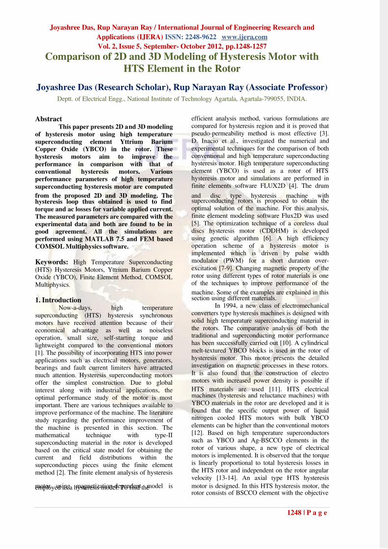
Fig. 8. a. Magnetic field ( H ) plot of a 2D HTShysteresis motor, b. Magnetic field ( H ) [at (1,1,0)]plot of a 3D HTS hysteresis motor, c. Magnetic field
( H ) at (1,1,1) plot of a 3D HTS hysteresis motor.
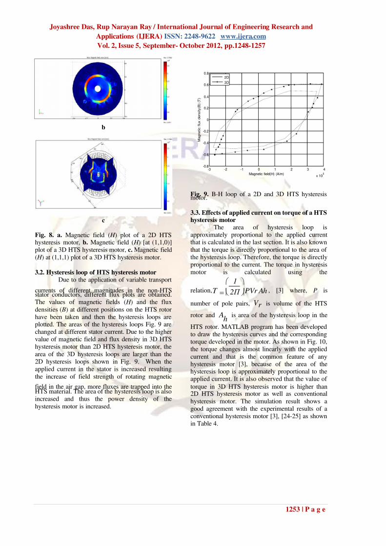
3.2. Hysteresis loop of HTS hysteresis motorDue to the application of variable transport
currents of different magnitudes in the non-HTSstator conductors, different flux plots are obtained.The values of magnetic fields ( H ) and the flux
densities ( B) at different positions on the HTS rotorhave been taken and then the hysteresis loops areplotted. The areas of the hysteresis loops Fig. 9 arechanged at different stator current. Due to the highervalue of magnetic field and flux density in 3D HTShysteresis motor than 2D HTS hysteresis motor, the
area of the 3D hysteresis loops are larger than the2D hysteresis loops shown in Fig. 9. When theapplied current in the stator is increased resulting
the increase of field strength of rotating magnetic
field in the air gap, more fluxes are trapped into theHTS material. The area of the hysteresis loop is alsoincreased and thus the power density of the
hysteresis motor is increased.
-3 -2 -1 0 1 2 3 4
x 105
-0.8
-0.6
-0.4
-0.2
0
0.2
0.4
0.6
0.8
Magnetic field(H) (A/m)
M a g n e t i c f l u x d e n s i t y ( B ) ( T )
2D
3D
Fig. 9. B-H loop of a 2D and 3D HTS hysteresismotor.
3.3. Effects of applied current on torque of a HTShysteresis motor
The area of hysteresis loop isapproximately proportional to the applied currentthat is calculated in the last section. It is also known
that the torque is directly proportional to the area of the hysteresis loop. Therefore, the torque is directlyproportional to the current. The torque in hysteresis
motor is calculated using the
relation, h Ar PV 2 Π
1
T
, [3] where, P is
number of pole pairs, r V is volume of the HTS
rotor andh
A is area of the hysteresis loop in the
HTS rotor. MATLAB program has been developedto draw the hysteresis curves and the correspondingtorque developed in the motor. As shown in Fig. 10,the torque changes almost linearly with the applied
current and that is the common feature of anyhysteresis motor [3], because of the area of thehysteresis loop is approximately proportional to theapplied current. It is also observed that the value of
torque in 3D HTS hysteresis motor is higher than2D HTS hysteresis motor as well as conventional
hysteresis motor. The simulation result shows agood agreement with the experimental results of aconventional hysteresis motor [3], [24-25] as shownin Table 4.

7/31/2019 Gw 2512481257
http://slidepdf.com/reader/full/gw-2512481257 7/9
Joyashree Das, Rup Narayan Ray / International Journal of Engineering Research and
Applications (IJERA) ISSN: 2248-9622 www.ijera.com
Vol. 2, Issue 5, September- October 2012, pp.1248-1257
1254 | P a g e
100 105 110 115 120 125 130 1350.2
0.22
0.24
0.26
0.28
0.3
0.32
0.34
0.36
0.38
Applied current (mA)
T o r q u e ( K g - c m )
Experimental
2D Numerical
3D Numerical
Fig. 10. Torque vs. current of 2D and 3D HTS
hysteresis motor.
Table 4. Comparison between 2D, 3D HTS andconventional hysteresis motor.
3.4. Current density plot in a HTS hysteresis
motorThe Fig. 11 shows the current density plot
of a 2D and 3D HTS hysteresis rotor. Due to thetrapped field effect in the HTS hysteresis rotor, thecurrent density also more in that region but it is notuniform due to the anisotropic conductivity of the
superconducting material. When the trapped fieldsare gradually decreased in the inner part of the HTSrotor, the current density also gradually decreasesand becomes minimum in the inner part of the rotor.
In both of the HTS hysteresis motors, the value of power index (n) is 15 and the value of integral of current density in the 2D HTS rotor
is2 A/m6
10076916.3 and 3D HTS rotor is
8.340536
102
A/m . It is observed that the valueof integral of current density is less compared to the
critical current density (27
/ 104 m A ) and it is
also observed that the current density in 3D HTShysteresis motor is higher than 2D HTS hysteresis
motor.
a
b
c
Fig. 11. a. Current density plot of a 2D, b. currentdensity (top view), c. current density plot 3D HTS
hysteresis rotor.
3.5. Losses in a HTS hysteresis motorIt is known that the torque is directly
proportional to the hysteresis loss in thesuperconducting element [4]. Thus, the loss canalso be calculated from the torque and it is
independent of the field rotational frequency [1].This torque is already calculated in last section.When the applied current is increased, the HTS have
the trend to either have a larger amount of current orgreater volume of current. When the HTS is inmaximum current carrying condition, there is noadditional volume for the new current to flow, thus
the magnitude of current will increase. According to E-j power law, when applied current increases, thecurrent density and electric field is also increased asa result of this the value of AC loss (Q) is alsoincreased following eq. (5), which is proportional tothe product of E and J . The AC losses have been
calculated with different peak values of appliedcurrent, shown in Fig. 12. This is because the E-j power law is used with the power index n=15. From
this plot, it is observed that the AC loss increaseswith the increase of applied current.
Parameter 2D(HTS)
3D(HTS)
Experimental(Conventional)
Torque(Kg-cm)
0.2664 0.2679 0.2647

7/31/2019 Gw 2512481257
http://slidepdf.com/reader/full/gw-2512481257 8/9
Joyashree Das, Rup Narayan Ray / International Journal of Engineering Research and
Applications (IJERA) ISSN: 2248-9622 www.ijera.com
Vol. 2, Issue 5, September- October 2012, pp.1248-1257
1255 | P a g e
100 105 110 115 120 1251.3
1.35
1.4
1.45
1.5
1.55
1.6
1.65
1.7x 10
-3
Applied current (mA)
A C l o s s ( W / m )
2D
3D
Fig. 12. AC loss vs. applied current of 2D and 3DHTS hysteresis motor.
Table 5. Comparison between 2D and 3D HTShysteresis motor.
Parameters 2D 3D
AC loss(W/m) 1.4348e-3 1.4753e-3
Current density
(2
A/mm )
3.076916 8.340531
4. ConclusionIn this work, modeling of 2D and 3D
hysteresis motors using HTS material are presentedand the computed parameters are compared with theexperimental ones. All the simulated results show agood matching with the experimental results and italso shows that the bulk HTS material can traphigher value of magnetic field compared to ferro-magnetic material. The three dimensional model
calculates magnetic fields around and inside themotor and gives better results of motor performance.It has been observed that the developed torqueincreases almost linearly with the increase of the
applied current. Three dimensional modeling of HTS hysteresis motor is proposed which is moreprecise and realistic and very useful in simulations.
The proposed 3D modeling of HTS hysteresis motorgives superior results compared to 2D modeling asfar as the experimental results are concerned.
References[1] Muta, I., Jung, H. J., Hirata, T., Nakamura,
T., Hoshino, T., & Konishi, T. (2001).Fundamental experiments of axial-typeBSCCO-bulk superconducting motormodel. IEEE Transactions On Applied Superconductivity, II (I), 1964-1967.
[2] Barnes, G. J., McCulloch, M. D., & Dew-Hughes, D. (2000). Torque from hysteresismachines with type-II superconducting
segmented rotors. Physica C:
Superconductivity, 331(2), 133-140.[3] Hong-Kyu, Kim, Sun-Ki, Hong, & Hyun-
Kyo, J. (2000). Analysis of hysteresis
motor using finite element method andmagnetization-dependent model. IEEE
Transactions On Magnetics, 36(4), 685-688.
[4] Inacio, D., Inacio S., Pina, J., Goncalves,A., Ventim, Neves, M., & Rodrigues,Leao, A. (2007). Numerical and
experimental comparison of electromechanical properties and efficiencyof HTS and ferromagnetic hysteresismotors. 8
thEuropean Conference On
Applied Superconductivity (EUCAS 2007),
1-7.[5] Rodrigues, Leao, A. (2009). Drum and disc
type hysteresis machines withsuperconducting rotors. IEEE, 55-59.
[6] Sadeghi, H., M., & Darabi, A. (2010).
Optimization of a new type of hysteresismotor using genetic algorithm. EEEIC,
479-482.[7] Kubota, T., Tamura, T., & Kurihara, K.
(2009). High-efficiency operation of PWMinverter-driven hysteresis motor with short-duration overexcitation. Proc. Int. Conf. Elect. Mach. And Systems, 1-4.
[8] Kubota, T., Tamura, T., & Kurihara, K.(2010). New scheme for high-efficiency
operation of PWM inverter-drivenhysteresis motor with short-durationoverexcitation. International Conference
on Electrical Machines, 1-6.
[9] Kubota, T., Tamura, T., & Kurihara, K.(2010). Characteristics of PWM inverter-driven hysteresis motor with short-duration
overexcitation. ICEMS, 1429-1433.[10] Kovalev, L., K., Ilyushin, K., V., Penkin,
V., T., & Kovalev, K., L. (1994).Hysteresis machines with high temperature
superconducting rotors. Elsevier Science, 145-170.
[11] Habisreuther, T., Strasser, T., Gawalek, W.,Goorner,t P., Ilushin, K., V., & Kovalev,L., K. (1997). Magnetic processes inhysteresis motors equipped with melt-textured YBCO. IEEE Transactions On
Applied Superconductivity, 7(2), 900-903.[12] Kovalev, L., K., Ilushin, K., V., Koneev,
S., M., A., Kovalev, K., L., Penkin, V., T.,Poltavets, V., N., Gawalek, W.,Habisreuther, T., Oswald, B., & Best, K., J.(1999). Hysteresis and reluctance electric
machines with bulk HTS rotor elements. IEEE Transactions On Applied
Superconductivity, 9(2), 1261-1264.[13] Kovalev, L., K., Ilushin, K., V., Kovalev,K., L., Penkin, V., T., Poltavets, V., N.,

7/31/2019 Gw 2512481257
http://slidepdf.com/reader/full/gw-2512481257 9/9
Joyashree Das, Rup Narayan Ray / International Journal of Engineering Research and
Applications (IJERA) ISSN: 2248-9622 www.ijera.com
Vol. 2, Issue 5, September- October 2012, pp.1248-1257
1256 | P a g e
Gawalek, W., & Habisreuther, T. et al.
(1998). Hysteresis electrical motors withbulk melt texture YBCO. Material Science
and Engineering, 216-219.
[14] Kovalev, L., K., Ilushin, K., V., Koneev,S., M., A., Kovalev, K., L., Penkin, V., T.,
Modestov, A., K., Larionoff, A., S.,Gawalek, W., & Oswald, B. (2001). HTSelectrical machines with YBCO bulk andAg-BSCCO plate-shape HTS elements:recent results and future development.
Physica C: Superconductivity, 354(1-4), 34-39.
[15] Oswald, B., Krone, M., Strasser, T., Best,K., J., & Soil, M. et al. (2002). Design of
HTS reluctance motors up to severalhundred kW. Physica C:Superconductivity, 372-376 (2), 1513-
1516.[16] Muta, I., Jung, H., Nakamura, T., &
Hoshino, T. (2002). Performance of axial-
type motor with Bi-2223 HTS bulk rotor.Physica C: Superconductivity, 372-376(3), 1531-1534.
[17] Wakui, G., Kurihara, K., & Kubota, T.
(2007). Radial flux type hysteresis motorwith rotor ring of sprayed surface layer.
Electrical Engineering in Japan, 112(4), 132-143.
[18] Match, L., & Morgan, J. (1986). Electromagnetic and Electromechanical
Machines. Wiley & Sons.[19] McCulloch, M., & Dew-Hughes, D.
(1998). Brushless ac machines with hightemperature superconducting rotors.
Material Science and Engineering B53,
211-215.[20] Chun, Y. D., Kim, Y. H., Lee, J., Hong, J.
P., & Lee, J. W. (2001). Finite element
analysis of magnetic field in hightemperature bulk superconductor. IEEE
Trans. On Applied Superconductivity
11(1), 11(2), 2000-2003.[21] Suguira, T., Shashizume, H., and Mika, K.
(1991). Numerical electromagnetic fieldanalysis of type II superconductors. Int J.
of Applied Electromagnetics in Materials
2, 183.[22] Nakamura, T. et al. (2004).
Synchronization of an axial type Bi2223
bulk motor operated in liquid nitrogen.Superconductor Science and Technology17, 1319-1323.
[23] Chari, M. V. K., and Silvester, P. P. (1980).Finite Elements in Electrical and Magnetic
Field Problems. New York: John Willy and
Sons, 31-36. [24] Sun-Ki, Hong, Hong-Kyu, Kim, Hyeong-
Seok, Kim, & Hyun-Kyo, J. (2000). Torquecalculation of hysteresis motor using vector
hysteresis model. IEEE Transactions On
Magnetics, 36(4), 1932-1935.[25] Lee, Hak-Yong, Hahn, Song-yop, Park,
Gwan-Soo, & Lee, Ki-Sik (1998). Torquecomputation of hysteresis motor usingfinite element analysis with asymmetric
two dimensional magnetic permeabilitytensor. IEEE Transactions On Magnetics, 34(5), 3032-3035.