raylan rp ppt
TRANSCRIPT
8/8/2019 Raylan Rp Ppt
http://slidepdf.com/reader/full/raylan-rp-ppt 1/25
Rapid Prototyping Operations
Presentation by:
Raylan Vaz
1RV07ME082VII B
8/8/2019 Raylan Rp Ppt
http://slidepdf.com/reader/full/raylan-rp-ppt 2/25
Introduction
Subtractive processes
Additive process Virtual Prototyping
Applications
8/8/2019 Raylan Rp Ppt
http://slidepdf.com/reader/full/raylan-rp-ppt 3/25
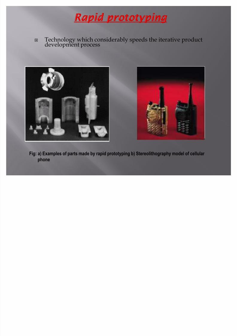
Technology which considerably speeds the iterative productdevelopment process
Fig: a) Examples of parts made by rapid prototyping b) Stereolithography model of cellular
phone
8/8/2019 Raylan Rp Ppt
http://slidepdf.com/reader/full/raylan-rp-ppt 4/25
CAD data files can be manufactured in hours.
Tool for visualization and concept verification.
Prototype used in subsequent manufacturingoperations to obtain final part
Tooling for manufacturing operations can beproduced
8/8/2019 Raylan Rp Ppt
http://slidepdf.com/reader/full/raylan-rp-ppt 5/25
Rapid prototyping is classified to 3-majorgroups
Subtractive ( Removal of material )
Additive ( Adding of material )
Virtual ( Advanced computer basevisualization)
8/8/2019 Raylan Rp Ppt
http://slidepdf.com/reader/full/raylan-rp-ppt 6/25
Subtractive process use computer based Prototype technology tospeed the process
Essential Technologies for subtractive prototyping :
Computer ² based drafting packages ( 3-D representation ofparts)
Interpretation software (Translation of cad file to manufacturingsoftware)
Manufacturing Software (Planning Machining operations)
Computer-Numerical Control Machinery
8/8/2019 Raylan Rp Ppt
http://slidepdf.com/reader/full/raylan-rp-ppt 7/25
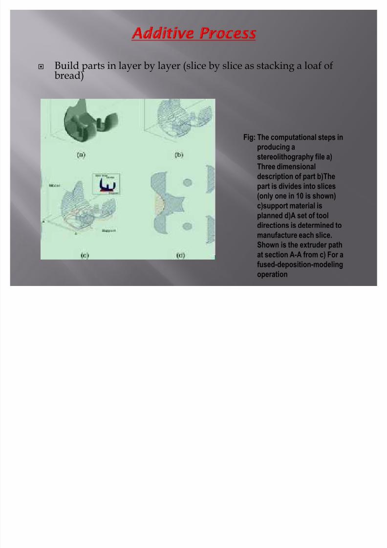
Build parts in layer by layer (slice by slice as stacking a loaf ofbread)
Fig: The computational steps inproducing a
stereolithography file a)
Three dimensional
description of part b)The
part is divides into slices
(only one in 10 is shown)
c)support material isplanned d)A set of tool
directions is determined to
manufacture each slice.
Shown is the extruder path
at section A-A from c) For a
fused-deposition-modeling
operation
8/8/2019 Raylan Rp Ppt
http://slidepdf.com/reader/full/raylan-rp-ppt 8/25
Require elaborate software
1 : Obtain cad file
2 : Computer then constructs slices of a 3-dimensionalpart
3 : slice analyzed and compiled to provide the rapidprototyping machine
4 : setup of the proper unattended and provide roughpart after few hours
5 : Finishing operations and sanding and painting
6:labor intensive and production time varies from fewminutes to few hours
8/8/2019 Raylan Rp Ppt
http://slidepdf.com/reader/full/raylan-rp-ppt 9/25
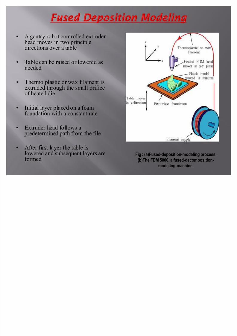
A gantry robot controlled extruder
head moves in two principledirections over a table
Table can be raised or lowered asneeded
Thermo plastic or wax filament isextruded through the small orificeof heated die
Initial layer placed on a foamfoundation with a constant rate
Extruder head follows a predetermined path from the file
After first layer the table islowered and subsequent layers areformed
Fig : (a)Fused-deposition-modeling process.
(b)The FDM 5000, a fused-decomposition-
modeling-machine.
8/8/2019 Raylan Rp Ppt
http://slidepdf.com/reader/full/raylan-rp-ppt 10/25
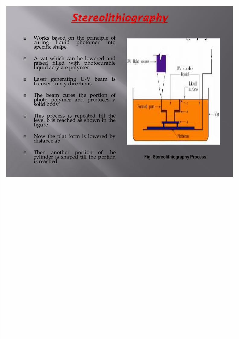
Works based on the principle ofcuring liquid photomer intospecific shape
A vat which can be lowered andraised filled with photocurableliquid acrylate polymer
Laser generating U-V beam is
focused in x-y directions
The beam cures the portion ofphoto polymer and produces asolid body
This process is repeated till thelevel b is reached as shown in the
figure
Now the plat form is lowered bydistance ab
Then another portion of thecylinder is shaped till the portionis reached
Fig :Stereolithiography Process
8/8/2019 Raylan Rp Ppt
http://slidepdf.com/reader/full/raylan-rp-ppt 11/25
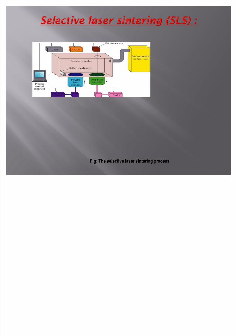
Fig: The selective laser sintering process
8/8/2019 Raylan Rp Ppt
http://slidepdf.com/reader/full/raylan-rp-ppt 12/25
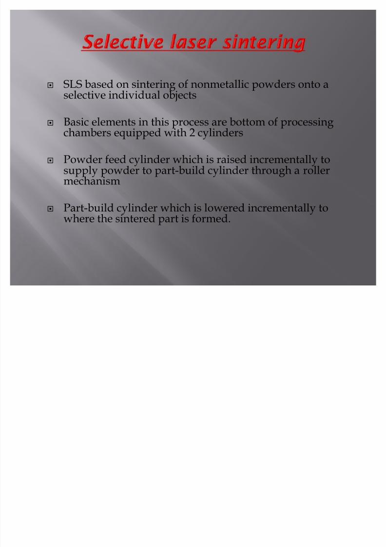
SLS based on sintering of nonmetallic powders onto aselective individual objects
Basic elements in this process are bottom of processing
chambers equipped with 2 cylinders
Powder feed cylinder which is raised incrementally tosupply powder to part-build cylinder through a rollermechanism
Part-build cylinder which is lowered incrementally towhere the sintered part is formed.
8/8/2019 Raylan Rp Ppt
http://slidepdf.com/reader/full/raylan-rp-ppt 13/25
Set of the proper computer files and the initiation ofthe production processes
Machine operate unattended and provide rough
part after few hours
Finishing operations as sanding and painting
Labor intensive & production time varies from fewminutes to few hours
8/8/2019 Raylan Rp Ppt
http://slidepdf.com/reader/full/raylan-rp-ppt 14/25
Layer of powder is first deposited on partbuild cylinders
A laser beam controlled by instruction from3-D file is focused on that layer tracing &sintering a particular cross-section into asolid mass & dust is taken off.
Another layer of powder is now depositedthis cycle is repeated again and dust isshaken off
8/8/2019 Raylan Rp Ppt
http://slidepdf.com/reader/full/raylan-rp-ppt 15/25
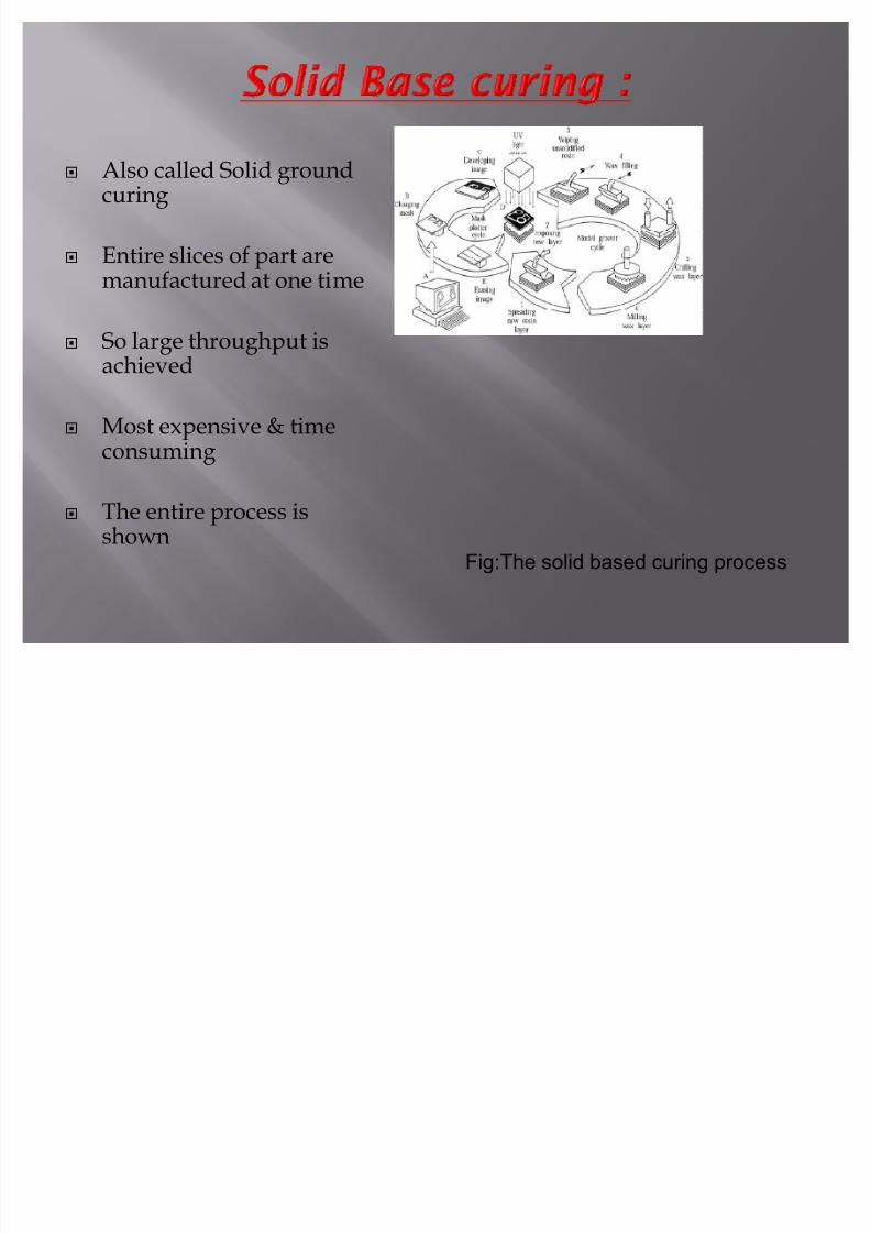
Also called Solid groundcuring
Entire slices of part aremanufactured at one time
So large throughput isachieved
Most expensive & time
consuming
The entire process isshown
Fig:The solid based curing process
8/8/2019 Raylan Rp Ppt
http://slidepdf.com/reader/full/raylan-rp-ppt 16/25
Ballistic particle manufacturing
Stream of material , such as plastic ,ceramic, metal orwax ejected through small orifice at a surface
Mechanism similar to inkjet mechanism ( piezo-electricpump)
Operation repeats similar to other process to form apart with layers of wax deposited on top of each other
Ink jet heat guided by three-axis robot
8/8/2019 Raylan Rp Ppt
http://slidepdf.com/reader/full/raylan-rp-ppt 17/25
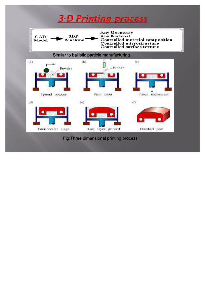
Similar to ballistic particle manufacturingSimilar to ballistic particle manufacturing
Fig:Three dimensional printing process
8/8/2019 Raylan Rp Ppt
http://slidepdf.com/reader/full/raylan-rp-ppt 18/25
Print head deposits an inorganic binder material
Binder directed onto a layer of ceramic metal powder
A piston supporting the powder bed is lower incrementallywith each step a layer is deposited and unified by binder
Commonly used materials ² Aluminum oxide, siliconcarbide,silica and zirconium.
Common part produced by 3-D printing is a ceramic castingshall
Curing around 150 C ² 300 F
Firing ² 1000C ² 1500 C
8/8/2019 Raylan Rp Ppt
http://slidepdf.com/reader/full/raylan-rp-ppt 19/25
Laminated implies laying down of layers which areadhesively bonded to one another
Uses layer of paper or plastic sheets with heat activated glueon one side of the product parts
Excess material to be removed manually
Simplified by preparing the laser to burn perforations incross-sectional pattern
LOM uses sheets as thin as 0.05mm
Compressed paper has appearance and strength of soft wood, and often mistaken for elaborate wood carvings.
8/8/2019 Raylan Rp Ppt
http://slidepdf.com/reader/full/raylan-rp-ppt 20/25
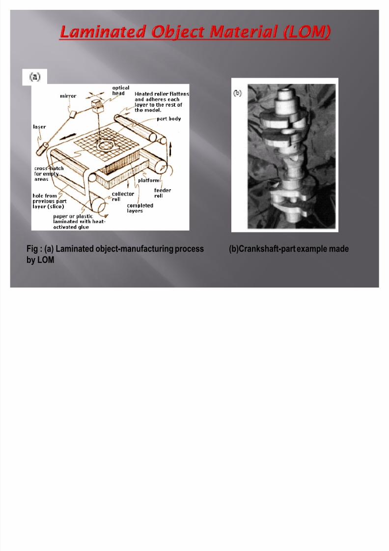
Fig : (a) Laminated object-manufacturing process (b)Crankshaft-part example made
by LOM
8/8/2019 Raylan Rp Ppt
http://slidepdf.com/reader/full/raylan-rp-ppt 21/25
Virtual prototyping (modeling andsimulation of all aspects of a prototype, i.e.mechanical design, kinematics, dynamics,and controls accompanied by a realistic
visualization).
Realizing the best design in the shortestlead-time of complex products/processes
Allows the exotic, unconventional designsbe prototyped, rapidly and cost-effectively
8/8/2019 Raylan Rp Ppt
http://slidepdf.com/reader/full/raylan-rp-ppt 22/25
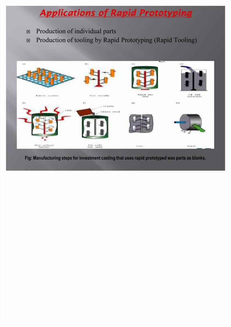
Production of individual parts
Production of tooling by Rapid Prototyping (Rapid Tooling)
Fig: Manufacturing steps for investment casting that uses rapid prototyped wax parts as blanks.
8/8/2019 Raylan Rp Ppt
http://slidepdf.com/reader/full/raylan-rp-ppt 23/25
The term Rapid Tooling (RT) is typically used to describe a process which
either uses a Rapid Prototyping (R P) model as a pattern to create a mold
quickly or uses the Rapid Prototyping process directly to fabricate a tool
for a limited volume of prototypes .
a)Tooling time is much shorter than for a conventional tool. Typically, timeto first articles is below one-fifth that of conventional tooling.
b) Tooling cost is much less than for a conventional tool. Cost can be below
five percent of conventional tooling cost.
c) Tool life is considerably less than for a conventional tool.
d) Tolerances are wider than for a conventional tool.
8/8/2019 Raylan Rp Ppt
http://slidepdf.com/reader/full/raylan-rp-ppt 24/25
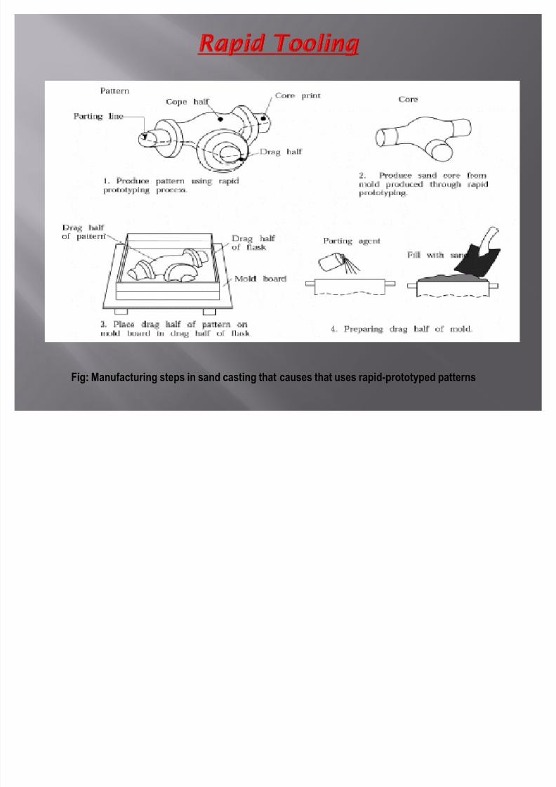
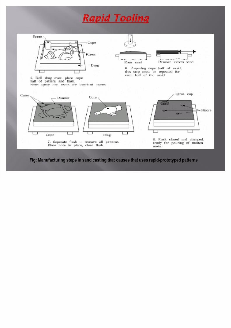
Fig: Manufacturing steps in sand casting that causes that uses rapid-prototyped patterns
8/8/2019 Raylan Rp Ppt
http://slidepdf.com/reader/full/raylan-rp-ppt 25/25
Fig: Manufacturing steps in sand casting that causes that uses rapid-prototyped patterns