estimation of 12 biomass parameters using … · estimation of 12 biomass parameters using...
TRANSCRIPT
01-06-2015
FIG Working Week 2015 1
ESTIMATION OF 12 BIOMASS PARAMETERS USING
TERRESTRIAL LASER SCANNER
Irwan Gumilar1*, Hasanuddin Z. Abidin1, Eko Prasetyo1, Ekus Kustiwa2, Nabila Sofia Eryan Putri1
a Geodesy Research Group ITB
Jln. Ganesha 10 Bandung, Telp. +062-22-2534286,
Email: [email protected] bDirectorate of Forest Land Gazettement, Use Planning and Tenure, Directorate
General of Forestry
OUTLINE
INTRODUCTION1
METHODOLOGY2
ANALYSIS AND DISCUSSION3
CONCLUSION4
01-06-2015
FIG Working Week 2015 2
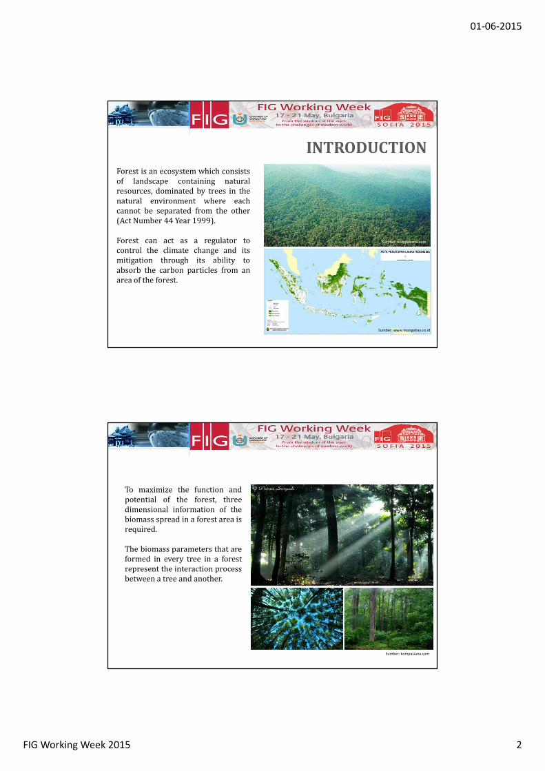
Forest is an ecosystem which consists
of landscape containing natural
resources, dominated by trees in the
natural environment where each
cannot be separated from the other
(Act Number 44 Year 1999).
Forest can act as a regulator to
control the climate change and its
mitigation through its ability to
absorb the carbon particles from an
area of the forest.
INTRODUCTION
Sumber: www.mongabay.co.id
Sumber: kompasiana.com
To maximize the function and
potential of the forest, three
dimensional information of the
biomass spread in a forest area is
required.
The biomass parameters that are
formed in every tree in a forest
represent the interaction process
between a tree and another.
Sumber: kompasiana.com
01-06-2015
FIG Working Week 2015 3
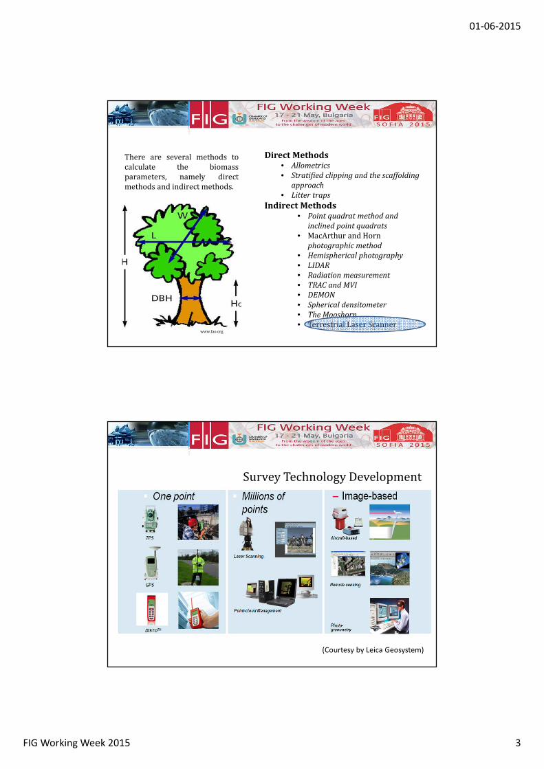
There are several methods to
calculate the biomass
parameters, namely direct
methods and indirect methods.
Direct Methods
• Allometrics
• Stratified clipping and the scaffolding
approach
• Litter traps
Indirect Methods
• Point quadrat method and
inclined point quadrats
• MacArthur and Horn
photographic method
• Hemispherical photography
• LIDAR
• Radiation measurement
• TRAC and MVI
• DEMON
• Spherical densitometer
• The Mooshorn
• Terrestrial Laser Scannerwww.fao.org
(Courtesy by Leica Geosystem)
Survey Technology Development
01-06-2015
FIG Working Week 2015 4
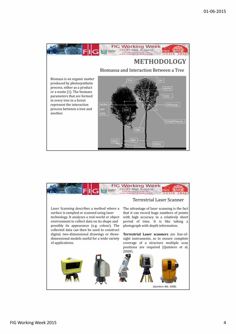
Biomass is an organic matter
produced by photosynthetic
process, either as a product
or a waste [1]. The biomass
parameters that are formed
in every tree in a forest
represent the interaction
process between a tree and
another.
Biomassa and Interaction Between a Tree
METHODOLOGY
Laser Scanning describes a method where a
surface is sampled or scanned using laser
technology. It analyzes a real-world or object
environment to collect data on its shape and
possibly its appearance (e.g. colour). The
collected data can then be used to construct
digital, two-dimensional drawings or three-
dimensional models useful for a wide variety
of applications.
The advantage of laser scanning is the fact
that it can record huge numbers of points
with high accuracy in a relatively short
period of time. It is like taking a
photograph with depth information.
Terrestrial Laser scanners are line-of-
sight instruments, so to ensure complete
coverage of a structure multiple scan
positions are required (Quintero et al,
2008).
(Quintero dkk. 2008).
Terrestrial Laser Scanner
01-06-2015
FIG Working Week 2015 5
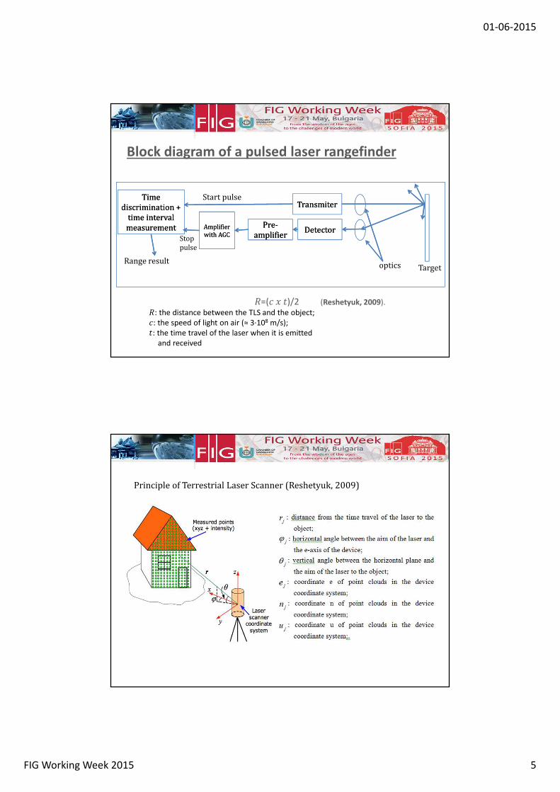
Block diagram of a pulsed laser rangefinder
TransmiterTransmiter
Pre-
amplifier
Pre-
amplifierDetectorDetectorAmplifier
with AGC
Amplifier
with AGC
Time
discrimination +
time interval
measurement
Time
discrimination +
time interval
measurement
Range resultoptics Target
�=(� � �)/2 (Reshetyuk, 2009).
�: the distance between the TLS and the object;
�: the speed of light on air (≈ 3∙108 m/s);
�: the time travel of the laser when it is emitted
and received
Start pulse
Stop
pulse
Principle of Terrestrial Laser Scanner (Reshetyuk, 2009)
01-06-2015
FIG Working Week 2015 6
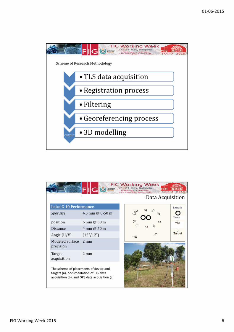
• TLS data acquisition
• Registration process
• Filtering
• Georeferencing process
output • 3D modelling
Scheme of Research Methodology
Data Acquisition
Leica C-10 Performance
Spot size 4.5 mm @ 0-50 m
position 6 mm @ 50 m
Distance 4 mm @ 50 m
Angle (H/V) (12”/12”)
Modeled surface
precision
2 mm
Target
acquisition
2 mm
The scheme of placements of device and
targets (a), documentation of TLS data
acquisition (b), and GPS data acquisition (c)
01-06-2015
FIG Working Week 2015 7
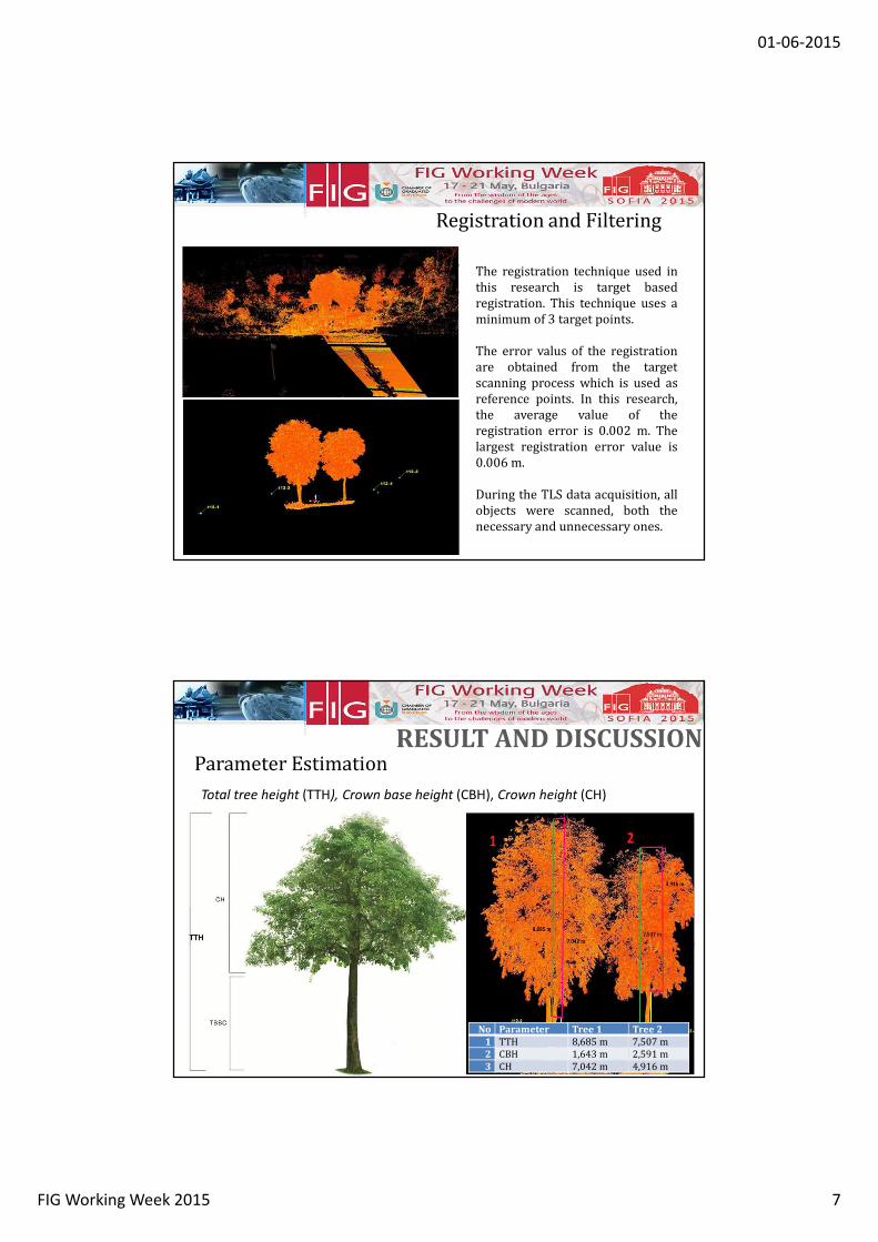
The registration technique used in
this research is target based
registration. This technique uses a
minimum of 3 target points.
The error valus of the registration
are obtained from the target
scanning process which is used as
reference points. In this research,
the average value of the
registration error is 0.002 m. The
largest registration error value is
0.006 m.
During the TLS data acquisition, all
objects were scanned, both the
necessary and unnecessary ones.
Registration and Filtering
Parameter Estimation
Total tree height (TTH), Crown base height (CBH), Crown height (CH)
No Parameter Tree 1 Tree 2
1 TTH 8,685 m 7,507 m
2 CBH 1,643 m 2,591 m
3 CH 7,042 m 4,916 m
RESULT AND DISCUSSION
01-06-2015
FIG Working Week 2015 8
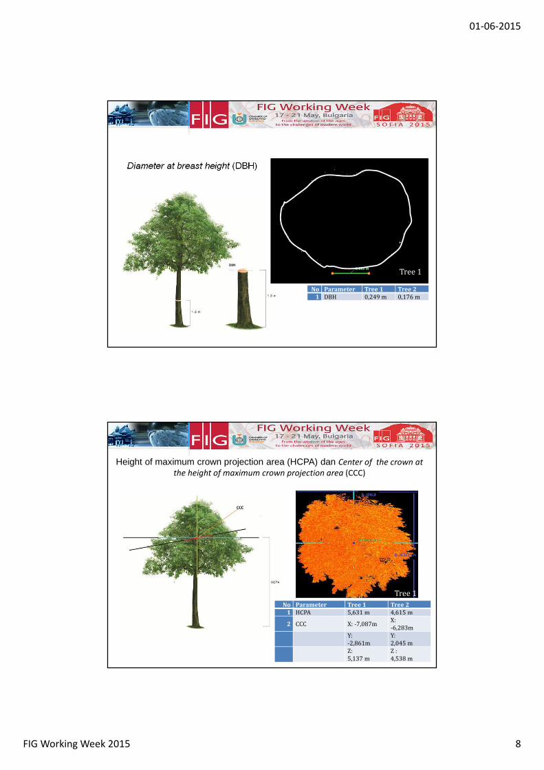
Diameter at breast height (DBH)
No Parameter Tree 1 Tree 2
1 DBH 0,249 m 0,176 m
Tree 1
Height of maximum crown projection area (HCPA) dan Center of the crown at
the height of maximum crown projection area (CCC)
Tree 1No Parameter Tree 1 Tree 2
1 HCPA 5,631 m 4,615 m
2 CCC X: -7,087mX:
-6,283m
Y:
-2,861m
Y:
2,045 m
Z:
5,137 m
Z :
4,538 m
Tree 1
01-06-2015
FIG Working Week 2015 9
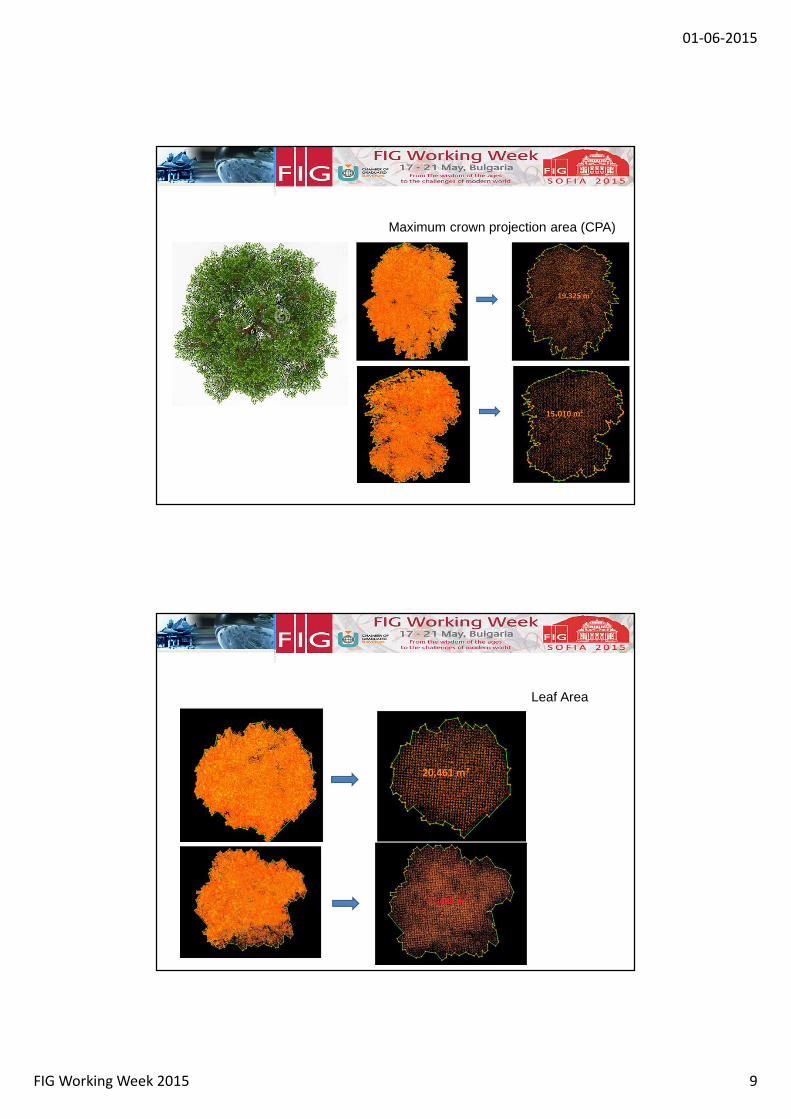
Maximum crown projection area (CPA)
Leaf Area
01-06-2015
FIG Working Week 2015 10
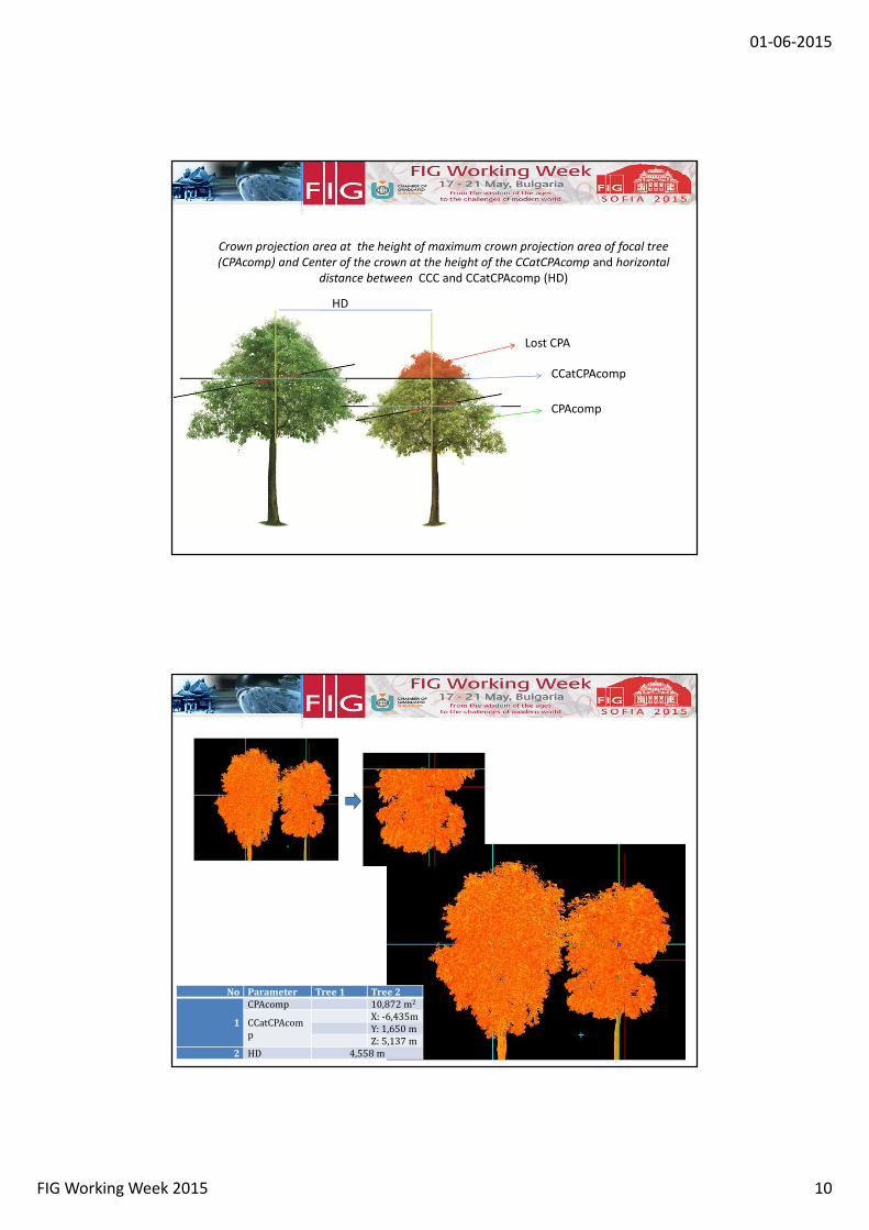
Crown projection area at the height of maximum crown projection area of focal tree
(CPAcomp) and Center of the crown at the height of the CCatCPAcomp and horizontal
distance between CCC and CCatCPAcomp (HD)
CPAcomp
Lost CPA
CCatCPAcomp
HD
No Parameter Tree 1 Tree 2
1
CPAcomp 10,872 m2
CCatCPAcom
p
X: -6,435m
Y: 1,650 m
Z: 5,137 m
2 HD 4,558 m
01-06-2015
FIG Working Week 2015 11
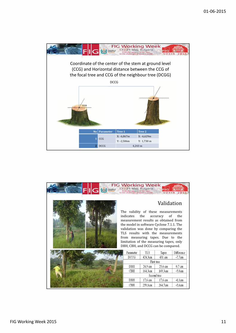
Coordinate of the center of the stem at ground level
(CCG) and Horizontal distance between the CCG of
the focal tree and CCG of the neighbour tree (DCGG)
DCCG
No Parameter Tree 1 Tree 2
1 CCGX: -6,867m X: -6,629m
Y: -2,506m Y: 1,730 m
2 DCCG 4,243 m
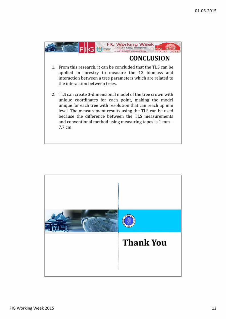
The validity of these measurements
indicates the accuracy of the
measurement results as obtained from
the model in software Cyclone 7.1.1. The
validation was done by comparing the
TLS results with the measurements
from measuring tapes. Due to the
limitation of the measuring tapes, only
DBH, CBH, and DCCG can be compared.
Validation
01-06-2015
FIG Working Week 2015 12
1. From this research, it can be concluded that the TLS can be
applied in forestry to measure the 12 biomass and
interaction between a tree parameters which are related to
the interaction between trees.
2. TLS can create 3-dimensional model of the tree crown with
unique coordinates for each point, making the model
unique for each tree with resolution that can reach up mm
level. The measurement results using the TLS can be used
because the difference between the TLS measurements
and conventional method using measuring tapes is 1 mm –
7,7 cm
CONCLUSION
Thank You