jurnal - eprints.utm.myeprints.utm.my/id/eprint/71199/1/izzatiyusri2016_optimizationofthe... ·...
TRANSCRIPT
78:9 (2016) 13–20 | www.jurnalteknologi.utm.my | eISSN 2180–3722 |
Jurnal
Teknologi
Full Paper
OPTIMIZATION OF THE FORCE CHARACTERISTIC
OF ROTARY MOTION TYPE OF
ELECTROMAGNETIC ACTUATOR BASED ON
FINITE ELEMENT ANALYSIS
Izzati Yusria, Mariam Md Ghazalya*, Esmail Ali Ali Alandolia, Mohd
Fua’ad Rahmatb, Zulkeflee Abdullahc, Mohd Amran Md Alic,
Rahifa Ranoma
aCenter for Robotic and Industrial Automation (CeRIA), Faculty of
Electrical Engineering, Universiti Teknikal Malaysia, Melaka, Hang
Tuah Jaya,76100 Durian Tunggal, Melaka, Malaysia bFaculty of Electrical Engineering, Universiti Teknologi Malaysia,
81310 UTM Johor Bahru, Johor, Malaysia cFaculty of Manufacturing Engineering, Universiti Teknikal Malaysia
Melaka, Hang Tuah Jaya,76100 Durian Tunggal, Melaka, Malaysia
Article history
Received
18 January 2016
Received in revised form
14 April 2016
Accepted
15 August 2016
*Corresponding author
Graphical abstract
Abstract
This paper addresses a rotary motion type of electromagnetic actuator that compares two
types of electromagnetic actuators; i.e the Permanent Magnet Switching Flux (PMSF) and
the Switching Reluctance (SR) actuator. The Permanent Magnet Switching Flux (PMSF)
actuator is the combination of permanent magnets (PM) and the Switching Reluctance
(SR) actuator. The force optimizations are accomplished by manipulating the actuator
parameters; i.e. (i) the poles ratio of the stator and rotor; (ii) the actuator’s size; (iii) the
number of winding turns; and (iv) the air gap thickness between the stator and rotor
through Finite Element Analysis Method (FEM) using the ANSYS Maxwell 3D software. The
materials implemented in the actuator’s parameters optimizations are readily available
materials, especially in Malaysia. The excitation current used in FEM analysis for both
actuators was between 0A and 2A with interval of 0.25A. Based on the FEM analyses, the
best result was achieved by the Permanent Magnet Switching Flux (PMSF) actuator. The
PMSF actuator produced the largest magnetostatic thrust force (4.36kN) once the size is
scaled up to 100% with the input current, 2A respectively. The maximum thrust force
generated by the Switching Reluctance (SR) actuator was 168.85μN, which is significantly
lower in compared to the results of the PMSF actuator.
Keywords: Electromagnetic, actuator, Finite Element Method, rotary motion
Abstrak
Kertas ini membentangkan penggerak elektromagnet jenis gerakan berputar yang
membandingkan dua jenis motor; iaitu Magnet Kekal Beralih Fluks (PMSF) motor dan
Pensuisan Keengganan (SR) motor. Pensuisan Fluks Magnet Kekal (PMSF), motor adalah
gabungan Magnet Kekal (PM) dan Pensuisan Keengganan (SR) motor. Pengoptimuman
daya dicapai dengan memanipulasi parameter penggerak; (1) Nisbah tiang daripada
pemegun dan pemutar; (2) saiz penggerak; (3) bilangan penggulungan wayar; (4)
ketebalan jurang udara antara pemegun dan pemutar; dan (d) melalui Finite Element
Analysis (FEM) dengan menggunakan perisian ANSYS Maxwell 3D. Reka bentuk juga dibuat
dengan menggunapakai material yang sedia ada di pasaran terutamanya di Malaysia
untuk proses pengoptimuman. Arus yang disalurkan kepada penggerak adalah antara 0
14 Mariam Md Ghazaly et al. / Jurnal Teknologi (Sciences & Engineering) 78:9 (2016) 13–20
dan 2 A dengan selang kenaikan sebanyak 0.25 A. Berdasarkan beberapa ujian, hasil
yang terbaik yang telah dicapai adalah daripada Penggerak Pensuisan Magnet Tetap
(PMSF). Ia telah menghasilkan magneto kuasa terbesar (4.36kN) apabila saiz dibesarkan
dengan skala 100% dan jumlah arus yang digunakan adalah 2 A. Daya maksimum yang
dihasilkan oleh penggerak Keengganan Pensuisan (SR) adalah 168.85μN yang mana
sangat kecil berbanding dengan penggerak PMSF itu.
Kata kunci: Elektromagnet, penggerak, Finite Element Method, gerakan berputar
© 2016 Penerbit UTM Press. All rights reserved
1.0 INTRODUCTION
Actuator is a device that generates thrust force or
torque. An electromagnetic actuator is a device that
converts an electrical input power to a mechanical
output power, which consists of three main parts; i.e.
(i) stator, which is the stationary part; (ii) rotor, which is
the rotary part, and (iii) the winding armature, which
is applied with excitation current.
The Switched Reluctance Motor (SRM) is one of
the electromagnetic actuator, which was
established in 1838. It has many advantages; i.e. low
price, high robustness, able to operate in high
temperature, and has high rotational speed [1], [2].
The advantage of the SRM actuator is that it does not
consist of permanent magnets, which reduces the
design complexity. SRM actuator has been widely
used in home appliances such as air conditioners
and vacuum cleaners. Moreover, it has been
developed extensively around the world for
automotive propulsion and pressure pump for
industrial applications [3]–[5].
A Permanent Magnet Switching Flux (PMSF)
actuator has a doubly salient structure and a
magnet imbedded in each pole of the stator [6].
Therefore, it has the advantages of both the
Switched Reluctance motor, but with permanent
magnets. Moreover, in the PMSF actuator the
magnetic flux always exists in the air gap and has a
fixed magnetic field due to the permanent magnets.
The rotor position that changes it’s magnetic flux
direction will cause variation in the motion direction
and the amount of flux linkage in the stator coil, thus
inducing the electromotive thrust force [7].
There are many types of rotary electromagnetic
actuators; i.e. (i) Switched Reluctance (SR) actuator;
(ii) Permanent Magnet (PM) actuator; and (iii)
Permanent Magnet Switching Flux (PMSF) actuator.
Table 1 summarizes the advantages and
disadvantages of these electromagnetic actuators
[7]-[9].
The torque expression is the key to understand the
characteristics of an actuator. The torque of the
electromagnetic actuator is derived from Equation
(1), where the excitation current is an important
variable to generate the torque [8]. Besides that, the
position alignment of the rotor with respect to the
stator position will affect the generate torque.
d
idLiTe
,
2
1 2 (1)
where:
Te =Electromagnetic torque.
i =Excitation current.
L(θ,i) =Inductance dependent on the rotor
position and phase current respectively.
Based on previous research, in order to achieve a
compact size to suit the home appliance
applications [3]–[5], the outer diameter of the
actuator should be less than 150mm. Several
research have been done on evaluating the
efficiency of the electromagnetic actuators through
simulations and experimental works [10]–[13].
Currently, the SR actuator is highly demanded in
manufacturing production due to its advantages [1],
[2]. By adopting the readily available materials,
would improve the marketing quality of SR actuator.
Therefore, in this paper the materials of the actuator
used in FEM analysis are among the materials that
are easily obtain for fabrications purpose & for further
research work.
In Japan, abundant researches were done on
design optimization before fabricating the prototype
in order to develop high efficient actuators. One of
the method is diversifying the actuator’s parameters.
Rather than designing a new types of actuator, these
researches focus on improving the conventional
actuators [8], [14]–[16]. Thrust force optimization
process often involved the actuator parameters that
are being varied [17]–[20]. The performances of the
actuator are evaluated by varying the poles number
of the conventional actuator [15]. Besides that, in [8],
the optimization process was made by varying both
the materials and the number of poles. In [8] the
focus was to compare the efficiency of the SR
actuator and the Interior Permanent Magnet
Synchronous Motor (IPMSM). The experimental works
have shown that the maximum torque achieves by
SR actuator was competitive with the IPMSM after
increasing the number of poles.
Therefore, in this paper the objective is to
evaluate the optimized thrust force characteristics by
varying the actuator parameters. The optimized
thrust force is the highest thrust force generated by
the design being evaluated using FEM analysis, with
the advantage of readily available materials in
Malaysia. The simulations through Finite Element
15 Mariam Md Ghazaly et al. / Jurnal Teknologi (Sciences & Engineering) 78:9 (2016) 13–20
Analysis (FEM) were done by using ANSYS Maxwell 3D
software to verify the static thrust force. The
optimized actuator parameters will next be used for
future fabrication and experimental works.
In Section 2, this paper will discuss the initial
geometric design and the parameters to be varied.
In Section 3, the generated thrust force using the FEM
analysis are discussed. The last section will conclude
the chosen actuator parameters of the PMSF
actuator and SR actuator configurations based on
the optimized thrust force characteristics.
Table 1 Comparison of SR, PM and PMSF actuator
Motor Type Structure Torque Input
Power Robustness
Switched
Reluctance (SR) Simple High Large High
Permanent
Magnet (PM) Simple High Small High
Permanent
Magnet Switching
Flux (PMSF)
Simple High Small High
2.0 METHODOLOGY
In this paper, there are two types of rotary
electromagnetic actuators that will be evaluated;
i.e. Permanent Magnet Switching Flux (PMSF) and the
Switching Reluctance (SR) actuator. The analyses
were done through FEM analysis to obtain the
optimized thrust force characteristic. The actuator
parameters that are a concerned in this paper are,
i.e. (i) stator-to-rotor (S:R) poles ratio; (ii) actuator’s
size; (iii) number of winding turns; and (iv) air-gap
thickness. Finally, either PMSF or SR actuator with the
highest thrust force characteristics will be concluded
as the optimized thrust force based on the
parameters optimizations.
The ANSYS Maxwell 3D software is used to draw,
design and analyze the thrust force of the
electromagnetic actuator. ANSYS Maxwell 3D is a
high performance interactive software package,
which uses Finite Element Analysis (FEM) to solve the
magnetic, electric, eddy current and transient
problems for electric machines.
Based on Equation (1), the force characteristic
may show different force characteristic for every
configured material and parameters. The thrust force
characteristics of electromagnetic actuator
significantly depended on the excitation current that
flows through the coil. Equation (1) shows that the
electromagnetic torque is proportional to the
amount of excitation current. In this paper, the
excitation current was varied from 0A to 2A with
interval of 0.25A in order to evaluate the thrust force
characteristics.
2.1 Design Structures: Permanent Magnet Switching
Flux (PMSF) and Switched Reluctance (SR) Actuator
Table 2 shows the two types of the actuator that
were designed with their initial parameters,
respectively. In this paper, the parameters being
varied have limitations due to its compact size, which
is the main focus of this study. Figure 1 and Figure 2
show the design of PMSF and SR actuators; i.e. top
view, side view and isometric view which comprise of
six (6) stator poles and five (5) rotor poles, i.e. S:R ratio
is 6:5. The difference between the PMSF and SR
actuator is the presence of permanent magnets in
the PMSF actuator, as shown in Figure 1. In the next
sections, to discuss the varied parameters, only the
geometric design for PMSF actuator are shown; i.e.
Figures 3 to 6. The similar method to vary the
parameters is also applicable for the SR actuator.
Similar parameters of the PMSF and SR actuator will
be varied in order to analyze the thrust force
characteristics.
The operation of the actuator relies on the 3
phase excitation current applied to the actuator as
shown in Figures 1 and 2. The stator poles are
connected in an alternative sequence with three
electrical phases; each phase activates a group of
stator independently as shown in Table 3. When a
phase is activated, magnetic flux flows through the
corresponding stator and rotor pair thus generating
the rotary motion.
Table 2 Initial Parameter of the PMSF and SR actuato
r
Parameters Value
PMSF SR
Stator outer diameter, Do 60 mm
Stator inner diameter, Di 36 mm
Air gap thickness, G 0.1 mm
Winding number 100 Turns
Stator and rotor height, H 36 mm
Stator-to-rotor number 6:5
Permanent Magnet Available Not available
Figure 1 Initial design of PMSF actuator

16 Mariam Md Ghazaly et al. / Jurnal Teknologi (Sciences & Engineering) 78:9 (2016) 13–20
Figure 2 Initial design of SR actuator
Table 3 Label of PMSF and SR actuator
Part Label
Phase A
Phase B
Phase C
Stator
Rotor
Permanent Magnet
2.1.1 Varying the Stator-to-Rotor (S: R) Poles Ratio
In order to optimize the thrust force characteristics,
one of the parameters that gave effect to the thrust
force is the poles ratio of stator and rotor (S:R). In this
section, the S:R poles are varied, while the other
actuator parameters are fixed based on Table 2.
Initially, the number of S:R poles ratio is fixed to 6:5
ratio for both designs, based on previous research
[17]. Then, the S:R poles ratio of both actuators were
varied to three values; i.e 6:5, 12:10 and 18:16
respectively as shown in Figure 3, whilst the air gap
between the stator-rotor, winding number and stator
outer diameter is fixed to 0.1 mm, 100 turns and 60
mm, respectively. The FEM analysis was implemented
by applying excitation current to the actuator; i.e.
from 0A to 2A with interval of 0.25A.
Figure 3 PMSF design with vary S: R ratio
2.1.2 Varying the Actuator’s Size
The size of the actuator was scale to six values; i.e.
from 0% (original size) to 100% respectively, with an
interval of 20%. The air gap between the stator-rotor,
winding number and S:R ratio is fixed to 0.1 mm, 100
turns and 6:5 poles ratio, respectively. The size of the
actuator was only increase up to 100% due to the
limitations of the dimensions based on applied
application. Figure 4 shows the top view of the PMSF
actuator designs with varying sizes.
Figure 4 Vary size of PMSF actuator
2.1.3 Varying the Number of Winding Turns
The number of winding turns was varied to six values;
i.e. from 100 turns to 200 turns respectively, with an
interval of 20 turns in each coil. The air gap, G
between the stator-rotor, stator outer diameter and
S:R ratio is fixed to 0.1 mm, 60 mm and 6:5 poles ratio,
respectively. Further increased of winding turns was
not evaluated due to the space limitations for
applied application. Figure 5 shows the isometric
view of the coils when the number of winding turns is
varied.
Figure 5 Vary number of winding turns
2.1.4 Varying the Air Gaps Thickness between Stator
and Rotor
The air gap plays an important role in generating
high thrust force. The initial air gap of the designs is
0.1 mm. In the FEM analysis, the air gap, G was varied
to five values; i.e. from 0.1 mm to 0.5 mm, with an
interval of 0.1 mm. Figure 6 shows the zoomed top
view of the air gap; i.e. 0.1 mm thickness between
the stator and rotor.
17 Mariam Md Ghazaly et al. / Jurnal Teknologi (Sciences & Engineering) 78:9 (2016) 13–20
Figure 6 Zoom top view of 0.1 mm air gap thickness for the
PMSF actuator
2.1.5 Materials of the Actuators
The electromagnetic actuator has simple structure
which consists of three types of materials. In the FEM
analysis, the assigned materials are important to
determine the permeability of the actuator towards
the formation of magnetic flux. Table 4 shows the
material used in FEM analysis for PMSF and SR
actuator. The chosen materials were based on its
availability in Malaysia’s market.
Table 4 Materials of PMSF and SR actuator
Part Material
PMSF SR
Stator core Iron
Rotor core Iron
Coil winding Copper
Permanent Magnet NdFe3 Not available
The stator core and rotor core materials are using
iron. Iron is widely used in actuators, generators, and
other industrial applications. Iron was selected,
because it is low cost, extremely robust, and easy to
be shaped into different forms. It also has high
permeability that allow flows of magnetic flux [21].
The permanent magnet material used in the PMSF
actuator stator poles is NdFe35, which is an alloy
made of neodymium and iron. This type of magnet
was chosen due to its advantages, which are low
cost, high coercive thrust force, and high resistance
to corrosion. Copper wire is used as the coil winding
for both actuators due to it high conductivity.
3.0 RESULTS AND DISCUSSION
The Finite Element Analysis Method (FEM) was used to
optimize the thrust force characteristics. The optimize
thrust force were obtained by varying the
parameters as discussed in Section 2, i.e; (i) stator-to-
rotor (S:R) poles ratio; (ii) actuator’s size; (iii) number
of winding turns; and (iv) air-gap thickness.
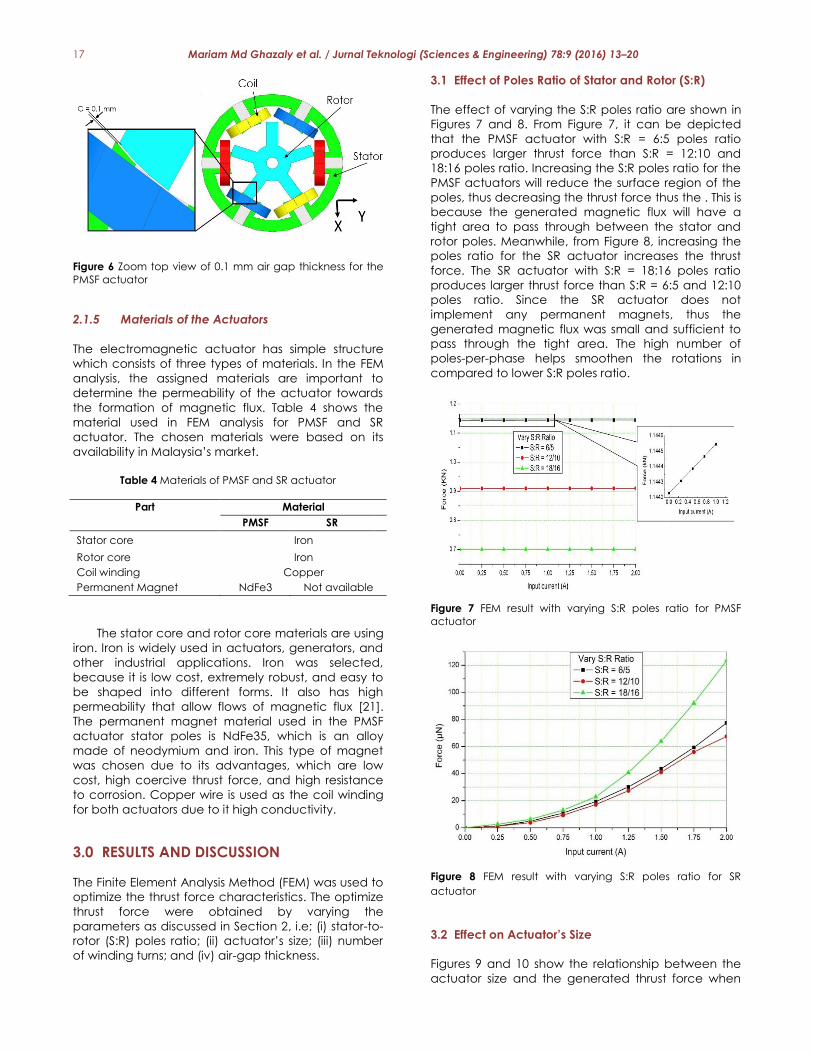
3.1 Effect of Poles Ratio of Stator and Rotor (S:R)
The effect of varying the S:R poles ratio are shown in
Figures 7 and 8. From Figure 7, it can be depicted
that the PMSF actuator with S:R = 6:5 poles ratio
produces larger thrust force than S:R = 12:10 and
18:16 poles ratio. Increasing the S:R poles ratio for the
PMSF actuators will reduce the surface region of the
poles, thus decreasing the thrust force thus the . This is
because the generated magnetic flux will have a
tight area to pass through between the stator and
rotor poles. Meanwhile, from Figure 8, increasing the
poles ratio for the SR actuator increases the thrust
force. The SR actuator with S:R = 18:16 poles ratio
produces larger thrust force than S:R = 6:5 and 12:10
poles ratio. Since the SR actuator does not
implement any permanent magnets, thus the
generated magnetic flux was small and sufficient to
pass through the tight area. The high number of
poles-per-phase helps smoothen the rotations in
compared to lower S:R poles ratio.
Figure 7 FEM result with varying S:R poles ratio for PMSF
actuator
Figure 8 FEM result with varying S:R poles ratio for SR
actuator
3.2 Effect on Actuator’s Size
Figures 9 and 10 show the relationship between the
actuator size and the generated thrust force when
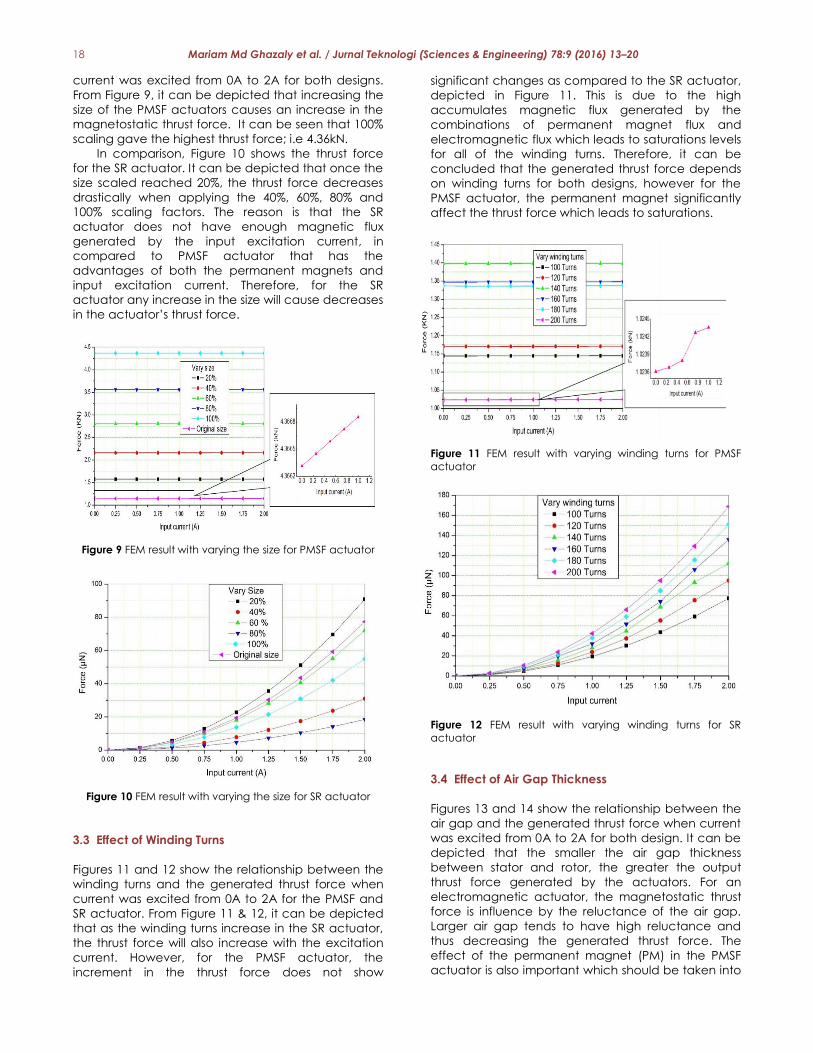
18 Mariam Md Ghazaly et al. / Jurnal Teknologi (Sciences & Engineering) 78:9 (2016) 13–20
current was excited from 0A to 2A for both designs.
From Figure 9, it can be depicted that increasing the
size of the PMSF actuators causes an increase in the
magnetostatic thrust force. It can be seen that 100%
scaling gave the highest thrust force; i.e 4.36kN.
In comparison, Figure 10 shows the thrust force
for the SR actuator. It can be depicted that once the
size scaled reached 20%, the thrust force decreases
drastically when applying the 40%, 60%, 80% and
100% scaling factors. The reason is that the SR
actuator does not have enough magnetic flux
generated by the input excitation current, in
compared to PMSF actuator that has the
advantages of both the permanent magnets and
input excitation current. Therefore, for the SR
actuator any increase in the size will cause decreases
in the actuator’s thrust force.
Figure 9 FEM result with varying the size for PMSF actuator
Figure 10 FEM result with varying the size for SR actuator
3.3 Effect of Winding Turns
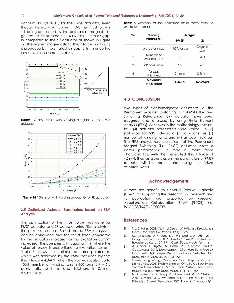
Figures 11 and 12 show the relationship between the
winding turns and the generated thrust force when
current was excited from 0A to 2A for the PMSF and
SR actuator. From Figure 11 & 12, it can be depicted
that as the winding turns increase in the SR actuator,
the thrust force will also increase with the excitation
current. However, for the PMSF actuator, the
increment in the thrust force does not show
significant changes as compared to the SR actuator,
depicted in Figure 11. This is due to the high
accumulates magnetic flux generated by the
combinations of permanent magnet flux and
electromagnetic flux which leads to saturations levels
for all of the winding turns. Therefore, it can be
concluded that the generated thrust force depends
on winding turns for both designs, however for the
PMSF actuator, the permanent magnet significantly
affect the thrust force which leads to saturations.
Figure 11 FEM result with varying winding turns for PMSF
actuator
Figure 12 FEM result with varying winding turns for SR
actuator
3.4 Effect of Air Gap Thickness
Figures 13 and 14 show the relationship between the
air gap and the generated thrust force when current
was excited from 0A to 2A for both design. It can be
depicted that the smaller the air gap thickness
between stator and rotor, the greater the output
thrust force generated by the actuators. For an
electromagnetic actuator, the magnetostatic thrust
force is influence by the reluctance of the air gap.
Larger air gap tends to have high reluctance and
thus decreasing the generated thrust force. The
effect of the permanent magnet (PM) in the PMSF
actuator is also important which should be taken into
19 Mariam Md Ghazaly et al. / Jurnal Teknologi (Sciences & Engineering) 78:9 (2016) 13–20
account. In Figure 13, for the PMSF actuator, even
though the excitation current is 0A, the thrust force is
still being generated by the permanent magnet; i.e.
generated thrust force is 1.14 kN for 0.1 mm air gap.
In compared to the SR actuator as shown in Figure
14, the highest magnetostatic thrust force (77.35 μN)
is produced by the smallest air gap, 0.1mm once the
input excitation current is at 2A.
Figure 13 FEM result with varying air gap, G for PMSF
actuator
Figure 14 FEM result with varying air gap, G for SR actuator
3.5 Optimized Actuator Parameters Based on FEM
Analysis
The optimization of the thrust force was done for
PMSF actuator and SR actuator using FEM analysis in
the previous sections. Based on the FEM analysis, it
can be concluded that the thrust force generated
by the actuators increases as the excitation current
increased. This complies with Equation (1), where the
value of torque is proportional to excitation current.
Table 5 shows the optimize actuator parameters
which was achieved by the PMSF actuator (highest
thrust force = 4.36kN) when the size was scaled up to
100%; number of winding turns is 100 turns; S:R = 6:5
poles ratio and air gap thickness is 0.1mm,
respectively.
Table 5 Summary of the optimized thrust force, with 2A
excitation current
No. Varying
Parameter
Designs
PMSF SR
1 Actuator’s size 100% larger Original
size
2 Number of
winding turns 100 200
3 S:R poles ratio 6:5 6:5
4 Air gap
thickness 0.1mm 0.1mm
Maximum
thrust force 4.36kN 168.85µN
4.0 CONCLUSION
Two types of electromagnetic actuators; i.e. the
Permanent Magnet Switching Flux (PMSF) flux and
Switching Reluctance (SR) actuator have been
designed and analyzed by using Finite Element
Analysis (FEM). As shown in the methodology section,
four (4) actuator parameters were varied; i.e. (i)
stator-to-rotor (S:R) poles ratio; (ii) actuator’s size; (iii)
number of winding turns; and (iv) air-gap thickness.
The FEM analysis results clarifies that the Permanent
Magnet Switching Flux (PMSF) actuator shows a
better performances in term of thrust force
characteristics, with the generated thrust force of
4.36kN. Thus, as a conclusion, the parameters of PMSF
actuator will be the selected design for future
research works.
Acknowledgement
Authors are grateful to Universiti Teknikal Malaysia
(UTeM) for supporting the research. This research and
its publication are supported by Research
Acculturation Collaboration Effort (RACE) no.
RACE/F3/TK5/FKE/F00249.
References [1] T. J. E. Miller. 2002. Optimal Design of Switched Reluctance
Motors. Industrial Electronics. 49(1): 15-27.
[2] M. Tanujaya, D.-H. Lee, Y.-J. An, and J.-W. Ahn. 2011.
Design And Analysis Of A Novel 4/5 Two-Phase Switched
Reluctance Motor. 2011 Int. Conf. Electr. Mach. Syst. 1-6.
[3] A. Chiba, K. Kiyota, N. Hoshi, M. Takemoto, and S.
Ogasawara. 2015. Development Of A Rare-Earth-Free SR
Motor With High Torque Density For Hybrid Vehicles. IEEE
Trans. Energy Convers. 30(1): 5-182.
[4] Shuanghong Wang, Qionghua Zhan, Zhiyuan Ma, and
Libing Zhou. 2005. Implementation Of A 50-Kw Four-Phase
Switched Reluctance Motor Drive System For Hybrid
Electric Vehicle. IEEE Trans. Magn. 41(1): 501-504.
[5] N. Schofield, S. A. Long, D. Howe, and M. McClelland.
2009. Design Of A Switched Reluctance Machine For
Extended Speed Operation. IEEE Trans. Ind. Appl. 45(1):

20 Mariam Md Ghazaly et al. / Jurnal Teknologi (Sciences & Engineering) 78:9 (2016) 13–20
116-122.
[6] Z. Q. Zhu and J. T. Chen. 2010. Advanced Flux-Switching
Permanent Magnet Brushless Machines. IEEE Trans. Magn.
46(6): 1447-1453.
[7] W. Z. Fei and J. X. Shen. 2006. Comparative Study And
Optimal Design Of PM Switching Flux Motors. 41st Int. Univ.
Power Eng. Conf. UPEC 2006, Conf. Procedings. 2: 695-699.
[8] M. Takeno, S. S. Member, Y. Takano, A. Chiba, N. Hoshi, M.
Takemoto, S. Ogasawara, and T. Imakawa. 2011. Torque
Density and Efficiency Improvements of a Switched
Reluctance Motor Without Rare-Earth Material for Hybrid
Vehicles. IEEE Trans. Ind. Appl. 47(3): 1240-1246.
[9] Yamazaki, K. 2003. Torque And Efficiency Calculation Of
An Interior Permanent Magnet Motor Considering
Harmonic Iron Losses Of Both The Stator And Rotor. IEEE
Transactions on Magnetics. 39(3): 1460-1463.
[10] P. T. Hieu, D. Lee, and J. Ahn. 2015. High Speed 2-Phase 4 / 3 Switched Reluctance Motor for Air-blower Application :
Design, Analysis, and Experimental Verification. 2015 18th
Int. Conf. Electr. Mach. Syst. 4-8.
[11] H. Hayashi, K. Nakamura, A. Chiba, T. Fukao, K.
Tungpimolrut, and D. G. Dorrell. Efficiency Improvements
Of Switched Reluctance Motors With High-Quality Iron
Steel And Enhanced Conductor Slot Fill. IEEE Trans. Energy
Convers. 24(4): 819-825.
[12] K. Lu, P. O. Rasmussen, S. J. Watkins, and F. Blaabjerg.
2011. A New Low-Cost Hybrid Switched Reluctance Motor
for Adjustable-Speed Pump Applications. IEEE Trans. Ind.
Appl. 47(1): 314-321.
[13] Q. Zhou, C. Liu, W. Zeng, and D. Liu. 2008. Maximization of
Starting Torque of a Three-phase 6/2 Switched Reluctance
Motor for Super High Speed Drive. Int. Con. on Electrical
Machines and Systems. 60(1): 3385-3388.
[14] X. Liu and Z. Q. Zhu. 2013. Electromagnetic Performance
Of Novel Variable Flux Reluctance Machines With DC-
Field Coil In Stator. IEEE Trans. Magn. 49(6): 3020-3028.
[15] B. Bilgin, A. Emadi, and M. Krishnamurthy. 2012. Design
Considerations For Switched Reluctance Machines With A
Higher Number Of Rotor Poles. IEEE Trans. Ind. Electron.
59(10): 3745-3756.
[16] J. T. Shi, X. Liu, D. Wu, and Z. Q. Zhu. 2014. Influence Of
Stator And Rotor Pole Arcs On Electromagnetic Torque Of
Variable Flux Reluctance Machines. IEEE Trans. Magn.
50(11).
[17] M. M. Ghazaly, K. Sato, A. C. Amran, and A. C. Tan. 2015.
Force Characterization of a Rotary Motion Electrostatic
Actuator Based on Finite Element Method (FEM) Analysis.
Appl. Mech. Mater. 761: 233-237.
[18] M. M. Ghazaly, T. K. Lim, Y. P. Chin, and K. Sato. Force
Optimization of An Force Artificial Muscle Actuated
Underwater Probe System Using Linear Motion
Electrostatic Motor. J. Teknol. 74(9): 191-196.
[19] M. Takeno, A. Chiba, N. Hoshi, S. Ogasawara, M.
Takemoto, and M. A. Rahman. Test Results And Torque
Improvement Of The 50-Kw Switched Reluctance Motor
Designed For Hybrid Electric Vehicles. IEEE Trans. Ind. Appl.
48(4): 1327-1334.
[20] K. A. Danapalasingam. 2007. Energy Optimization Of
Brushed DC Motor In Electric Power-Assisted Steering. J.
Teknol. 3(3): 63-67.
[21] V. Vivek, S. Prachi, and S. Adarsh. 2014. Effect Of Iron
Content On Permeability And Power Loss Characteristics
of Li0⋅35Cd0⋅3Fe2⋅35O4 and Li0⋅35Zn0⋅3Fe2⋅35O4. Bull.
Mater. Sci. 37(4): 855-859.