hyl ing
TRANSCRIPT
8/3/2019 hyl ing
http://slidepdf.com/reader/full/hyl-ing 1/15
HYL III: Status
And Trends
by
Raúl Quintero, President
HYL Technology Division,
Hylsa, S.A. de C.V.
presented at the
Gorham/Intertech Conference onIron & Steel Scrap, Scrap Substitutes and Direct Steel Making
Atlanta, Georgia
March 21-23, 1995
HYL Te chn ology D iv is ion H y ls a, S .A. de C .V. A v e. M un ich 1 01 66 452 S an N ic o lás de los G a rz a, N .L. M éx ic o

8/3/2019 hyl ing
http://slidepdf.com/reader/full/hyl-ing 2/15
H YL III: S ta tus and T rends (3 /95 ) 2
Introduction
HYL III technology is characterized by its wide flexibility for adapting to specialneeds, depending on available reducing gases, energy use and meltshoprequirements. Use of spent gases from direct ironmaking processes, coalgasification, energy optimization in DR plants and technology developmentsaimed to improve EAF productivity have been the objective of HYL R&D andengineering efforts over the past years.
One of the newest trends in steelmaking is the application of direct ironmakingtechnologies for production of molten iron and steel. These technologies arebased on the direct use of non-treated, non-coking coal as a reducing agent.Among these technologies, most of which are currently at various stages of
development and industrial application, such as AISI, DIOS, etc., the Corexprocess is presently working at industrial scale.
However, due to the low level of post-combustion taking place in the melter gasifier, a significant amount of energy, as spent gas, has to be released from theprocess. This export energy is so high that if no further and adequate use isconsidered, the ironmaking process itself is no longer economically feasible.Among the various options for use of the export energy (i.e., power generation,heating, synthesis gas generation, direct reduced iron production), the mosteconomically attractive application is hot DRI production.
In this regard, the direct reduction (DR) technology which best complies with therequirements of spent gas treatment and heating as well as direct feed of hot DRIfrom DR facilities to EAF/BOF, is the HYL III DR process. Feasibility of the HYL IIIprocess scheme, based on the use of Corex off-gas and gases from coalgasification, has been confirmed during recent tests being carried out in the HYLdemonstration plant.
To improve the competitiveness of the DR-EAF route in the steelmaking industry,HYL has developed technological improvements oriented to minimizing theoverall energy consumption of the DR-EAF processes. In the DR plant the targethas been achieved by energy optimization through the zero kWh scheme. In the
EAF, reduction of power requirements and productivity increase can be obtainedby the HYTEMP® iron and high carbon DRI.
8/3/2019 hyl ing
http://slidepdf.com/reader/full/hyl-ing 3/15
H YL III: S ta tus and T rends (3 /95 ) 3
HYL III Direct Reduction Process
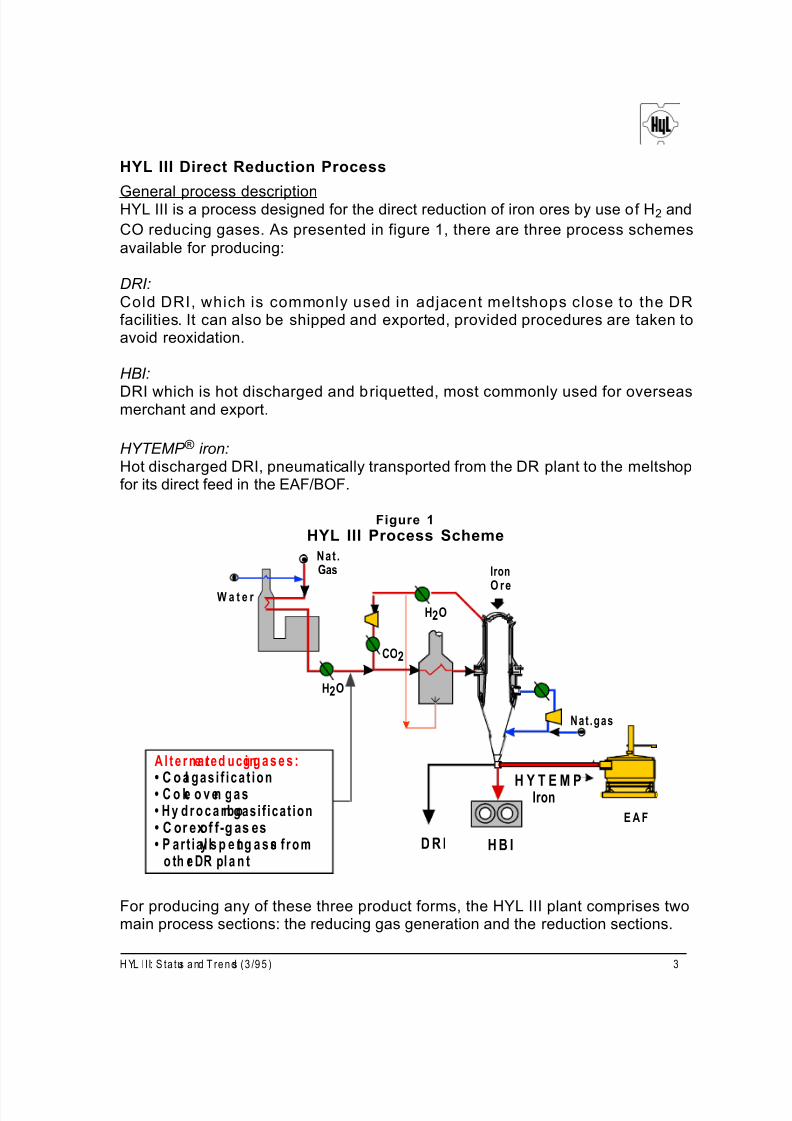
General process descriptionHYL III is a process designed for the direct reduction of iron ores by use of H2 and
CO reducing gases. As presented in figure 1, there are three process schemesavailable for producing:
DRI:Cold DRI, which is commonly used in adjacent meltshops close to the DRfacilities. It can also be shipped and exported, provided procedures are taken toavoid reoxidation.
HBI:
DRI which is hot discharged and briquetted, most commonly used for overseasmerchant and export.
HYTEMP ® iron:Hot discharged DRI, pneumatically transported from the DR plant to the meltshopfor its direct feed in the EAF/BOF.
Figure 1
HYL III Process Scheme
Nat .
W a t e r
Gas
H2O
Iron
O re
CO2
H2O
Nat .gas
A l t e r n a te red uc ing g a s e s :• C o al gas i f i ca t ion• C o ke o v en ga s• H y d r o c a r b on gasi f icat ion• C or exof f-g as es• P ar t ia l ly s p e nt g a s es f rom
o th er DR pl a n tD R I H B I
H Y T E M PIron
E A F
For producing any of these three product forms, the HYL III plant comprises twomain process sections: the reducing gas generation and the reduction sections.

8/3/2019 hyl ing
http://slidepdf.com/reader/full/hyl-ing 4/15
Both sections are independent from an operational point of view. This featureoffers important flexibility for adapting to different reducing gas sources. Typically,the reducing gas generation section consists of a conventional natural gas-steamreformer to produce the H2 + CO required as make-up for the reduction process.
However, alternate sources of reducing gases can be used instead of reformedgas. Among these are:
- Gases from coal gasification processes- Coke oven gas- Gases from hydrocarbon gasification- Partially spent gases from another DR plant
- Corex off-gases
The reduction section consists of the DR reactor, the reduction circuit and, for theparticular case of the production of cold DRI, the cooling circuit. Reducing gasesare made-up of a mixture of make-up and recycling gases. The basic componentsof the reduction circuit, aside from the reactor, are: a gas heater to increase thereducing gases temperature up to 925°C; a scrubbing unit for dedusting, coolingand H2O elimination from top gases; the recycle gas compressor and the CO2
removal unit. Here CO2 is selectively eliminated from the system for a more
efficient reuse of the recycle gas.
Use of Corex off-gas
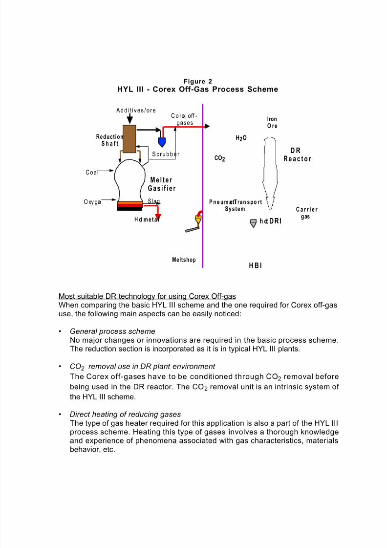
HYL III - Corex Off-gas process schemeAs presented in figure 2, the Corex off-gas is mixed with the reducing recycle gasand the combined gases stream is passed through a CO2 removal unit to
adequate the gas composit ion for the reduct ion process. The part ial l ydecarbonated gas is preheated in a direct gas heater and fed to the reactor. After reduction of iron ores in the DR reactor, top exhaust gas is passed through ascrubbing unit for dust removal and cooling. The gas is then recycled to the CO2
removal unit by the compressor.
In the case of hot product discharge, there is the flexibility to obtain part of theproduct as HBI and to send hot DRI pneumatical ly to the meltshop by the
HYTEMP® System, simultaneously.
Specific requirements of Corex off-gas per tonne (t) of DRI depend basically first,on the N2 content and secondly on the process selected for CO2 removal. The
higher the amount of gases purged from the DR plant, the higher the specificCorex off- gas make-up required.
8/3/2019 hyl ing
http://slidepdf.com/reader/full/hyl-ing 5/15
Figure 2
HYL III - Corex Off-Gas Process Scheme
A d d i t i v e s / o r e
ReductionS h a f t
C o rex off -gases
S c r u b b e r CO2
H2O
IronO re
D RR e a c t o r
Coa l
M e l t e r
G a s i f i e r O xy gen Slag
H ot m e t a l
P n e u m a t ic T ran spo rtSystem
h ot DRI
C a r r i e r gas
MeltshopH B I
Most suitable DR technology for using Corex Off-gasWhen comparing the basic HYL III scheme and the one required for Corex off-gasuse, the following main aspects can be easily noticed:
• General process schemeNo major changes or innovations are required in the basic process scheme.The reduction section is incorporated as it is in typical HYL III plants.
• CO2 removal use in DR plant environment
The Corex off-gases have to be conditioned through CO2 removal before
being used in the DR reactor. The CO2 removal unit is an intrinsic system of the HYL III scheme.
• Direct heating of reducing gasesThe type of gas heater required for this application is also a part of the HYL IIIprocess scheme. Heating this type of gases involves a thorough knowledgeand experience of phenomena associated with gas characteristics, materialsbehavior, etc.

8/3/2019 hyl ing
http://slidepdf.com/reader/full/hyl-ing 6/15
• HYTEMP ® iron use
Potential incorporation of the HYTEMP®
System for use of hot DRI to theEAF/BOF leads to important economic benefits related to improvements of
DRI/hot metal ratio, power savings and productivity increase. HYTEMP® ironpresents a unique option as an additional product for the Corex off-gas / HYLIII scheme.
• High operating pressureThe high operating pressure of the HYL III process -about 5 bars- is animportant parameter for this particular application. Since CO2 partial pressure
(CO2 concentration x gas pressure) is the driving force for CO2 removal,
elimination efficiency of CO2 is improved by the high operating pressure of the
HYL III process.
By properly selecting the CO2 removal system, reducing gas heating and proper
energy use, an overall optimized process scheme can be achieved, in terms of both:
- plant productivity and- energy consumption
Thus, it is possible to optimize the use of Corex off-gas in the HYL III process
since:
- There is no surplus gas to be exported from the DR plant -for N2 < 4%.
All tail gas is used as fuel in the gas heater.
- All thermal energy requirements for CO2 removal (via steam) are
covered in- plant by taking advantage of process waste energy.
- A totally energy-balanced scheme is achieved while maximizing theamount of DRI being produced from available Corex spent gas.
These figures, presented in table 1 are based on a typical HYTEMP ® iron of 92%metallization and carbon of 0.8%, being discharged at 700°C.

8/3/2019 hyl ing
http://slidepdf.com/reader/full/hyl-ing 7/15
Table 1
DR Plant Productivity and Consumption Figures
Item
Productivity:
unit/tonne DRI
1.2 ton DRI/ton HM
Remarks
as minimum
Corex off-gas: 1250 Nm3 ( ~2.35 gcal) depends on the N2 concentration
Electricity: 170 kWh depends on the CO2 removal system
Water makeup: 1.4 m3 depends on the CO2 removal system
Steam: 0 ton depends on the CO2 removal system
Labor: 0.25 m-h (steam req’d ~ 0.35 is generated in-plant)
Maintenance: $US3.50
Energy optimization in the HYL III process
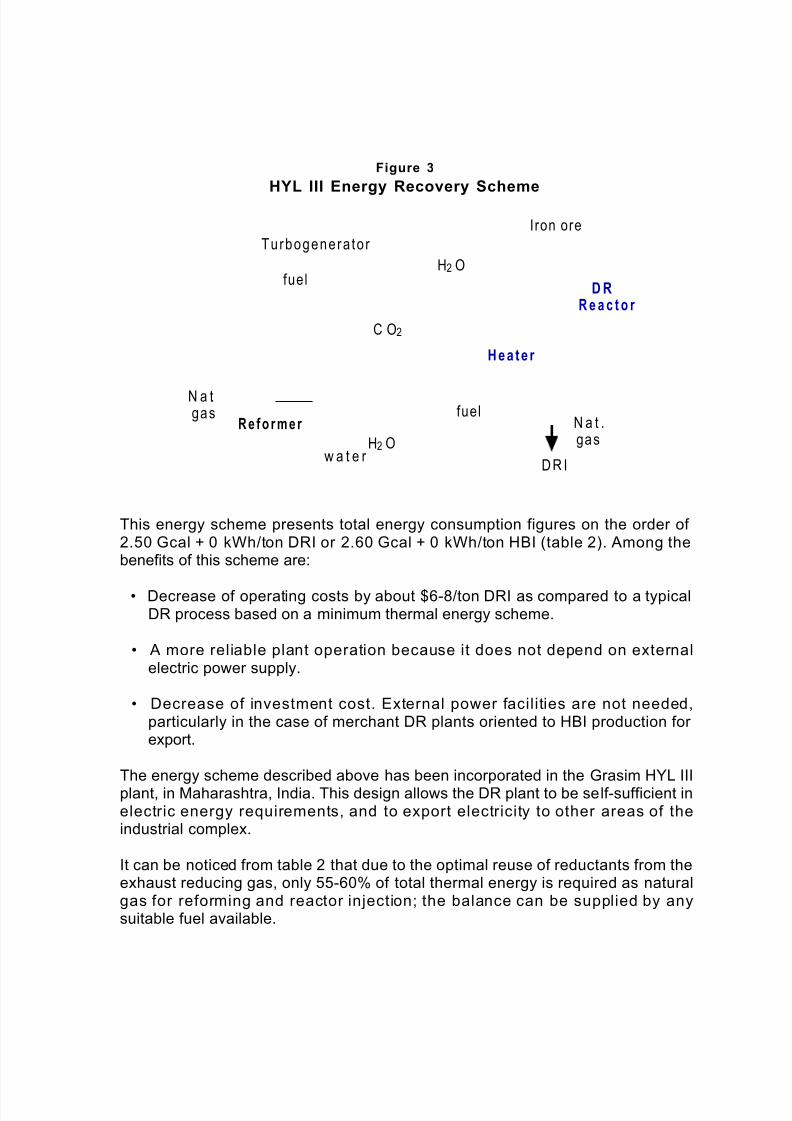
As shown in figure 3, in the typical HYL III process scheme the sensible heat of hot reformed gas and flue gases from the reformer is used mainly for steamgeneration. Steam requirements for the plant are for two end-users: steam for reforming and exhaust steam for the CO2 absorption system in the reduction
circuit.
The amount and pressure of the steam produced have been specified in order toattain an optimum thermal and mechanical balance of the plant. In the improved
energy scheme, the steam is produced at high pressure (63 kg/cm2 A), in order totake maximum advantage of the steam enthalpy for electricity generation in asingle high-efficiency turbogenerator, before being used for reforming and in theCO2 stripper reboiler. In this way the total electric power requirements can be
generated in-plant without depending on external power sources.
The capacity of the turbogenerator is about 90 kWh/ton DRI for cold discharge or 105 kWh/ton HBI for hot discharge, sufficient to comply with the total electricityneeds of the plant.
This self-sufficient electric power scheme, without the need for additionalequipment or major modifications to the plant, is exclusive to the HYL III process. Itoffers important advantages related to reductions of investment and operatingcosts, and improvements in plant availability, particularly in areas where thereliability of electricity supply is low.
8/3/2019 hyl ing
http://slidepdf.com/reader/full/hyl-ing 8/15
Figure 3
HYL III Energy Recovery Scheme
Turbogenera to r
fuel
C O2
H2 O
He a t e r
I ron ore
D RR e a c t o r
N a t.gas
R e f o r m e r
w a t e r H2 O
fuel
D R I
N a t .gas
This energy scheme presents total energy consumption figures on the order of 2.50 Gcal + 0 kWh/ton DRI or 2.60 Gcal + 0 kWh/ton HBI (table 2). Among thebenefits of this scheme are:
• Decrease of operating costs by about $6-8/ton DRI as compared to a typicalDR process based on a minimum thermal energy scheme.
• A more reliable plant operation because it does not depend on externalelectric power supply.
• Decrease of investment cost. External power facilities are not needed,particularly in the case of merchant DR plants oriented to HBI production for export.
The energy scheme described above has been incorporated in the Grasim HYL IIIplant, in Maharashtra, India. This design allows the DR plant to be self-sufficient inelectric energy requirements, and to export electricity to other areas of theindustrial complex.
It can be noticed from table 2 that due to the optimal reuse of reductants from theexhaust reducing gas, only 55-60% of total thermal energy is required as naturalgas for reforming and reactor injection; the balance can be supplied by anysuitable fuel available.

8/3/2019 hyl ing
http://slidepdf.com/reader/full/hyl-ing 9/15
Table 2
Expected Energy Consumption of the HYL III DR PlantSelf-sufficient Electric Power Scheme
1. Thermal Energy (Gcal/ton)• Natural Gas
DRI HBI
- Reforming 1.02 1.17- Reactor Injection 0.33 0.33
Total natural gas 1.35 1.50• Fuel 1.13 1.06Total Thermal Energy 2.48 2.56
2. Electric Energy (kWh/ton) 0 0
HYT EM P® iron and high-carbon DRI
HYTEM P® system description
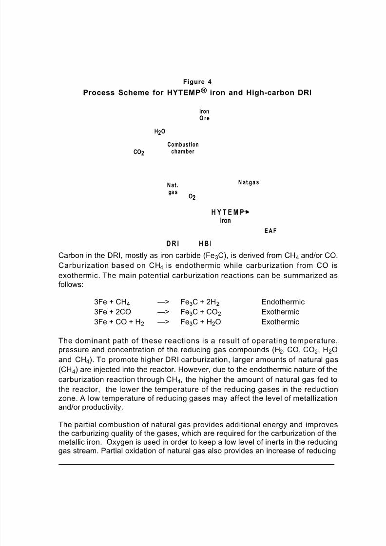
Hot DRI, or HYTEMP® iron, discharged at temperatures ranging from 650° to700°C, with metallization up to 95% and controlled carbon of 1.2 to > 4.0%, is feddirectly to the pneumatic transport system and sent to the EAF feeding bins in themeltshop. In this way, the DRI’s heat is capitalized on in the EAF.
As presented in figure 4, the DR plant is designed for hot discharge of DRI.According to the particular requirements of steelmaking installations, an off-linedischarge for DRI cooling can be used when the EAF is not in operation, or abriquetting machine can be installed if part of the production is being sent for export.
The hot DRI is discharged from the rotary valve directly to the pneumatic transportpiping loop. Transport is carried out at the same rate as the DR reactor productionrate. Process gas or inert gas is utilized as transport gas make-up, at the samepressure and similar temperature as prevails at the DR reactor discharge.
Process description for high-carbon DRICombustion chambers at the reactor inlet in HYL I (fixed bed) process basedplants have historically been utilized to boost the reducing gas temperaturecoming from low temperature heaters. Partial combustion made it possible toovercome the old heaters’ constraints for achieving reduction temperatures above900°C. This concept has recently been incorporated in the HYL III processscheme to attain high carbon content in the DRI. Normal figures of carbon contentin the HYL III DRI range from 1.2 up to 2.4%. To obtain carbon levels above 2.4%and up to >4.0%, there is a modified process scheme, which is shown in figure 4.
8/3/2019 hyl ing
http://slidepdf.com/reader/full/hyl-ing 10/15
Figure 4
Process Scheme for HYTEMP ®
iron and High-carbon DRI
CO2
H2O
Combustionchamber
IronO re
Nat .
ga s O2
N at .ga s
D R I H B I
H Y T E M PIron
E A F
Carbon in the DRI, mostly as iron carbide (Fe3C), is derived from CH4 and/or CO.
Carburization based on CH4 is endothermic while carburization from CO is
exothermic. The main potential carburization reactions can be summarized as
follows:
3Fe + CH4 —> Fe3C + 2H2 Endothermic
3Fe + 2CO —> Fe3C + CO2 Exothermic
3Fe + CO + H2 —> Fe3C + H2O Exothermic
The dominant path of these reactions is a result of operating temperature,pressure and concentration of the reducing gas compounds (H2, CO, CO2, H2O
and CH4). To promote higher DRI carburization, larger amounts of natural gas
(CH4) are injected into the reactor. However, due to the endothermic nature of the
carburization reaction through CH4, the higher the amount of natural gas fed tothe reactor, the lower the temperature of the reducing gases in the reductionzone. A low temperature of reducing gases may affect the level of metallizationand/or productivity.
The partial combustion of natural gas provides additional energy and improvesthe carburizing quality of the gases, which are required for the carburization of themetallic iron. Oxygen is used in order to keep a low level of inerts in the reducinggas stream. Partial oxidation of natural gas also provides an increase of reducing
8/3/2019 hyl ing
http://slidepdf.com/reader/full/hyl-ing 11/15
gases for reduction (as CO and H2). Since a significant amount of natural gas is
injected directly to the reactor, the reformed gas make-up for this case is lower when compared to a typical process scheme.This process scheme can be adapted to DR plants designed for either cold andhot DRI production with no adverse effect on plant productivity. Typical analysis of normal and h igh carbon DRI , obta ined f rom h igh quali ty i ron ores, aresummarized in table 3.
Table 3
Typical DRI characteristics
Typical DRI High carbon DRI
Item (% weight) (% weight)Metallization 94.00 94.00Total iron 93.14 91.05Metallic iron 87.56 85.59FeO 7.18 7.03Carbon 1.80 4.00Gangue 3.46 3.38
Fe3C 25.59 55.66
The high-carbon cold DRI is stable enough to be transported inland safely. High-
carbon cold DRI can be produced by merchant plants supplying the product tovarious domestic EAF based mini-mills. To some extent, this product can also beused for export, mainly for regional distribution, decreasing significantly theoperating cost of merchant DR plants while producing a more valuable metalliccharge for the EAF.
Current projects under executionIn the past years, the R&D department has done extensive work at the pilot plantfacilities’ 24 tonnes per day reactor, using partial combustion of natural gas at thereactor inlet for increasing DRI carbon content.The experimental results are presently being extrapolated to industrial scale to
give the required flexibility to DR plants in order to obtain a wide range of carbonin the DRI. Since this process scheme requires lower make-up of reducing gas,additional advantages are related to increase of production for existing DRfacilities. Plants currently operating with this process scheme are:
• The Hylsa 2M5 and 3M5 DR plants in Monterrey, Mexico. Combustionchambers have been insta lled to achieve an increase of 6-8% DRIproduction with carbon content of >3%. This process scheme went intooperation at the end of Feb. 1995. Net savings in the meltshop by utilizing
8/3/2019 hyl ing
http://slidepdf.com/reader/full/hyl-ing 12/15
this “medium carbon” DRI are about $1.9 per tonne of liquid steel. Future
incorporation of the HYTEMP® system to the 3M5 plant will allow delivery of hot high-carbon DRI directly to the new meltshop, which will allow further reductions in EAF operating costs.
• Usiba DR plant in Brazil has been converted to the HYL IIIprocess.
Incorporation of the combustion chamber has allowed the plant capacity toincrease from 240 to 320,000 tonnes/year of DRI with carbon levels of about2.5%, while taking advantage of the existing low temperature heaters, thusdecreasing significantly the project capital cost. The plant started up on Dec.25 and the performance test was successfully achieved at the beginning of
Feb. 1995.
Overall b enefits of high-carbon and HYTEM P® iron in theEAFThe combined effects of high temperature and high carbon content of DRI have apositive influence on the productivity of the EAF, arising from the correspondingdecrease of the electric energy required to melt the charge.
The sensible heat of the DRI results in a lower electric energy consumption in thefurnace, increasing productivity and reducing related operating costs, such aselectrodes, refractories and fluxes.
Additionally, the high carbon content (mostly as iron carbide) plays a significantrole in providing energy to the system in a clean and easy manner, withoutgraphite additions to the bath. This also allows the use of increased amounts of oxygen, which has the positive effect of increasing productivity.
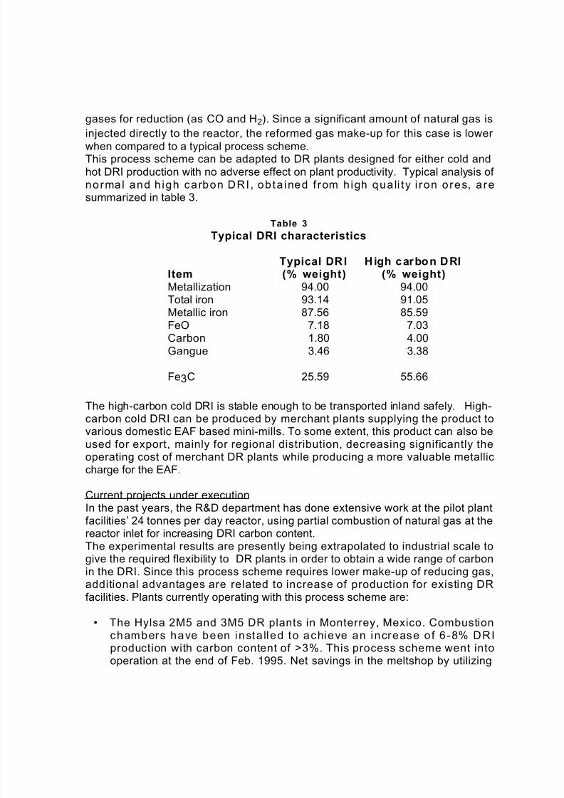
The amount of oxygen consumption in the EAF using different charges of DRI atvarious carbon levels is presented in figure 5. This information is used as basis for the estimation of electricity consumption and productivity in the EAF.
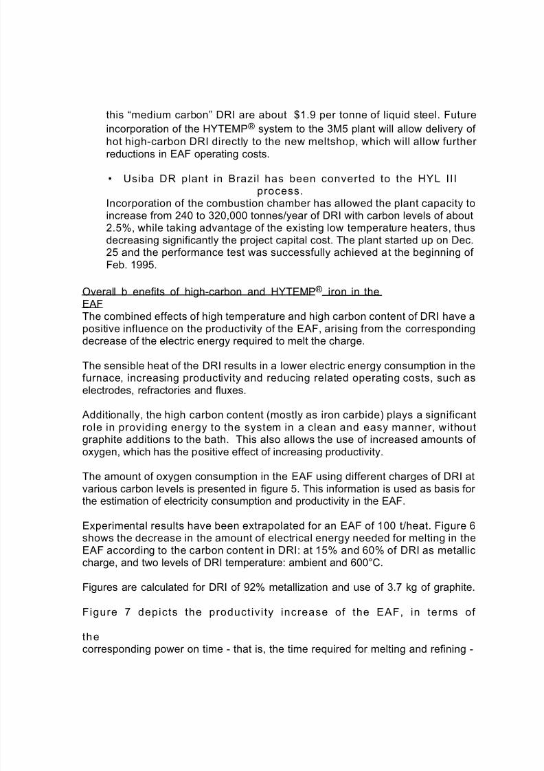
Experimental results have been extrapolated for an EAF of 100 t/heat. Figure 6
shows the decrease in the amount of electrical energy needed for melting in theEAF according to the carbon content in DRI: at 15% and 60% of DRI as metalliccharge, and two levels of DRI temperature: ambient and 600°C.
Figures are calculated for DRI of 92% metallization and use of 3.7 kg of graphite.
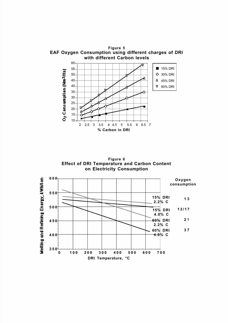
Figure 7 depicts the product ivi ty increase of the EAF, in terms of
thecorresponding power on time - that is, the time required for melting and refining -

8/3/2019 hyl ing
http://slidepdf.com/reader/full/hyl-ing 13/15
depending on DRI temperature, DRI carbon and metallic charge composition.
8/3/2019 hyl ing
http://slidepdf.com/reader/full/hyl-ing 14/15
Figure 5
EAF Oxygen Consumption using different charges of DRI
with different Carbon levels60
55
50
45
40
35
30
25
20
15
10
2 2.5 3 3.5 4 4.5 5 5.5 6 6.5 7
% Carbon in DRI
15% DRI
30% DRI
45% DRI
60% DRI
Figure 6
Effect of DRI Temperature and Carbon Content
on Electricity Consumption
6 0 0 Oxygen
consumption
5 5 0
5 0 0
4 5 0
4 0 0
3 5 0
15% DRI
2.2% C
15% DRI
4.0% C
60% DRI
2.2% C60% DRI
4.0% C
0 1 0 0 2 0 0 3 0 0 4 0 0 5 0 0 6 0 0 7 0 0
DRI Temperature, °C
1 3
1 3 / 1 7
2 1
3 7

8/3/2019 hyl ing
http://slidepdf.com/reader/full/hyl-ing 15/15
Figure 7
Effect of Temperature and Carbon on Melting and Refining Time
9 0
8 5
8 0
15% DRI7 5
2.2% C
15% DRI7 0
4.0% C
6 5 60% DRI
2.2% C
6 0 60% DRI
4.0% C5 5
5 00 1 0 0 2 0 0 3 0 0 4 0 0 5 0 0 6 0 0 7 0 0
Temperature, °C
Conclusions
When combined with Corex off-gas as a source of reducing gas, the HYL III DRplant offers high productivity using available spent gas, and benefits in steel
production by using HYTEMP® iron together with hot metal in EAF/BOF basedsteel mills.
The HYL III plant scheme allows zero electric power consumption with totalthermal energy requirements of about 2.50 Gcal/ton of product. This has beenachieved by the efficient utilization of the steam required for final users, with theadequate specification of the steam thermodynamic path. This scheme presentsadvantages in terms of the DR plant investment and operating costs, and offers aunique position for DR plants to be located far from electric power distributionfacilities.
Carbon levels ranging from 1.2 to >4.0% can be achieved in the HYL III process
for both DRI or hot DRI (HYTEMP® iron). Benefits of this process scheme arerelated to important improvements of EAF operating costs and productivity.
HYTEMP® iron and high carbon DRI (mostly as iron carbide) play a significantrole in providing energy to the EAF by decreasing electricity consumption andallowing utilization of oxygen, thus leading to the positive effect of increasedproductivity.
• • •