iiieprints.utem.edu.my/9538/1/smart_automatic_dual_function_lawn... · manfaat dari sistem seperti...
TRANSCRIPT

iii
“I hereby declare that this report is the result of my own work except for quotes as
cited in the references.”
Signature : ……………………….
Author : ABDUL HALIM BIN MUSTAFA
Date : ………………………..

iv
“I hereby declare that I have read this report and in my opinion this report is
sufficient in term of the scope and quality for the award of bachelor of Electronic
Engineering (Industrial Electronics) With Honours.”
Signature : ………………………
Supervisor’s Name : ENGR. Mohd Muzafar bin Ismail
Date : ………………………

v
I dedicate to my family especially my mother who always supporting me. Also
always beside me are brothers, my nephews, lectures and all my friends.

vi
ACKNOWLEDGEMENT
Alhamdulillah, all praise to Allah the Most Beneficent and the Most Merciful, who
has taught what I knew not. It is the grace of the Almighty Allah that this research
work has been completed successfully on time.
First and foremost, I would like to take this opportunity to thank my project
supervisor, ENGR. Mohd Muzafar bin Ismail for this invaluable guidance, assistance
and support throughout the project. Under her supervision, many aspects regarding
on this project has been explored and with the knowledge, idea and support received
from him, this thesis can be presented in the time given. For all lecturer involved in
teaching my course, thanks for the lesson that been delivered.
I also would like to thank my beloved family for your support and
encouragement that you have given in my life. Also thank you for understanding me
that been given to me in completing this work. Not forget to all my friends, course
mate and anyone that has provided whether an idea or support directly or indirectly
that played a role towards in completing this work. Unfortunately, it is not possible
to list all of them in this limited space. Also special thanks to UTeM for giving me an
opportunity to pursue my course of study. Also for FKEKK that has given not only
knowledge, but also experiences during my study here.

vii
ABSTRACT
This project presents a review of researches done on the subject of automated
lawnmower. An autonomous lawnmower is a robot that can operate without or with
minimal human control, self-propelled and guided automatically along a desired
path. The benefits from such a system are useful for agriculture industry by reducing
labor cost and time, as well as improving output efficiency by eliminating human
errors. Many researches and inventions have been made, with the results ranging
from successful, encouraging to some that are impractical for commercial
implementation for certain reasons. These implements include sensor, machine
vision, ultrasonic transmitter and as well as actuator and servo motor.
In committed situations, robots can do and should do the job for us. Robots
are not only used in outer space, but, there are many places on earth where it is too
dangerous for man to work at like in the deep sea, nuclear plants or waste dumps.
Hence, there is also a growing need for robots in supporting human beings in their
daily life at home or at work [18]. These are also reasons for the limited workforce
available in this sector. The operation of a lawn is a skill and labor intensive task and
furthermore the shortage and aging workforce in agriculture results in a decrease of
skilled machine operators. Therefore, the development of driverless lawn tractor is of
commercial significance and societal importance.
viii
ABSTRAK
Projek ini membentangkan kajian kajian yang dilakukan ke atas subjek mesin
pemotong rumput automatik. Mesin pemotong rumput automatik adalah robot yang
boleh beroperasi tanpa atau dengan kawalan minimum manusia, yg maju bergerak
sendiri dan dibimbing secara automatik di sepanjang jalan yang dikehendaki.
Manfaat dari sistem seperti itu adalah berguna untuk industri pertanian dengan
mengurangkan kos buruh dan masa, serta meningkatkan kecekapan pengeluaran
dengan menghapuskan kesilapan manusia. Banyak penyelidikan dan ciptaan telah
dibuat, dengan keputusan yang terdiri dari berjaya, menggalakkan kepada beberapa
yang tidak praktikal untuk implementasi komersial atas sebab-sebab tertentu. Alat-
alat ini termasuk sensor, penglihatan mesin, pemancar ultrasonik dan serta penggerak
dan motor servo.Dalam situasi yang komited, robot boleh buat dan patut buat kerja
untuk kita. Robot bukan sahaja digunakan di angkasa lepas, tetapi, terdapat banyak
tempat di bumi di mana ia adalah terlalu berbahaya bagi manusia untuk bekerja di
seperti di laut dalam, loji nuklear atau tempat pembuangan sampah sisa. Oleh itu,
terdapat juga keperluan yang meningkat bagi robot dalam menyokong manusia
dalam kehidupan seharian mereka di rumah atau di [18] kerja. Ini adalah juga sebab-
sebab bagi tenaga kerja yang terhad dalam sektor ini. Operasi padang kemahiran dan
tugas buruh intensif dan tambahan pula kekurangan dan tenaga kerja penuaan dalam
hasil pertanian di penurunan mesin mahir. Oleh itu, pembangunan traktor rumput
pemandu kepentingan komersil dan kepentingan masyarakat.
ix
TABLE OF CONTENT
CHAPTER TITLE PAGE
DEDICATION i
ACKNOWLEGMENT ii
ABSTRACT vii
TABLE OF CONTENTS iv
LIST OF FIGURE xii
I INTRODUCTION 1
1.0 Overview 1
1.1 Introduction 1
1.2 Problem statement 2
1.3 Objective of project 2
1.4 Project scope 2
1.5 Significant of study 4
II LITERATURE REVIEW 5
2.0 Introduction 5
2.1 Control circuit 5
2.2 Components and equipment 6
2.2.1 Microprocessor 16F877A 6
2.2.2 Example program for PIC 16F877A 6
2.2.3 Crystal oscillator 14
2.2.3.1 Operation of Crystal oscillator 15
2.2.4 Voltage regulator 16
x
2.2.5 Infrared sensor 18
2.2.6 Metal detector 19
2.2.7 Radio frequency module 20
2.3 Review Comparison with Previous Product 21
III METHODODLOGY 22
3.0 Introduction 22
3.1 Collection Data 23
3.1.1 Proteus lite 23
3.1.2 PICkit 24
3.2 Project Planning 26
3.3 Flow Chart of the Project Implementation 27
3.3.1 Project Selection 28
3.3.2 Title Selection 28
3.3.3 Discussion with the Lecturer about the Title 28
3.3.4 Search a suitable circuit for the project 28
3.3.5 Analysis about the circuit and the component 28
3.3.6 Print the circuit on PCB 29
3.3.7 Etching Circuit 30
3.3.8 Drilling Process 31
3.3.9 Drill 31
3.3.10 Installation the component 31
3.3.11 Circuit Testing 32
3.3.12 Soldering Process 32
3.3.12.1 Equipment on Soldering Steps 33
3.4 Conclusion 34
IV FINDING DATA ANALYSIS 35
4.1 Introduction 35
4.2 Circuit operation 35

xi
4.2.1 Circuit of Infrared sensor 36
4.2.1.1 Circuit operation of IR circuit 36
4.2.2 Circuit of PIC16f877a and motor 37
4.2.2.1 Circuit Operation 38
4.2.3 Circuit of metal detector 39
4.2.4 Circuit remote control (RX),(TX) 40
4.2.4.1 Circuit operation 40
4.3 Block Diagram for Smart Grass Cutter 42
4.3.1 Operation of the machine 44
4.4 Figure for Finished Smart Grass Cutter 45
4.5 Data analysis 47
V DISCUSSION 49
5.1 Introduction 49
5.2 Discussion 50
VI CONCLUSION AND SUGGESTION 53
6.1 Introduction 53
6.2 Conclusion 53
6.3 Suggestion 54
REFERENCE
xii
LIST OF FIGURE
FIGURE TITLE
PAGE
Figure 2.1 Microprocessor 16F877A Output/Input 6
Figure 2.2 Crystal Oscillator 14
Figure 2.3 Crystal Oscillator circuit 15
Figure 2.4 Voltage regulator. 16
Figure 2.5 Voltage regulator diagram 17
Figure 2.6 Infrared sensor 18
Figure 2.7 Transmit and receive between IR 18
Figure 2.8 Metal detector circuit 19
Figure 2.9 RF transmitter module 20
Figure 2.10 RF receiver module 20
Figure 3.1 Proteus design suite software 22
Figure 3.2 Proteus software interface 24
Figure 3.3 Examples of 3D visualization. 24
Figure 3.4 PICkit 2 interface. 25
Figure 3.5 PICkit2 device 25
Figure 3.6 The Gantt chart for PSM 1 and PSM 2 26
Figure 3.7 Example circuit printed 29
Figure 3.8 Etching process 30
Figure 3.9 Drilling process on PCB board. 31
Figure 3.10 Soldering process. 33
Figure 3.11 Sucker process 34
Figure 4.1 Infrared sensor circuit 36
Figure 4.2 Connection of motor circuit to the PIC 16F877A circuit 37
Figure 4.3 Motor Driver 38
xiii
Figure 4.4 Metal detector circuit 39
Figure 4.5 Remote control (Transmitter) 40
Figure 4.6 Remote control (Receiver) 41
Figure 4.7 Block diagram for operation 42
Figure 4.8 Simulation using proteus 43
Figure 4.9 Top side views of Smart Grass Cutter 45
Figure 4.10 Circuit of Remote Control (Rx) 45
Figure 4.11 Circuit of Remote Control (Tx) 46
Figure 4.12 Circuit of IR Sensor 46
Figure 4.13 Circuit of Metal Detector 46
Figure 4.14 Circuit of Motor 47
Figure 4.15 Circuit for PIC 16F877A 47
Figure 5.1 Microchip PIC 16F877A 50
Figure 5.2 Pinout for 16F877A 51
Figure 5.3 Coding for Initialize ports as an input and output. 52
Figure 5.4 Coding for main function 52
LIST OF TABLE
Table 2.1 Comparation Microcontroller. 7
Table 2.2 PIC16f877 pin out description 8
Table 2.3 Comparison between previous products. 21
Table 4.1 Result of Data Analysis 48

xiv
LIST OF APPENDIXS
NO TITLE PAGE
A Coding 58
1
CHAPTER 1
INTRODUCTION
1.0 Overview
This chapter will explain the introduction of study and problem
statement. The problem is reducing man power in daily work. Besides, Objective
of study and scope is explained in this chapter. The previous study is listed to get
a reflective on this study.
1.1 Introduction
Nowadays, people need new invention that can save their time, easy to
use and flexible. As an addition, it will help people to make the work become
easier. So came out with this project on making a machine that requires all the
above matter.
This project is basically about grass cutter machine which name it as
‗Smart Grass Cutter‘. Thus creation can help on human to make their work
become easier because the cutting process can be done in two ways which is
automatic and manually by the machine, furthermore the consumption of using
2
fuel will be decrease because battery will be used to produce energy which will
generate the machine.
There are some basic equipment that will be used in this project which is
the battery, servo motor, sensor (metal detector, voltage indicator and IR sensor)
PIC and blade. Furthermore, a border wire is set up around the lawn that defines
him area to be moved. This machine will use the wire to locate the boundary of
to be trimmed.
1.2 Problem statement
Nowadays, Lawnmower is used to make human‘s life much easier to do lawn
mowing. As we can see today, most people still use man power on cutting grass. This
project is an invention and a way to make human life become easier which is they can
save their time. These following are the problems are occurred and the reasons why
people rarely use this smart grass cutter.
There are many design has been made in the market, each design have a
particular purpose. The small lawnmower types are suitable for small residential lawns
and garden, while larger, self-container or ride-on mowers are suitable for large lawns.
Usually, time to use to cut the lawn is longer, depending on how large the size of
the lawn. Moreover, the machine needs lots of man power to conduct so that the
machine will be in its position. With this invention that is automatic lawnmower, it just
spend about 5 minute to set up and left the machine to finish the job.
Besides that, the cost cut grass is expensive which includes the cost of hiring
people, fuel and maintenance. This invention will help in reducing this cost where it will
reduce to the maximum level. Besides that, by using the smart grass cutter there is no
need to use the fuel. No fuel means, no emission and no pollution. There is 0% of
exhaust emission on this machine. [17]
3
1.3 Objectives of Project
The objectives of this project are:
1. To make this machine in automatic and manual condition.
2. To create a machine without strict monitor.
3. To create grass cutter machine without using the fuel.
1.4 Project Scope
For this project it focuses more on domestic use. The machine is use for cutting
grass on the house lawn. It also needs a border wire as a guide for the machine to work
inside the border wire. This machine use IR detector to detect any obstacle like small
rock, object within certain distance. As an addition, metal detector also is use to detect
metal in certain distance. Last but not least, voltage indicator is use to indicate the
amount of battery left whether it need to be recharge for the machine to work.
I. Sensor
This project metal detector as a sensor. Metal detector use
electromagnetic induction to detect border wire.
IR sensor also will be used which is use to detect any obstacles that can
be found on the ground for example vase, toy car and tricycle.
II. Blades
In this cutting grass machine, cable ties as the blade because it is easy to
be replace and can get it anywhere. Furthermore it is light and has more
safely because it is not sharp when handle it during the changing the
cable.
4
III. Battery
Multiple batteries between 3V-12V in the smart grass cutter. This battery
will be used to save and generate the machine.
This battery can be recharge.
IV. Chassis
Light material which is aluminums.
It is covered by plastic cardboard.
V. Remote control
The remote control which is transmitter and receiver.
The remote control to avoid the area that the area that not spotted.
1.5 Significant of study
Lawn mowing is an important part of the process to keep terrain with grass well
manicured and tidy. Places such as soccer field, garden, home lawn, golf course and
many others require constant lawn mowing and grass cutting. One of the complicated
tasks is mowing, with large amount of time and effort needed to complete it. Depending
on geographical location and weather trends such as rainfall and temperature, it is
generally necessary to move a lawn on a weekly basis. The duration to complete the task
takes from minutes to hours, depending on the size of the particular lawn and the
moving equipment available. The required long hours and the complicated job would
make the operator to succumb to fatigue. It is a fact that humans have some physical
limitations regarding environmental factors such as weather conditions, including
temperature, pressure, humidity and so on which causes low blood pressure and poor
fluid intake. [17]

5
CHAPTER 2
LITERATURE REVIEW
2.0 Introduction
One of the objectives of this project is making the smart grass cutter operate
easily. Therefore, it is important on reviewing the literature on this project. Explaining
the theory on all related component through findings, collecting and gathering all needed
information to attain the objectives. Besides that, we can determine the important
component used in this project. The process of gathering information will help us to
understand our project much more through expert researchers who had done similar
studies in the past.
2.1 Controlling circuit
Control circuit is the most important part in this project; this is to make sure that
the project can be function well as the planned. In this project, I have chosen some
control circuit such as, Microcontroller, speed controller and infrared sensor and metal
detector. All of this control circuit are use to make sure that the circuit can operate and
perform well in future.
6
2.2 Component and equipment
Electronic components are the most important appliance in an electronic circuit.
Components or circuit findings are create and defined by performance characteristics of
a component. Components are produced with its functions and operated in accordance
with the resolution made. The components that will use in this project are the
microprocessor, resistor, capacitor, relay etc. There are also a variety of tools used such
as soldering iron, suckers, and others.
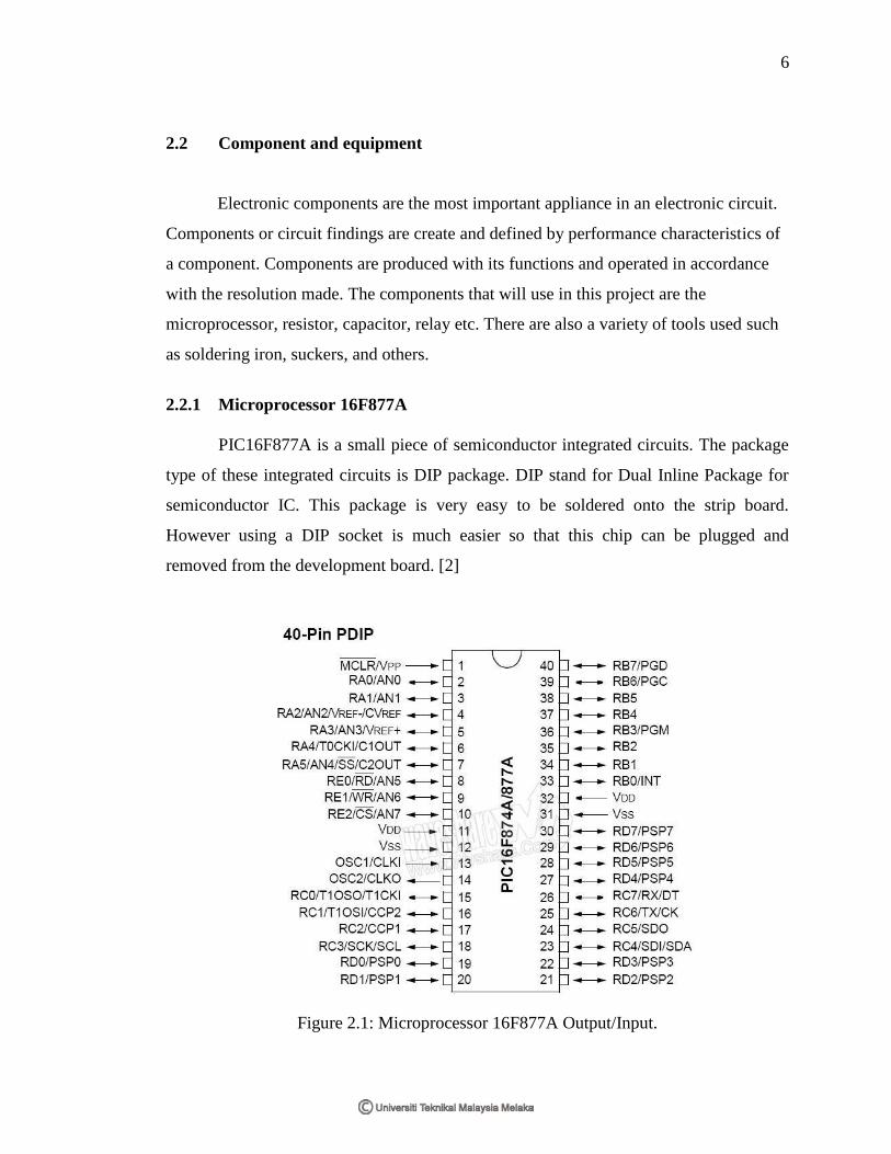
2.2.1 Microprocessor 16F877A
PIC16F877A is a small piece of semiconductor integrated circuits. The package
type of these integrated circuits is DIP package. DIP stand for Dual Inline Package for
semiconductor IC. This package is very easy to be soldered onto the strip board.
However using a DIP socket is much easier so that this chip can be plugged and
removed from the development board. [2]
Figure 2.1: Microprocessor 16F877A Output/Input.
7
Peripheral Features:
• Timer0: 8-bit timer/counter with 8-bit prescaler
• Timer1: 16-bit timer/counter with prescaler, can be incremented during SLEEP via
external crystal/clock
• Timer2: 8-bit timer/counter with 8-bit period register, prescaler and postscaler
• Two Capture, Compare, PWM modules
- Capture is 16-bit, max. Resolution is 12.5 ns
- Compare is 16-bit, max. Resolution is 200 ns
- PWM max. Resolution is 10-bit
• 10-bit multi-channel Analog-to-Digital converter
• Synchronous Serial Port (SSP) with SPI(Master mode) and I2C(Master/Slave)
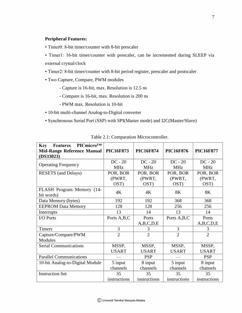
Table 2.1: Comparation Microcontroller.
Key Features PICmicro™
Mid-Range Reference Manual
(DS33023)
PIC16F873 PIC16F874 PIC16F876 PIC16F877
Operating Frequency DC - 20
MHz
DC - 20
MHz
DC - 20
MHz
DC - 20
MHz
RESETS (and Delays) POR, BOR
(PWRT,
OST)
POR, BOR
(PWRT,
OST)
POR, BOR
(PWRT,
OST)
POR, BOR
(PWRT,
OST)
FLASH Program Memory (14-
bit words) 4K 4K 8K 8K
Data Memory (bytes) 192 192 368 368
EEPROM Data Memory 128 128 256 256
Interrupts 13 14 13 14
I/O Ports Ports A,B,C Ports
A,B,C,D,E
Ports A,B,C Ports
A,B,C,D,E
Timers 3 3 3 3
Capture/Compare/PWM
Modules
2 2 2 2
Serial Communications MSSP,
USART
MSSP,
USART
MSSP,
USART
MSSP,
USART
Parallel Communications — PSP — PSP
10-bit Analog-to-Digital Module 5 input
channels
8 input
channels
5 input
channels
8 input
channels
Instruction Set 35
instructions
35
instructions
35
instructions
35
instructions
8
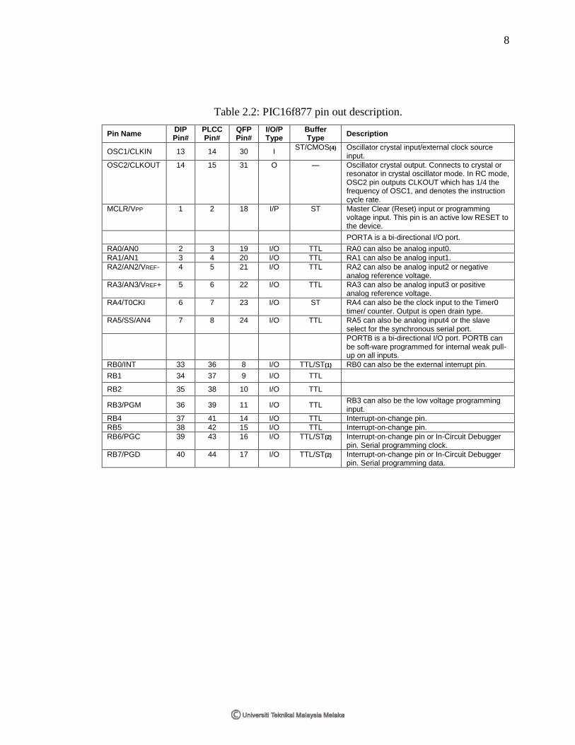
Table 2.2: PIC16f877 pin out description.
Pin Name DIP Pin#
PLCC Pin#
QFP Pin#
I/O/P Type
Buffer Type
Description
OSC1/CLKIN 13 14 30 I ST/CMOS(4) Oscillator crystal input/external clock source
input.
OSC2/CLKOUT 14 15 31 O — Oscillator crystal output. Connects to crystal or resonator in crystal oscillator mode. In RC mode, OSC2 pin outputs CLKOUT which has 1/4 the frequency of OSC1, and denotes the instruction cycle rate.
MCLR/VPP 1 2 18 I/P ST Master Clear (Reset) input or programming voltage input. This pin is an active low RESET to the device.
PORTA is a bi-directional I/O port.
RA0/AN0 2 3 19 I/O TTL RA0 can also be analog input0.
RA1/AN1 3 4 20 I/O TTL RA1 can also be analog input1.
RA2/AN2/VREF- 4 5 21 I/O TTL RA2 can also be analog input2 or negative analog reference voltage.
RA3/AN3/VREF+ 5 6 22 I/O TTL RA3 can also be analog input3 or positive analog reference voltage.
RA4/T0CKI 6 7 23 I/O ST RA4 can also be the clock input to the Timer0 timer/ counter. Output is open drain type.
RA5/SS/AN4 7 8 24 I/O TTL RA5 can also be analog input4 or the slave select for the synchronous serial port.
PORTB is a bi-directional I/O port. PORTB can be soft-ware programmed for internal weak pull-up on all inputs.
RB0/INT 33 36 8 I/O TTL/ST(1) RB0 can also be the external interrupt pin.
RB1 34 37 9 I/O TTL RB2 35 38 10 I/O TTL
RB3/PGM 36 39 11 I/O TTL RB3 can also be the low voltage programming input.
RB4 37 41 14 I/O TTL Interrupt-on-change pin.
RB5 38 42 15 I/O TTL Interrupt-on-change pin.
RB6/PGC 39 43 16 I/O TTL/ST(2) Interrupt-on-change pin or In-Circuit Debugger pin. Serial programming clock.
RB7/PGD 40 44 17 I/O TTL/ST(2) Interrupt-on-change pin or In-Circuit Debugger pin. Serial programming data.

9
2.2.2 Example program for PIC 16f77
list p=pic16f877a
include p16f877a.inc
__config 0x1E72
errorlevel -302 ;Suppress bank warning
CBlock 0x20
N ; Delay registers.
N1
N2
T_OB
T_NoGrass
Turningx
count1
counta
countb
countc
MOTOR
FIXDELAY
visdelay
priority
dataL
COUNTER1
COUNTER2
temp_num
temp_dig
D0
DIGIT
C1
C2
D1
D2
X1
X2
Y1
Y2
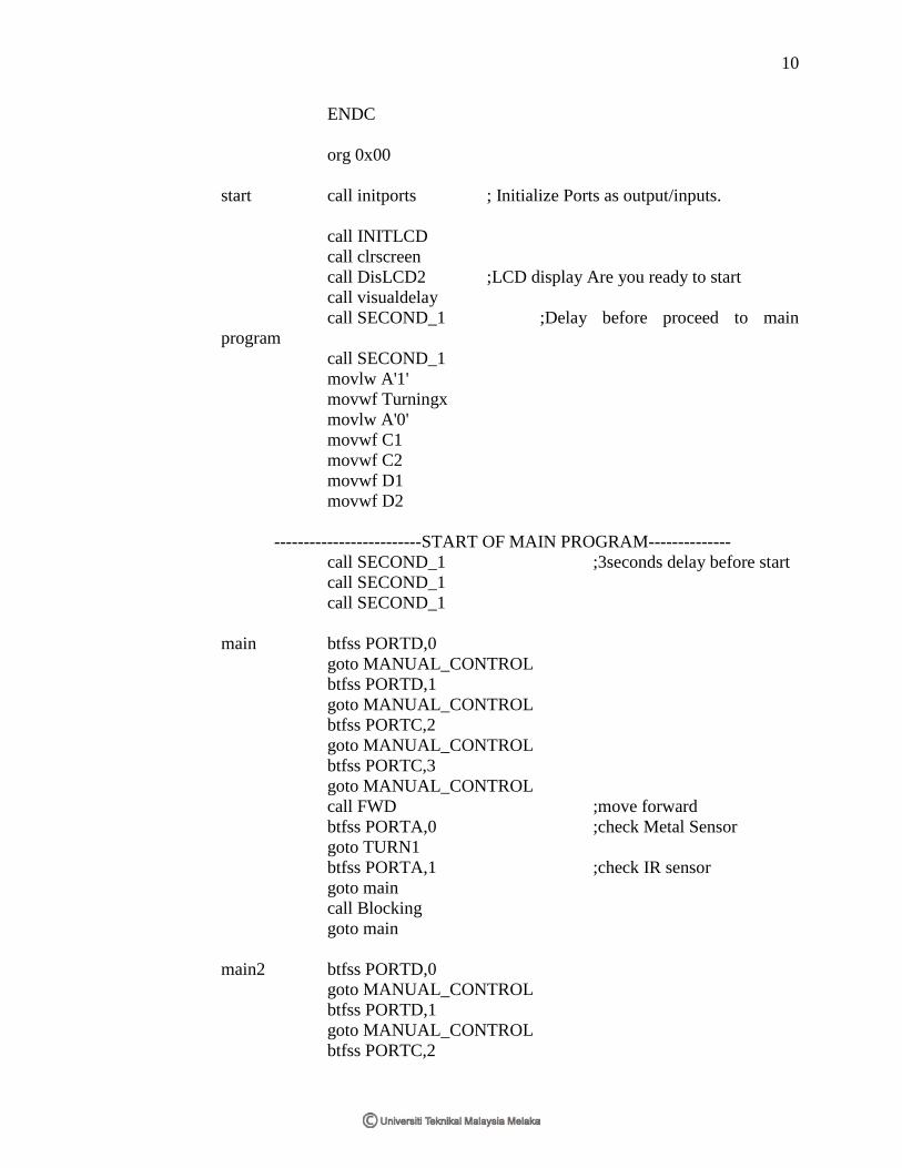
10
ENDC
org 0x00
start call initports ; Initialize Ports as output/inputs.
call INITLCD
call clrscreen
call DisLCD2 ;LCD display Are you ready to start
call visualdelay
call SECOND_1 ;Delay before proceed to main
program
call SECOND_1
movlw A'1'
movwf Turningx
movlw A'0'
movwf C1
movwf C2
movwf D1
movwf D2
-------------------------START OF MAIN PROGRAM--------------
call SECOND_1 ;3seconds delay before start
call SECOND_1
call SECOND_1
main btfss PORTD,0
goto MANUAL_CONTROL
btfss PORTD,1
goto MANUAL_CONTROL
btfss PORTC,2
goto MANUAL_CONTROL
btfss PORTC,3
goto MANUAL_CONTROL
call FWD ;move forward
btfss PORTA,0 ;check Metal Sensor
goto TURN1
btfss PORTA,1 ;check IR sensor
goto main
call Blocking
goto main
main2 btfss PORTD,0
goto MANUAL_CONTROL
btfss PORTD,1
goto MANUAL_CONTROL
btfss PORTC,2