matakuliah: s0522/ aplikasi geosintetik dalam teknik sipil tahun: juli 2005 versi: 01/01 pertemuan...
TRANSCRIPT
Matakuliah : S0522/ Aplikasi Geosintetik Dalam Teknik Sipil
Tahun : Juli 2005
Versi : 01/01
Pertemuan 12APLIKASI DAN PEMILIHAN MATERIAL GEOSINTETIK
Learning Outcomes
Pada akhir pertemuan ini, diharapkan
mahasiswa akan mampu : Mahasiswa mampu membedakan
pemakaian geosintetik sesuai kebutuhan desain di lapangan C6
Outline Materi• Pertimbangan desain• Kondisi tanah• Analisa pemilihan material • Perbandingan penggunaan
geosintetik sesuai kebutuhan dan kondisi lapangan
• Aplikasi geosintetik sesuai kondisi lapangan
Sebagian dari materi ini dikutip dari IGS Lecturer notes No. 17 of 19Geosynthetics in DamsBy Daniele CazzuffiENEL Hydro, Milan, ItalyNo. 18 of 19Geosynthetics in Asphalt PavementsBy Prof. S.F. Brown FEngUniversity of NottinghamNo. 12 of 19Geosynthetics in Erosion ProtectionBy Dr David Elton, P.EAuburn University
Geosynthetics in Sediment and Erosion Control
• Introduction and Applications
• What is it?
• Erosion control is a means of keeping a soil in place or catching a soil after it has been displaced but before it moves into surface waters.
Why Is It Needed?
There are public laws that :
• preclude the polluting of surface waters with sediments
• preserve topographic integrity
• preserve soil for farming
• preserve foundation integrity for structures founded on soil.
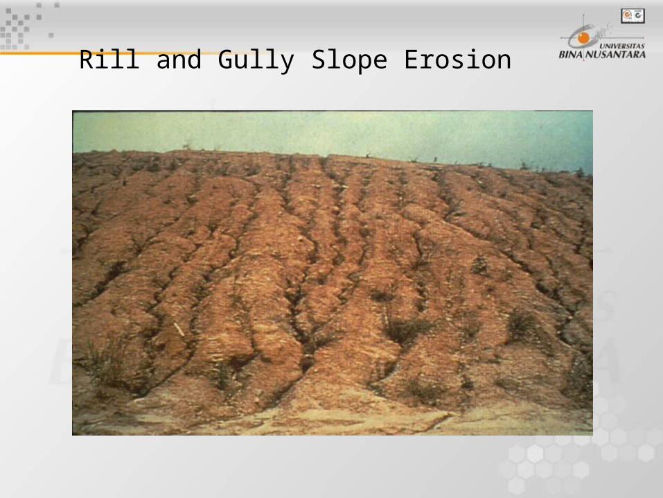
Rill and Gully Slope Erosion
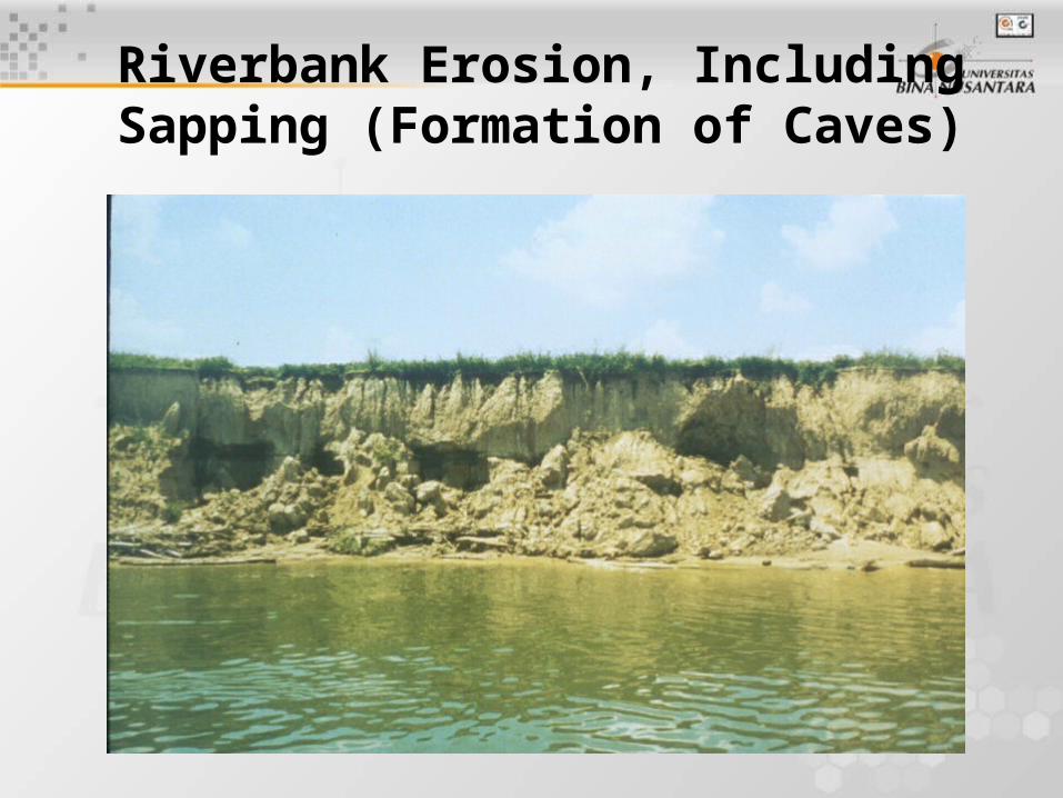
Riverbank Erosion, IncludingSapping (Formation of Caves)
Where Is It Needed?
• It is needed on construction and agricultural sites and natural places where water causes soils to displace.
• In short: where soil and moving water interact at the ground surface
Factors Influencing Types of Erosion
• Rainfall-induced erosion factors:
– intensity and duration of rainfall– slope of land – soil type
• All affect the amount of erosion and the erosion control measures selected.
Factors Influencing Types Of Erosion (Continued)
• Shoreline erosion factors:
– soil type– wave height– beach slope
– duration and intensity of storm
• All affect the amount of erosion.
Factors Influencing Types Of Erosion (Continued)
• Scour:
– The amount of scour, around bridge piers for example, is affected by pier shape, depth of stream, storm duration and channel shape, in addition to soil type.
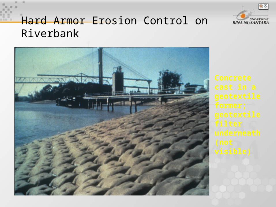
Hard Armor Erosion Control on Riverbank
Concrete cast in a geotextile former; geotextile filter underneath(not visible)
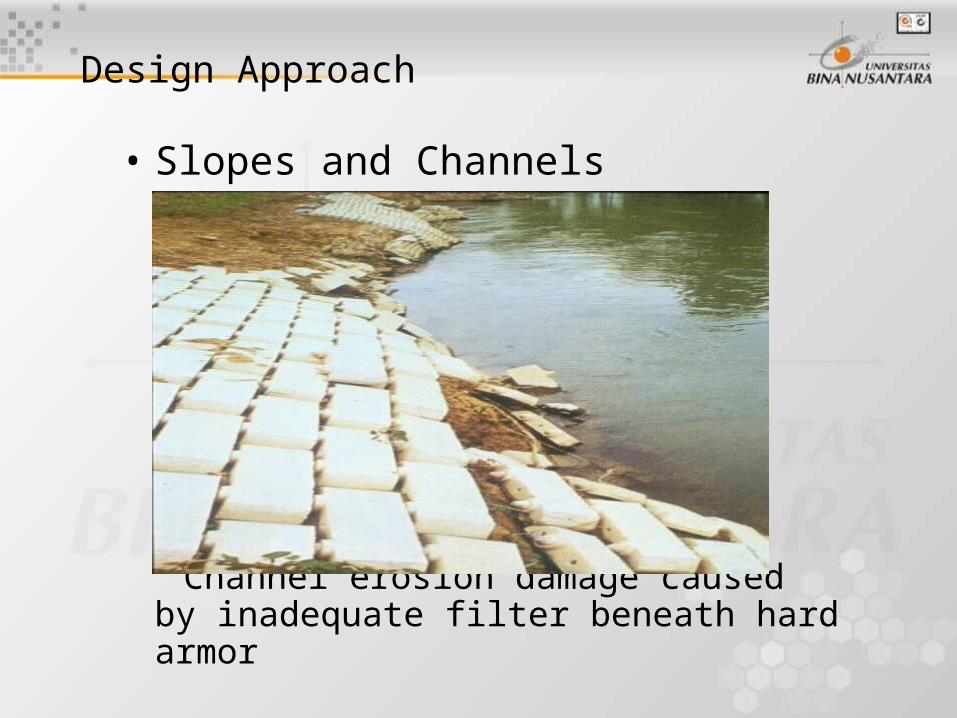
• Slopes and Channels
Channel erosion damage caused by inadequate filter beneath hard armor
Design Approach
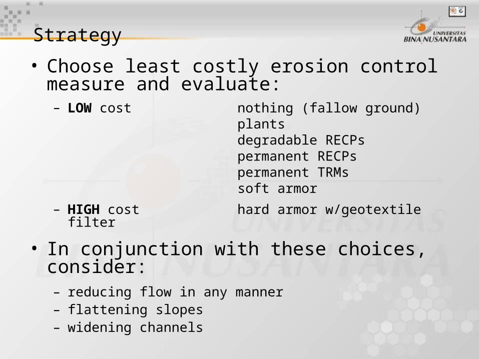
Strategy
• Choose least costly erosion control measure and evaluate:– LOW cost nothing (fallow ground)
plantsdegradable RECPspermanent RECPspermanent TRMssoft armor
– HIGH cost hard armor w/geotextile filter
• In conjunction with these choices, consider:– reducing flow in any manner– flattening slopes– widening channels
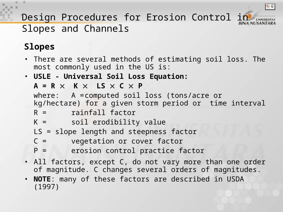
Design Procedures for Erosion Control in Slopes and Channels
Slopes• There are several methods of estimating soil loss. The most
commonly used in the US is: • USLE - Universal Soil Loss Equation:
A = R K LS C Pwhere: A = computed soil loss (tons/acre or kg/hectare) for a
given storm period or time intervalR = rainfall factorK = soil erodibility valueLS = slope length and steepness factorC = vegetation or cover factorP = erosion control practice factor
• All factors, except C, do not vary more than one order of magnitude. C changes several orders of magnitudes.
• NOTE: many of these factors are described in USDA (1997)
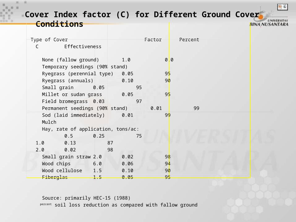
Cover Index factor (C) for Different Ground Cover Conditions
Type of Cover Factor Percent
C Effectiveness None (fallow ground) 1.0 0.0
Temporary seedings (90% stand)
Ryegrass (perennial type) 0.05 95
Ryegrass (annuals) 0.10 90
Small grain 0.05 95
Millet or sudan grass 0.05 95
Field bromegrass 0.03 97
Permanent seedings (90% stand) 0.01 99
Sod (laid immediately) 0.01 99
Mulch
Hay, rate of application, tons/ac:
0.5 0.25 75
1.0 0.13 87
2.0 0.02 98
Small grain straw 2.0 0.02 98
Wood chips 6.0 0.06 94
Wood cellulose 1.5 0.10 90 Fiberglas 1.5 0.05 95
Source: primarily HEC-15 (1988) percent soil loss reduction as compared with fallow ground
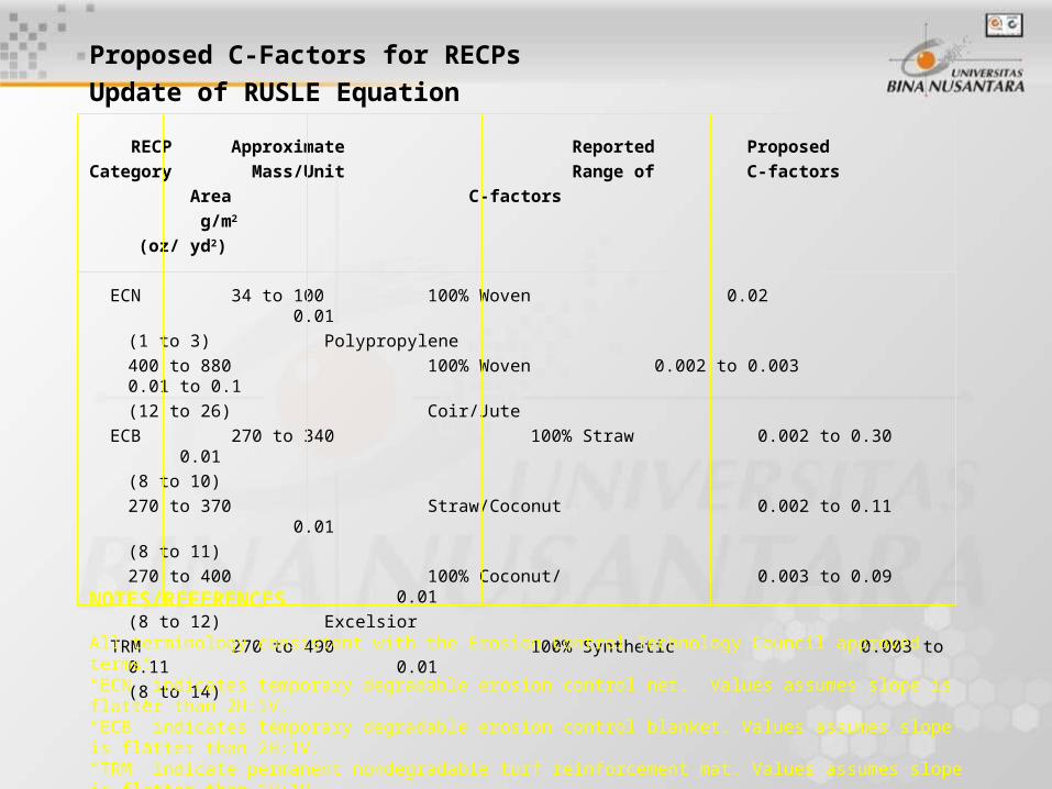
Proposed C-Factors for RECPs
Update of RUSLE Equation
RECP Approximate Reported Proposed
Category Mass/Unit Range of C-factors Area C-factors g/m2
(oz/ yd2)
ECN 34 to 100 100% Woven 0.02 0.01(1 to 3) Polypropylene400 to 880 100% Woven 0.002 to 0.003 0.01 to 0.1(12 to 26) Coir/Jute
ECB 270 to 340 100% Straw 0.002 to 0.30 0.01(8 to 10)270 to 370 Straw/Coconut 0.002 to 0.11 0.01(8 to 11)270 to 400 100% Coconut/ 0.003 to 0.09 0.01(8 to 12) Excelsior
TRM 270 to 490 100% Synthetic 0.003 to 0.11 0.01(8 to 14)
NOTES/REFERENCES
All terminology consistent with the Erosion Control Technology Council approved terms.“ECN” indicates temporary degradable erosion control net. Values assumes slope is flatter than 2H:1V.“ECB” indicates temporary degradable erosion control blanket. Values assumes slope is flatter than 2H:1V.“TRM” indicate permanent nondegradable turf reinforcement mat. Values assumes slope is flatter than 1H:1V.
Procedure
• Calculate A with the C value of a given permanent erosion control solution (usually vegetation)
• Compare A with an acceptable A (e.g. 44 kN/ha/year (2 tons/acre/year))
• If A is acceptable*, check effectiveness of the temporary (degradable) erosion control (RECP) measure used to establish the permanent erosion control solution over the life of the RECP. Choose a temporary solution with a small enough C to satisfy regulations.
• *typically, acceptance is based on government regulations. If A is unacceptable for permanent solution (vegetation), try vegetation plus turf reinforcement mat for long term solution. C values available from test or manufacturers.
• If that combination produces a satisfactory A, check A for temporary erosion control solution used while permanent solution is taking hold.
Channel Linings
• Two Common Methods of Analysis:
– Permissible velocity in channel
– Permissible shear stress in channel
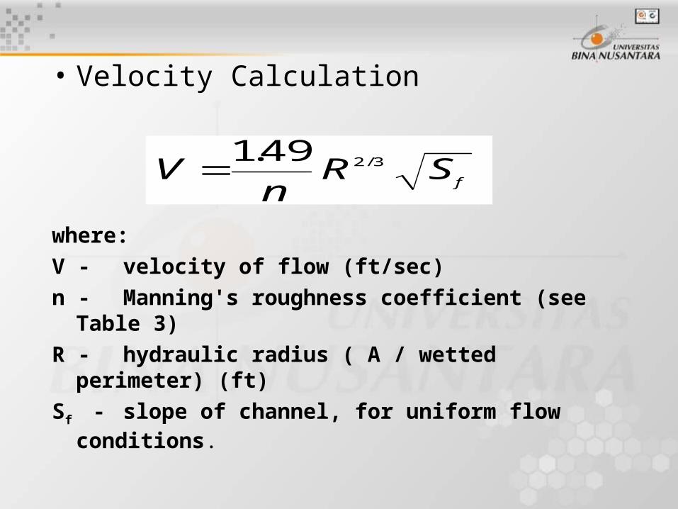
• Velocity Calculation
where:
V - velocity of flow (ft/sec)
n - Manning's roughness coefficient (see Table 3)
R - hydraulic radius ( A / wetted perimeter) (ft)
Sf - slope of channel, for uniform flow conditions.
VnR S
f
149 2 3. /
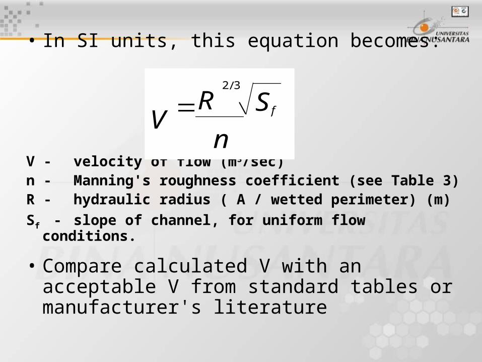
• In SI units, this equation becomes:
V - velocity of flow (m3/sec)n - Manning's roughness coefficient (see Table 3)R - hydraulic radius ( A / wetted perimeter) (m)
Sf - slope of channel, for uniform flow conditions.
• Compare calculated V with an acceptable V from standard tables or manufacturer's literature
Vn
R Sf2 3/
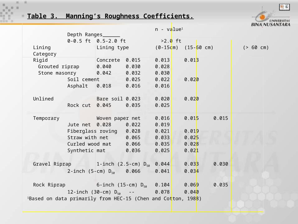
Table 3. Manning’s Roughness Coefficients.
n - value1
Depth Ranges 0-0.5 ft 0.5-2.0 ft >2.0 ft
Lining Lining type (0-15cm) (15-60 cm) (> 60 cm) Category Rigid Concrete 0.015 0.013 0.013
Grouted riprap 0.040 0.0300.028
Stone masonry 0.042 0.0320.030
Soil cement 0.025 0.022 0.020 Asphalt 0.018 0.016 0.016
Unlined Bare soil 0.023 0.020 0.020 Rock cut 0.045 0.035 0.025
Temporary Woven paper net 0.016 0.015 0.015 Jute net 0.028 0.022 0.019 Fiberglass roving 0.028 0.021 0.019 Straw with net 0.065 0.033
0.025 Curled wood mat 0.066 0.035 0.028 Synthetic mat 0.036 0.025
0.021
Gravel Riprap 1-inch (2.5-cm) D50 0.044 0.033 0.030
2-inch (5-cm) D50 0.066 0.041 0.034
Rock Riprap 6-inch (15-cm) D50 0.104 0.069 0.035
12-inch (30-cm) D50 -- 0.078 0.040
1Based on data primarily from HEC-15 (Chen and Cotton, 1988)
Notes:
• Values listed are representative values for the respective depth ranges.
• Manning’s roughness coefficients, n, vary with the flow depth.
• n-values for vegetative linings are found in Chen and Cotton (1988) (HEC-15) on pages 42 - 46.
• Another method is to evaluate the shear stress on the ground surface caused by the running water. (Method follows).
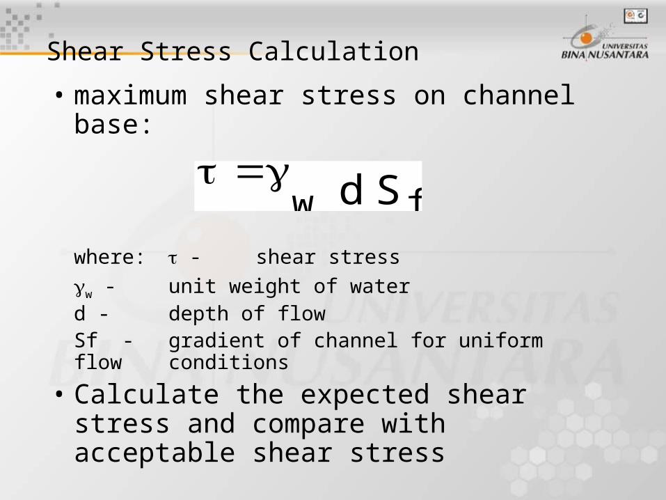
• maximum shear stress on channel base:
where: - shear stress
w - unit weight of waterd - depth of flowSf - gradient of channel for uniform flow
conditions
• Calculate the expected shear stress and compare with acceptable shear stress
Shear Stress Calculation
w fd S
Design Variables
• increasing the width/depth ratio of channel reduces
– channel slope: flatter reduces (note: 10% is considered a "steep Channel". Sf > 10% usually requires hard armor)
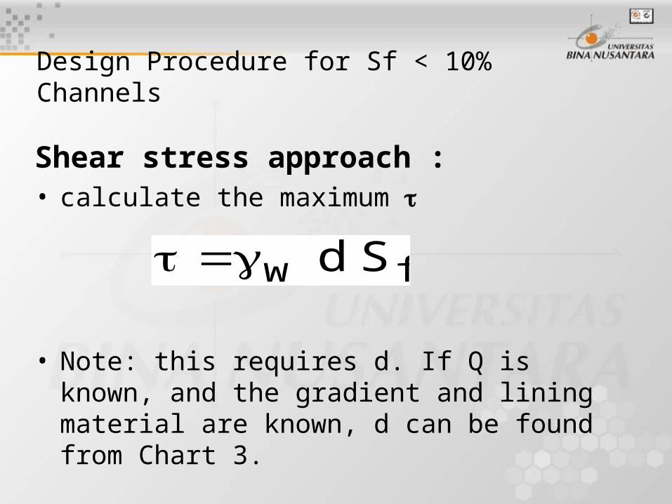
Shear stress approach :• calculate the maximum
• Note: this requires d. If Q is known, and the gradient and lining material are known, d can be found from Chart 3.
w fd S
Design Procedure for Sf < 10% Channels
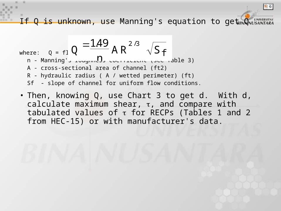
If Q is unknown, use Manning's equation to get Q
where: Q = flow (cfs)n - Manning's roughness coefficient (see Table 3)A - cross-sectional area of channel (ft2)R - hydraulic radius ( A / wetted perimeter) (ft)Sf - slope of channel for uniform flow conditions.
• Then, knowing Q, use Chart 3 to get d. With d, calculate maximum shear, , and compare with tabulated values of for RECPs (Tables 1 and 2 from HEC-15) or with manufacturer's data.
Qn
A R Sf149 2 3. /

In SI units, this equation is:
where:Q = flow (m3/sec)n - Manning's roughness coefficient (see Table 3)A - cross-sectional area of channel (m2)R - hydraulic radius ( A / wetted perimeter) (m)Sf - slope of channel for uniform flow conditions.
Qn
AR Sf
2 3/
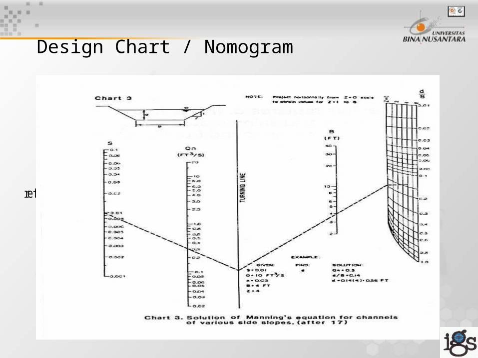
Design Chart / Nomogram
ref: Chen, Y.H. and G.K. Cotton (1988)
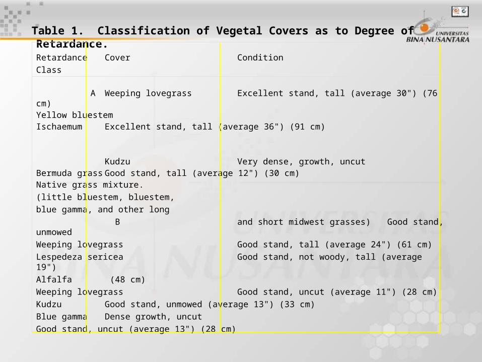
Table 1. Classification of Vegetal Covers as to Degree of Retardance. Retardance Cover Condition
Class A Weeping lovegrass Excellent stand, tall (average 30") (76 cm)
Yellow bluestemIschaemum Excellent stand, tall (average 36") (91 cm)
Kudzu Very dense, growth, uncutBermuda grass Good stand, tall (average 12") (30 cm)Native grass mixture.(little bluestem, bluestem,blue gamma, and other long
B and short midwest grasses) Good stand, unmowedWeeping lovegrass Good stand, tall (average 24") (61 cm)Lespedeza sericea Good stand, not woody, tall (average 19")Alfalfa (48 cm)Weeping lovegrass Good stand, uncut (average 11") (28 cm)Kudzu Good stand, unmowed (average 13") (33 cm)Blue gamma Dense growth, uncut
Good stand, uncut (average 13") (28 cm)
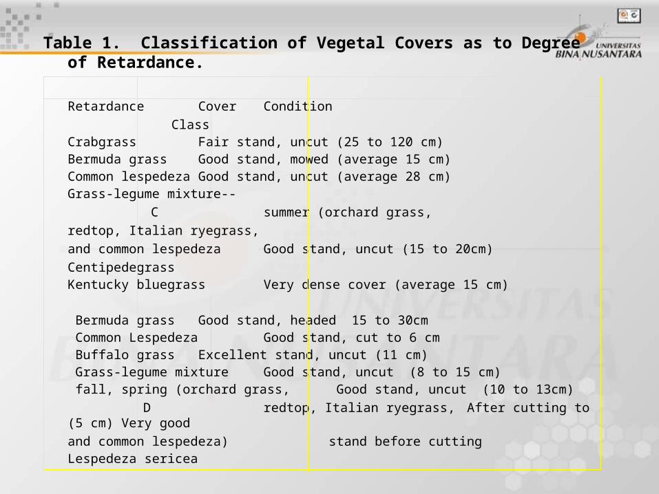
Table 1. Classification of Vegetal Covers as to Degree of Retardance.
Retardance Cover Condition Class
Crabgrass Fair stand, uncut (25 to 120 cm)Bermuda grass Good stand, mowed (average 15 cm)Common lespedeza Good stand, uncut (average 28 cm)Grass-legume mixture--
C summer (orchard grass,redtop, Italian ryegrass,and common lespedeza Good stand, uncut (15 to
20cm)Centipedegrass Kentucky bluegrass Very dense cover (average 15 cm)
Bermuda grass Good stand, headed 15 to 30cm Common Lespedeza Good stand, cut to 6 cm Buffalo grass Excellent stand, uncut (11 cm) Grass-legume mixture Good stand, uncut (8 to
15 cm) fall, spring (orchard grass, Good stand, uncut (10 to 13cm)
D redtop, Italian ryegrass, After cutting to (5 cm) Very good
and common lespedeza) stand before cuttingLespedeza sericea
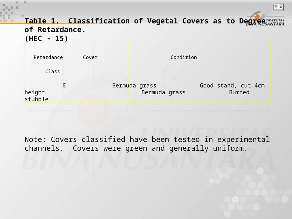
Table 1. Classification of Vegetal Covers as to Degree of Retardance.(HEC - 15)
Retardance Cover Condition
Class
E Bermuda grass Good stand, cut 4cm heightBermuda grass Burned stubble
Note: Covers classified have been tested in experimental channels. Covers were green and generally uniform.
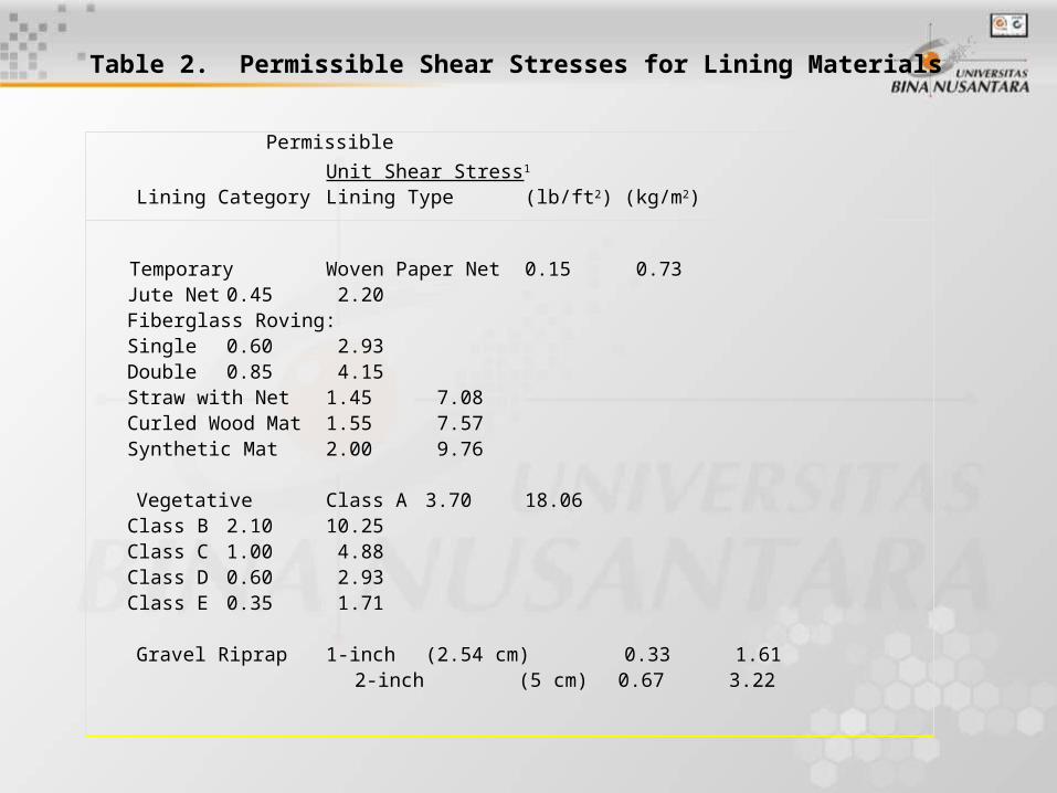
Table 2. Permissible Shear Stresses for Lining Materials
Permissible
Unit Shear Stress1
Lining Category Lining Type (lb/ft2)(kg/m2)
Temporary Woven Paper Net 0.15 0.73Jute Net 0.45 2.20Fiberglass Roving:Single 0.60 2.93Double 0.85 4.15Straw with Net 1.45 7.08Curled Wood Mat 1.55 7.57Synthetic Mat 2.00 9.76
Vegetative Class A 3.70 18.06Class B 2.10 10.25Class C 1.00 4.88Class D 0.60 2.93Class E 0.35 1.71
Gravel Riprap 1-inch (2.54 cm) 0.33 1.61 2-inch (5 cm) 0.67 3.22
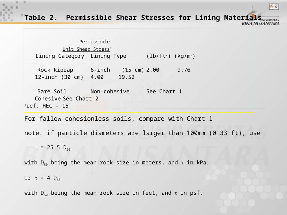
Table 2. Permissible Shear Stresses for Lining Materials
Permissible
Unit Shear Stress1
Lining Category Lining Type (lb/ft2)(kg/m2)
Rock Riprap 6-inch (15 cm) 2.00 9.7612-inch (30 cm) 4.00 19.52
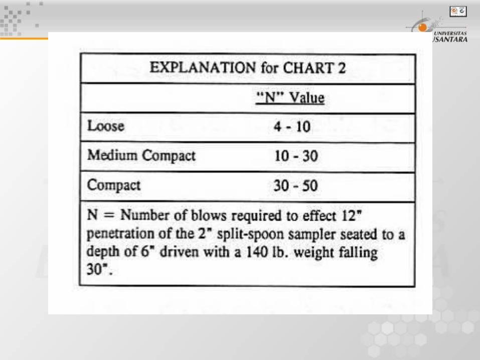
Bare Soil Non-cohesive See Chart 1Cohesive See Chart 2
1ref: HEC - 15
For fallow cohesionless soils, compare with Chart 1
note: if particle diameters are larger than 100mm (0.33 ft), use
= 25.5 D50
with D50 being the mean rock size in meters, and in kPa,
or = 4 D50
with D50 being the mean rock size in feet, and in psf.

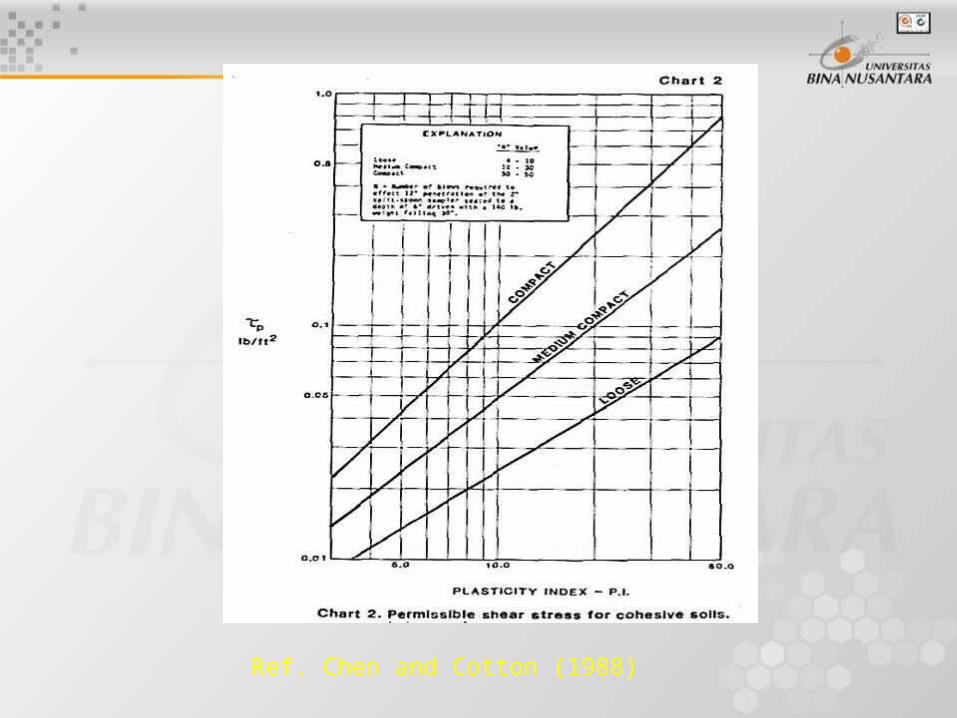
Ref. Chen and Cotton (1988)

Erosion Control Using Geosynthetics
Applications:• Introduction• Useful in scour, surface and shoreline
protection• Geosynthetic functions include:
– filtration– containment (bags)– protection– providing a medium for plant growth
Erosion Control Using Geosynthetics
Scour Applications
– Bridge pier footing
– Canal Lining
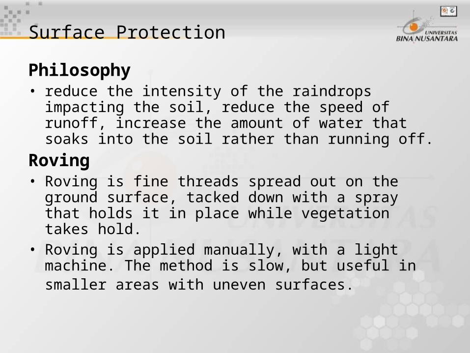
Surface Protection
Philosophy• reduce the intensity of the raindrops impacting the soil,
reduce the speed of runoff, increase the amount of water that soaks into the soil rather than running off.
Roving• Roving is fine threads spread out on the ground surface,
tacked down with a spray that holds it in place while vegetation takes hold.
• Roving is applied manually, with a light machine. The method is slow, but useful in smaller areas with uneven surfaces.
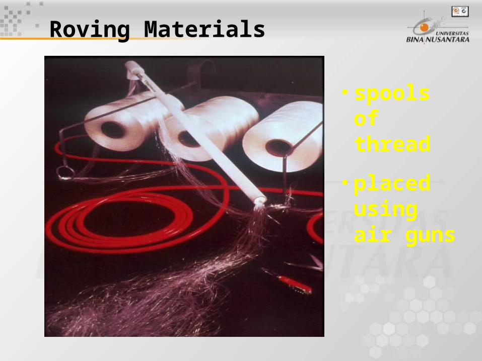
Roving Materials
• spools of thread
• placed using air guns
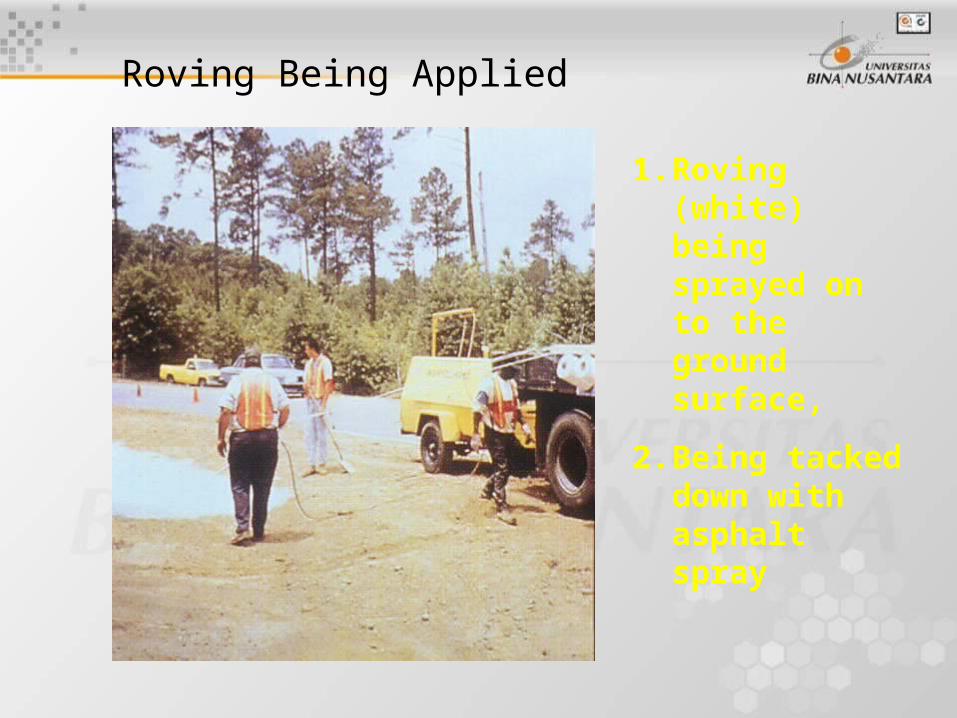
Roving Being Applied
1. Roving (white) being sprayed on to the ground surface,
2. Being tacked down with asphalt spray
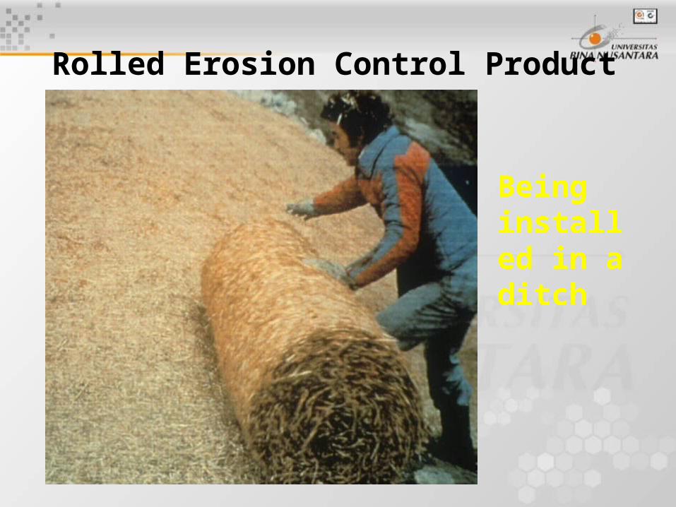
Rolled Erosion Control Product
Being installed in a ditch
Permanent Installations (Permanent Erosion and Revegetation Mats)
Soft PERMs
• Turf Reinforcement Mats (TRMs)
– TRMs are typically placed on the surface and then filled in
with soil. They reinforce the ground surface, making erosion
more difficult. The TERM holds the soil in place while
vegetation takes hold.
• Erosion Control and Revegetation Mats (ECRMs)
– These combine surface control and surface slope
stabilization at the same time.
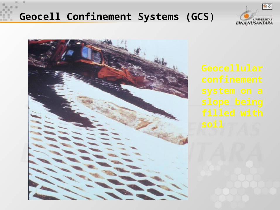
Geocell Confinement Systems (GCS)
Geocellular confinement system on a slope being filled with soil
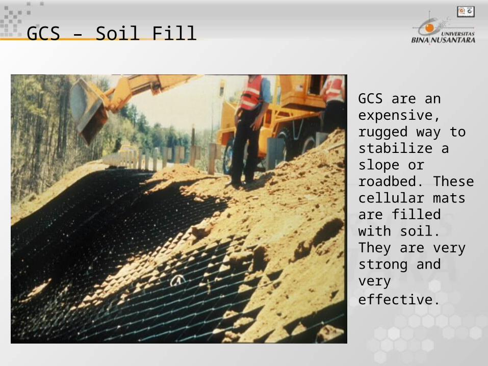
GCS – Soil Fill
GCS are an expensive, rugged way to stabilize a slope or roadbed. These cellular mats are filled with soil. They are very strong and very effective.
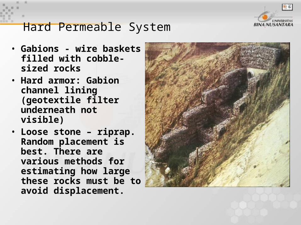
Hard Permeable System
• Gabions - wire baskets filled with cobble-sized rocks
• Hard armor: Gabion channel lining (geotextile filter underneath not visible)
• Loose stone – riprap. Random placement is best. There are various methods for estimating how large these rocks must be to avoid displacement.
Hard Armor
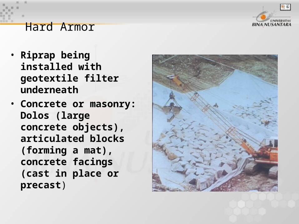
• Riprap being installed with geotextile filter underneath
• Concrete or masonry: Dolos (large concrete objects), articulated blocks (forming a mat), concrete facings (cast in place or precast)