dcg 125013 livre ok - toko online terpercaya · compliant with standard iec 60439-1. it ... >...
TRANSCRIPT
En
clo
su
res
& a
cc
esso
rie
s
sb_1
03
_a_1
_cat
sb_0
84
_a_1
_cat
sb_0
77
_a_1
_cat
sb_1
95
_a_1
_cat
Busbar supportsBusbar
Busbar supports with fixed interphase
Busbar supports with adjustable interphase
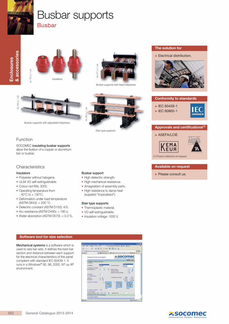
Insulators
Stair type supports
Function
Characteristics
SOCOMEC insulating busbar supports allow the fixation of a copper or aluminium bar or busbar.
Insulators
Polyester without halogene.
UL94 VO self-extinguishable.
Colour red RAL 3002.
Operating temperature from - 40°C to + 130°C.
Deformation under load temperature
Dielectric constant (ASTM D150): 4/5.
Arc resistance (ASTM D495): > 180 s.
Busbar support
High dielectric strength.
High mechanical resistance.
Amagnetism of assembly parts.
High resistance to damp heat (supplied "tropicalised").
Stair type supports
Thermoplastic material.
VO self-extinguishable.
Insulation voltage: 1000 V.
> Electrical distribution.
The solution for
> Please consult us.
Available on request
> ASEFA/LCIE
Approvals and certifications(1)
Mechanical systems is a software which is used to size bar sets. It defines the best bar section and distance between each support for the electrical characteristics of the panel compliant with standard IEC 60439-1. It runs in a Windows® 95, 98, 2000, NT ou XP environment.
> IEC 60439-1 > IEC 60865-1
Conformity to standards
(1) Product reference on request.
Software tool for size selection
562 General Catalogue 2013-2014
Busbar supportsBusbar
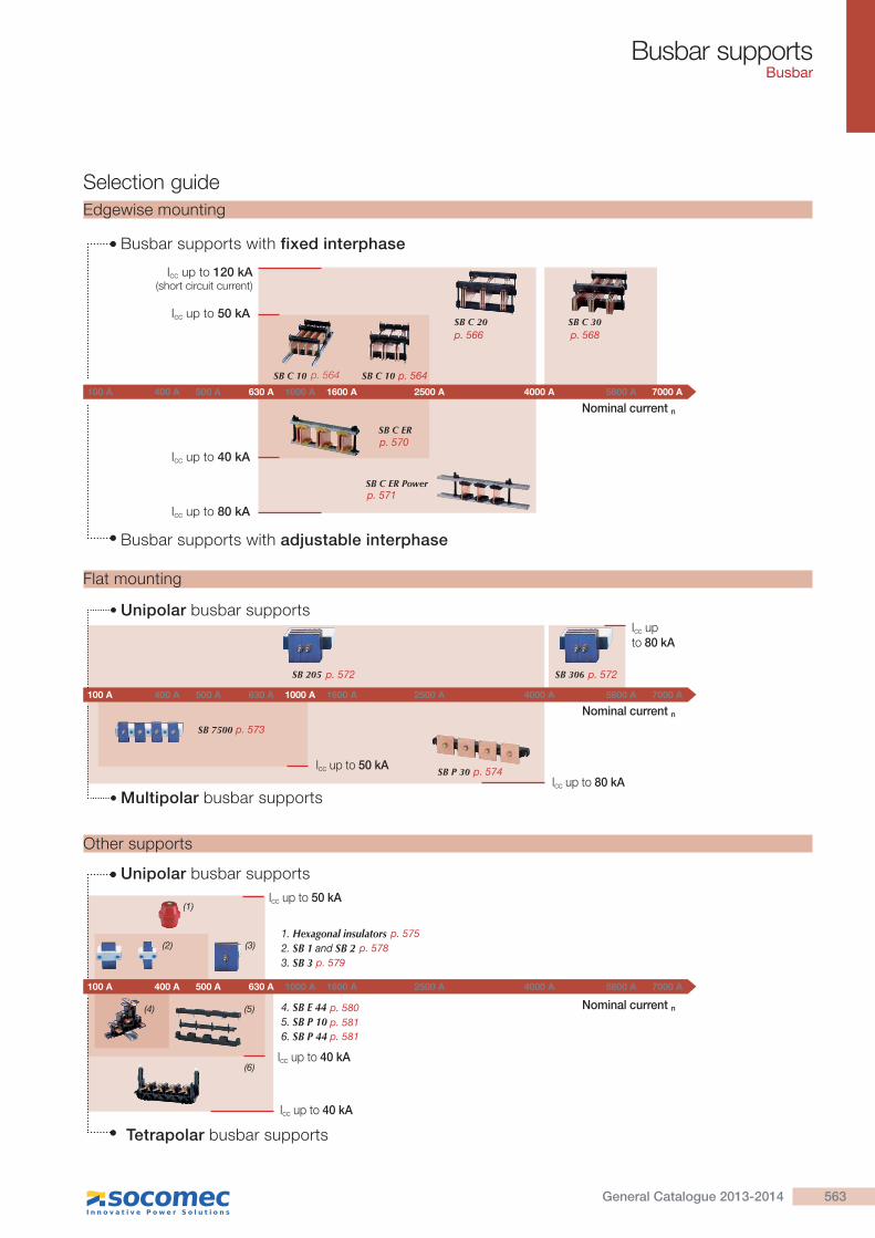
Selection guide
100 A 400 A 500 A 630 A 1000 A 1600 A 2500 A 4000 A 5800 A 7000 A
4. SB E 445. SB P 106. SB P 44
1. Hexagonal insulators2. SB 1 and SB 2
3. SB 3
(4) (5)
(6)
(1)
(2) (3)
Nominal current n
Unipolar busbar supports
Tetrapolar busbar supports
Icc up to 40 kA
Icc up to 40 kA
Icc up to 50 kA
100 A 400 A 500 A 630 A 1000 A 1600 A 2500 A 4000 A 5800 A 7000 A
SB 205 SB 306
SB 7500
SB P 30
Nominal current n
Unipolar busbar supports
Multipolar busbar supports
Icc up to 80 kA
Icc up to 80 kA
Icc up to 50 kA
Edgewise mounting
100 A 400 A 500 A 630 A 1000 A 1600 A 2500 A 4000 A 5800 A 7000 A
SB C 10 SB C 10
SB C 20 SB C 30
SB C ER
SB C ER Power
Nominal current n
Icc up to 50 kA
Icc up to 120 kA(short circuit current)
Busbar supports with fixed interphase
Busbar supports with adjustable interphase
Icc up to 40 kA
Icc up to 80 kA
Flat mounting
Other supports
563General Catalogue 2013-2014
p. 575
p. 573
p. 572 p. 572
p. 570
p. 564 p. 564
p. 566 p. 568
p. 571
p. 574
p. 578
p. 579
p. 580
p. 581
p. 581
Busbar supportsBusbar
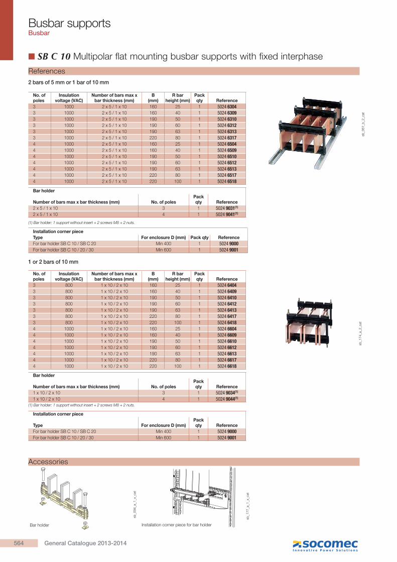
SB C 10 Multipolar flat mounting busbar supports with fixed interphase
2 bars of 5 mm or 1 bar of 10 mm
1 or 2 bars of 10 mm
No. of poles
Insulation voltage (VAC)
Number of bars max x bar thickness (mm)
B(mm)
R bar height (mm)
Pack qty Reference
3 800 1 x 10 / 2 x 10 160 25 1 5024 64043 800 1 x 10 / 2 x 10 160 40 1 5024 64093 800 1 x 10 / 2 x 10 190 50 1 5024 64103 800 1 x 10 / 2 x 10 190 60 1 5024 64123 800 1 x 10 / 2 x 10 190 63 1 5024 64133 800 1 x 10 / 2 x 10 220 80 1 5024 64173 800 1 x 10 / 2 x 10 220 100 1 5024 64184 1000 1 x 10 / 2 x 10 160 25 1 5024 66044 1000 1 x 10 / 2 x 10 160 40 1 5024 66094 1000 1 x 10 / 2 x 10 190 50 1 5024 66104 1000 1 x 10 / 2 x 10 190 60 1 5024 66124 1000 1 x 10 / 2 x 10 190 63 1 5024 66134 1000 1 x 10 / 2 x 10 220 80 1 5024 66174 1000 1 x 10 / 2 x 10 220 100 1 5024 6618
No. of poles
Insulation voltage (VAC)
Number of bars max x bar thickness (mm)
B(mm)
R bar height (mm)
Pack qty Reference
3 1000 2 x 5 / 1 x 10 160 25 1 5024 63043 1000 2 x 5 / 1 x 10 160 40 1 5024 63093 1000 2 x 5 / 1 x 10 190 50 1 5024 63103 1000 2 x 5 / 1 x 10 190 60 1 5024 63123 1000 2 x 5 / 1 x 10 190 63 1 5024 63133 1000 2 x 5 / 1 x 10 220 80 1 5024 63174 1000 2 x 5 / 1 x 10 160 25 1 5024 65044 1000 2 x 5 / 1 x 10 160 40 1 5024 65094 1000 2 x 5 / 1 x 10 190 50 1 5024 65104 1000 2 x 5 / 1 x 10 190 60 1 5024 65124 1000 2 x 5 / 1 x 10 190 63 1 5024 65134 1000 2 x 5 / 1 x 10 220 80 1 5024 65174 1000 2 x 5 / 1 x 10 220 100 1 5024 6518
sb_0
61
_b_2
_cat
References
Bar holder
Number of bars max x bar thickness (mm) No. of polesPack qty Reference
2 x 5 / 1 x 10 3 1 5024 9031(1)
2 x 5 / 1 x 10 4 1 5024 9041(1)
(1) Bar holder: 1 support without insert + 2 screws M8 + 2 nuts.
sb_1
74_a
_2_c
at
Installation corner piece
Type For enclosure D (mm) Pack qty Reference
For bar holder SB C 10 / SB C 20 Min 400 1 5024 9000For bar holder SB C 10 / 20 / 30 Min 600 1 5024 9001
Bar holder
Number of bars max x bar thickness (mm) No. of polesPack qty Reference
1 x 10 / 2 x 10 3 1 5024 9034(1)
1 x 10 / 2 x 10 4 1 5024 9044(1)
(1) Bar holder: 1 support without insert + 2 screws M8 + 2 nuts.
Installation corner piece
Type For enclosure D (mm)Pack qty Reference
For bar holder SB C 10 / SB C 20 Min 400 1 5024 9000For bar holder SB C 10 / 20 / 30 Min 600 1 5024 9001
sb_1
77_a
_1_x
_cat
sb_0
94_a
_1_x
_cat
Accessories
Bar holder Installation corner piece for bar holder
564 General Catalogue 2013-2014

Busbar supportsBusbar
(1) Admissible nominal current for a temperature in the cabinet of 45°C and 80°C for the bars. Other assembly configurations: please consult us.
Max. L (distance between centres of supports in mm) for
peak Isc 15 kA 24 kA 48 kA 63 kA 82 kA 114 kA
rms Isc 9 kA 12 kA 23 kA 30 kA 39 kA 52 kA
Bar x no. d (mm) Iz (A)(1)
25 x 5 x 1 775 475 225 175 140 100 60 330
25 x 5 x 2 675 425 200 160 125 60 590
40 x 5 x 1 1000 625 300 225 175 130 60 500
40 x 5 x 2 950 575 275 225 170 125 60 850
50 x 5 x 1 1000 700 350 250 200 130 60 600
50 x 5 x 2 1000 675 325 250 200 145 60 1050
60 x 5 x 1 1000 775 375 300 225 130 60 700
60 x 5 x 2 1000 775 375 300 225 165 60 1200
63 x 5 x 1 1000 800 400 300 225 130 60 700
63 x 5 x 2 1000 800 400 300 225 170 60 1250
80 x 5 x 1 1000 950 475 350 225 125 60 900
80 x 5 x 2 1000 975 475 375 275 200 60 1550
100 x 5 x 1 1000 1000 550 400 225 125 60 1100
100 x 5 x 2 1000 1000 575 425 325 225 60 1900
Max. L (distance between centres of supports in mm) for
peak Isc 15 kA 24 kA 48 kA 63 kA 82 kA 114 kA
rms Isc 9 kA 12 kA 23 kA 30 kA 39 kA 52 kA
Bar x no. d (mm) Iz (A)(1)
25 x 10 x 1 1000 1000 500 375 275 200 65
25 x 10 x 2 1000 1000 525 400 300 200 90 850
40 x 10 x 1 1000 1000 650 475 375 250 65 700
40 x 10 x 2 1000 1000 700 525 400 275 90 1250
50 x 10 x 1 1000 1000 725 550 425 300 65 850
50 x 10 x 2 1000 1000 800 600 475 325 90 1550
60 x 10 x 1 1000 1000 800 625 475 325 65 1000
60 x 10 x 2 1000 1000 900 675 525 350 90 1800
63 x 10 x 1 1000 1000 825 625 475 350 65 1050
63 x 10 x 2 1000 1000 925 700 550 350 90 1850
80 x 10 x 1 1000 1000 975 725 550 400 65 1300
80 x 10 x 2 1000 1000 1000 850 650 350 90 2300
100 x 10 x 1 1000 1000 1000 850 650 400 65 1550
100 x 10 x 2 1000 1000 1000 975 675 350 90 2750
Mounting of one or two bars per pole
Characteristics
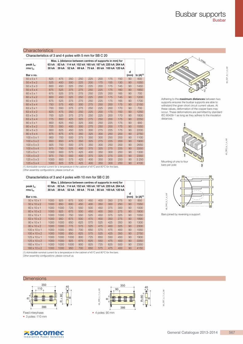
Adhering to the maximum distances between two supports ensures the busbar supports are able to withstand the given short circuit current values. At these values, deformation of the copper bars may occur. These deformations are permitted by standard IEC 60439-1 as long as they adhere to the insulation distances.
(1) Admissible nominal current for a temperature in the cabinet of 45°C and 80°C for the bars. Other assembly configurations: please consult us.
L max.
d
sb_0
21
_b_1
_gb
_cat
sb_0
54_b
_1_x
_cat
sb_0
45_b
_1_x
_cat
Bars joined by reversing a support
2 bars of 5 mm or 1 bar of 10 mm 1 or 2 bars of 10 mm
Fixed interphase:
3 poles 2 x 5, 1 x 10: 75 mm
4 poles thickness bars. 5 mm: 60 poles thickness bars. 10 mm: 65 mm.
Dimensions
Fixed interphase:
3 poles 1 bar of 10 mm: 75 mm 2 bars of 10 mm per pole: 90 mm
4 poles 1 or 2 bars of 10 mm 90 mm.
R
250
274
75
R+
66 B
20
R
250
65
60 20
R+
66 B
sb_1
12_e
_1_x
_cat
R
250
274
90
75
sb_1
87_b
_1_x
_cat
37490
35020
R+
66 B
sb_1
78_b
_1_x
_cat
Characteristics of 3 and 4 poles with 5 mm for SB C 10
Characteristics of 3 and 4 poles with 10 mm for SB C 10
565General Catalogue 2013-2014
Busbar supportsBusbar
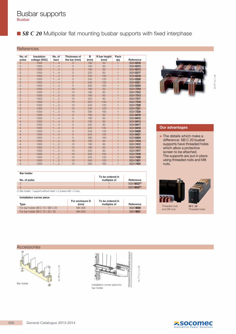
SB C 20 Multipolar flat mounting busbar supports with fixed interphase
Accessories
Installation corner piece for bar holder
sb_0
93_a
_1_x
_cat
sb_1
77_a
_1_x
_cat
Bar holder
References
No. of poles
Insulation voltage (VAC)
No. ofbars
Thickness ofthe bar (mm)
B(mm)
R bar height (mm)
Pack qty Reference
3 1000 1 … 4 5 190 50 1 5024 83103 1000 1 … 4 5 190 60 1 5024 83123 1000 1 … 4 5 190 63 1 5024 83133 1000 1 … 4 5 220 80 1 5024 83173 1000 1 … 4 5 220 100 1 5024 83183 1000 1 … 4 5 245 120 1 5024 83203 1000 1 … 4 5 245 125 1 5024 83213 1000 1 … 4 5 280 160 1 5024 83243 1000 1 … 2 10 190 50 1 5024 73103 1000 1 … 2 10 190 60 1 5024 73123 1000 1 … 2 10 190 63 1 5024 73133 1000 1 … 2 10 220 80 1 5024 73173 1000 1 … 2 10 220 100 1 5024 73183 1000 1 … 2 10 245 120 1 5024 73203 1000 1 … 2 10 245 125 1 5024 73213 1000 1 … 2 10 280 160 1 5024 73244 1000 1 … 4 5 190 50 1 5024 84104 1000 1 … 4 5 190 60 1 5024 84124 1000 1 … 4 5 190 63 1 5024 84134 1000 1 … 4 5 220 80 1 5024 84174 1000 1 … 4 5 220 100 1 5024 84184 1000 1 … 4 5 245 120 1 5024 84204 1000 1 … 4 5 245 125 1 5024 84214 1000 1 … 4 5 280 160 1 5024 84244 1000 1 … 2 10 190 50 1 5024 74104 1000 1 … 2 10 190 60 1 5024 74124 1000 1 … 2 10 190 63 1 5024 74134 1000 1 … 2 10 220 80 1 5024 74174 1000 1 … 2 10 220 100 1 5024 74184 1000 1 … 2 10 245 120 1 5024 74204 1000 1 … 2 10 245 125 1 5024 74214 1000 1 … 2 10 280 160 1 5024 7424
Installation corner piece
TypeFor enclosure D
(mm)To be ordered in
multiples of Reference
For bar holder SB C 10 / SB C 20 Min 400 1 5024 9000For bar holder SB C 10 / 20 / 30 Min 600 1 5024 9001
Bar holder
No. of polesTo be ordered in
multiples of Reference
3 1 5024 9032(1)
4 1 5024 9042(1)
(1) Bar holder: 1 support without insert + 2 screws M8 + 2 nuts.
sb_0
77
_a_1
_cat
> The details which make a difference: SB C 20 busbar supports have threaded holes which allow a protective screen to be attached. The supports are put in place using threaded rods and M8 nuts.
Our advantages
SB C 20Threaded holes
Threaded rods and M8 nuts.
566 General Catalogue 2013-2014
Busbar supportsBusbar
Dimensions
Fixed interphase:
3 poles: 110 mm
4 poles: 90 mm
R
35040
110
386
R +
80
B
sb_0
66_c
_1_x
_cat
R
35090
386
40
R+
80 B
sb_0
67_c
_1_x
_cat
Adhering to the maximum distances between two supports ensures the busbar supports are able to withstand the given short circuit current values. At these values, deformation of the copper bars may occur. These deformations are permitted by standard IEC 60439-1 as long as they adhere to the insulation distances.
Bars joined by reversing a support
L max.
d
sb_0
21
_b_1
_x_c
at
Max. L (distance between centres of supports in mm) for
peak Isc 63 kA 82 kA 114 kA 152 kA 165 kA 187 kA 220 kA 264 kA
rms Isc 30 kA 39 kA 52 kA 69 kA 75 kA 85 kA 100 kA 120 kA
Bar x no.d
(mm) Iz (A)(1)
50 x 5 x 1 625 475 350 250 225 200 175 150 90 600
50 x 5 x 2 525 400 300 225 200 175 155 130 90 1050
50 x 5 x 3 600 450 325 250 225 200 175 145 90 1450
50 x 5 x 4 675 525 375 275 250 225 175 160 90 1850
60 x 5 x 1 675 525 375 275 250 225 200 165 90 700
60 x 5 x 2 600 450 325 250 225 200 175 145 90 1200
60 x 5 x 3 675 525 375 275 250 225 175 165 90 1700
60 x 5 x 4 750 575 400 300 275 250 200 175 90 2150
63 x 5 x 1 700 550 375 275 250 225 200 170 90 700
63 x 5 x 2 625 475 350 250 225 200 175 150 90 1250
63 x 5 x 3 700 525 375 275 250 225 200 170 90 1800
63 x 5 x 4 775 600 425 325 275 250 200 175 90 2250
80 x 5 x 1 800 625 450 325 300 250 225 175 90 900
80 x 5 x 2 725 550 400 300 275 250 200 175 90 1550
80 x 5 x 3 800 625 450 325 300 275 225 175 90 2200
80 x 5 x 4 875 675 475 350 325 300 250 200 90 2750
100 x 5 x 1 900 700 500 375 350 300 250 200 90 1100
100 x 5 x 2 850 650 475 350 325 275 225 200 90 1900
100 x 5 x 3 925 700 500 375 350 300 250 200 90 2650
100 x 5 x 4 975 750 525 400 375 325 275 225 90 3350
125 x 5 x 1 1000 800 575 425 400 350 300 250 90 1300
125 x 5 x 2 975 750 550 400 375 325 275 225 90 2350
125 x 5 x 3 1000 800 575 425 400 350 300 250 90 3 250
125 x 5 x 4 1000 825 575 425 400 350 300 250 90 4100
sb_0
63_a
_1_x
_cat
(1) Admissible nominal current for a temperature in the cabinet of 45°C and 80°C for the bars.Other assembly configurations: please consult us.
sb_0
45_b
_1_x
_cat
Max. L (distance between centres of supports in mm) for
peak Isc 63 kA 82 kA 114 kA 152 kA 165 kA 187 kA 220 kA 264 kA
rms Isc 30 kA 39 kA 52 kA 69 kA 75 kA 85 kA 100 kA 120 kA
Bar x no.d
(mm) Iz (A)(1)
50 x 10 x 1 1000 925 675 500 450 400 350 275 90 850
50 x 10 x 2 1000 850 600 450 400 350 300 250 90 1550
60 x 10 x 1 1000 1000 725 550 500 450 375 300 90 1000
60 x 10 x 2 1000 925 675 500 450 400 350 275 90 1800
63 x 10 x 1 1000 1000 750 550 525 450 375 325 90 1050
63 x 10 x 2 1000 950 675 500 475 400 350 275 90 1890
80 x 10 x 1 1000 1000 850 625 575 525 425 350 90 1300
80 x 10 x 2 1000 1000 775 575 525 475 400 325 90 2300
100 x 10 x 1 1000 1000 950 700 650 575 475 400 90 1550
100 x 10 x 2 1000 1000 850 625 575 525 425 350 90 2750
125 x 10 x 1 1000 1000 1000 800 725 650 550 450 90 1900
125 x 10 x 2 1000 1000 925 675 625 550 475 400 90 3350
160 x 10 x 1 1000 1000 1000 900 825 725 625 500 90 2350
160 x 10 x 2 1000 1000 950 700 650 575 475 400 90 4150
(1) Admissible nominal current for a temperature in the cabinet of 45°C and 80°C for the bars.Other assembly configurations: please consult us.
Characteristics
Mounting of one to four bars per pole
Characteristics of 3 and 4 poles with 5 mm for SB C 20
Characteristics of 3 and 4 poles with 10 mm for SB C 20
567General Catalogue 2013-2014
Busbar supportsBusbar
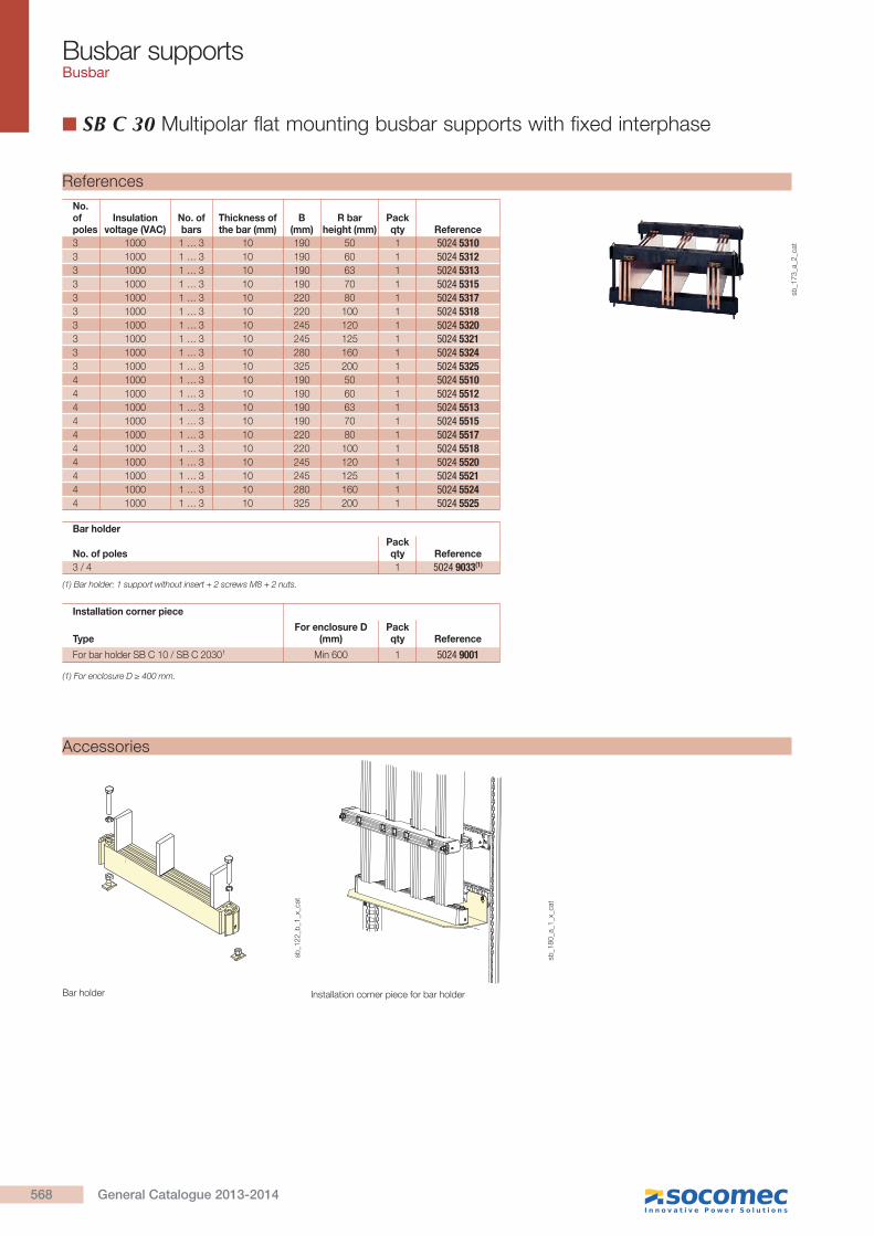
SB C 30 Multipolar flat mounting busbar supports with fixed interphase
References
No. of poles
Insulation voltage (VAC)
No. of bars
Thickness ofthe bar (mm)
B(mm)
R bar height (mm)
Pack qty Reference
3 1000 1 … 3 10 190 50 1 5024 53103 1000 1 … 3 10 190 60 1 5024 53123 1000 1 … 3 10 190 63 1 5024 53133 1000 1 … 3 10 190 70 1 5024 53153 1000 1 … 3 10 220 80 1 5024 53173 1000 1 … 3 10 220 100 1 5024 53183 1000 1 … 3 10 245 120 1 5024 53203 1000 1 … 3 10 245 125 1 5024 53213 1000 1 … 3 10 280 160 1 5024 53243 1000 1 … 3 10 325 200 1 5024 53254 1000 1 … 3 10 190 50 1 5024 55104 1000 1 … 3 10 190 60 1 5024 55124 1000 1 … 3 10 190 63 1 5024 55134 1000 1 … 3 10 190 70 1 5024 55154 1000 1 … 3 10 220 80 1 5024 55174 1000 1 … 3 10 220 100 1 5024 55184 1000 1 … 3 10 245 120 1 5024 55204 1000 1 … 3 10 245 125 1 5024 55214 1000 1 … 3 10 280 160 1 5024 55244 1000 1 … 3 10 325 200 1 5024 5525
Bar holder
No. of polesPack qty Reference
3 / 4 1 5024 9033(1)
Installation corner piece
TypeFor enclosure D
(mm)Pack qty Reference
For bar holder SB C 10 / SB C 20301 Min 600 1 5024 9001
(1) Bar holder: 1 support without insert + 2 screws M8 + 2 nuts.
sb_1
73
_a_2
_cat
Installation corner piece for bar holder
sb_1
22_b
_1_x
_cat
sb_1
80_a
_1_x
_cat
Accessories
Bar holder
568 General Catalogue 2013-2014
Busbar supportsBusbar
Fixed interphase:
3 poles: 185 mm
4 poles: 130 mm
Dimensions
525
560
185
R
40
B
R +
80
sb_1
46_d
_1_x
_cat
525
560
R +
80
130 40
R B
sb_1
57_d
_1_x
_cat
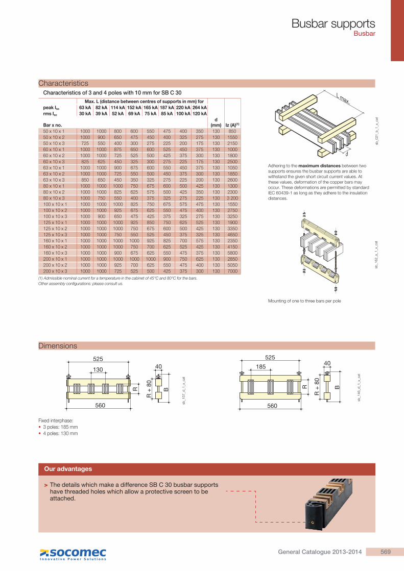
Mounting of one to three bars per pole
L max.
d
sb_0
21
_b_1
_x_c
at
sb_1
62_a
_1_x
_cat
Adhering to the maximum distances between two supports ensures the busbar supports are able to withstand the given short circuit current values. At these values, deformation of the copper bars may occur. These deformations are permitted by standard IEC 60439-1 as long as they adhere to the insulation distances.
Max. L (distance between centres of supports in mm) for
peak Isc 63 kA 82 kA 114 kA 152 kA 165 kA 187 kA 220 kA 264 kA
rms Isc 30 kA 39 kA 52 kA 69 kA 75 kA 85 kA 100 kA 120 kA
Bar x no.d
(mm) Iz (A)(1)
50 x 10 x 1 1000 1000 800 600 550 475 400 350 130 850
50 x 10 x 2 1000 900 650 475 450 400 325 275 130 1550
50 x 10 x 3 725 550 400 300 275 225 200 175 130 2150
60 x 10 x 1 1000 1000 875 650 600 525 450 375 130 1000
60 x 10 x 2 1000 1000 725 525 500 425 375 300 130 1800
60 x 10 x 3 825 625 450 325 300 275 225 175 130 2500
63 x 10 x 1 1000 1000 900 675 600 550 450 375 130 1050
63 x 10 x 2 1000 1000 725 550 500 450 375 300 130 1850
63 x 10 x 3 850 650 450 350 325 275 225 200 130 2600
80 x 10 x 1 1000 1000 1000 750 675 600 500 425 130 1300
80 x 10 x 2 1000 1000 825 625 575 500 425 350 130 2300
80 x 10 x 3 1000 750 550 400 375 325 275 225 130 3 200
100 x 10 x 1 1000 1000 1000 825 750 675 575 475 130 1550
100 x 10 x 2 1000 1000 925 675 625 550 475 400 130 2750
100 x 10 x 3 1000 900 650 475 425 375 325 275 130 3250
125 x 10 x 1 1000 1000 1000 925 850 750 625 525 130 1900
125 x 10 x 2 1000 1000 1000 750 675 600 500 425 130 3350
125 x 10 x 3 1000 1000 750 550 525 450 375 325 130 4650
160 x 10 x 1 1000 1000 1000 1000 925 825 700 575 130 2350
160 x 10 x 2 1000 1000 1000 750 700 625 525 425 130 4150
160 x 10 x 3 1000 1000 900 675 625 550 475 375 130 5800
200 x 10 x 1 1000 1000 1000 1000 1000 900 750 625 130 2850
200 x 10 x 2 1000 1000 925 700 625 550 475 400 130 5050
200 x 10 x 3 1000 1000 725 525 500 425 375 300 130 7000
(1) Admissible nominal current for a temperature in the cabinet of 45°C and 80°C for the bars.Other assembly configurations: please consult us.
Characteristics
Our advantages
> The details which make a difference SB C 30 busbar supports have threaded holes which allow a protective screen to be attached.
Characteristics of 3 and 4 poles with 10 mm for SB C 30
569General Catalogue 2013-2014
Busbar supportsBusbar
References
Description of accessoriesThickness of the bar (mm)
No. of
poles Length Quantity
To be ordered
in multiples of Reference
Slot for 5 mm bars 5 3 6(1) 8 5025 5105Slot for 5 mm bars 5 4 8(1) 8 5025 5105Slot for 10 mm bars 10 3 6(1) 4 5025 5110Slot for 10 mm bars 10 4 8(1) 4 5025 5110Rod kit (bar height 25 to 200 mm)
2(1) 4 5025 5100
380 mm profile 380 2(1) 4 5025 5124480 mm profile 480 2(1) 4 5025 5125580 mm profile 580 2(1) 4 5025 5126780 mm profile 780 2(1) 4 5025 51282 m profile 2000 4 5025 5120Profile for Prisma cabinet(2) 525 1(1) 1 5025 5130
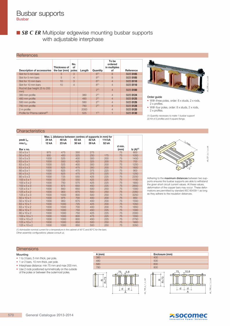
SB C ER Multipolar edgewise mounting busbar supports with adjustable interphase
Order guide
With three poles, order: 6 x studs, 2 x rods, 2 x profiles.
With four poles, order: 8 x studs, 2 x rods, 2 x profiles.
Dimensions
Mounting
1 to 3 bars, 5 mm thick, per pole.
1 or 2 bars, 10 mm thick, per pole.
Interphase distance: min 75 mm and max 200 mm.
Use 2 rods positioned symmetrically on the outside of the poles or between the outermost poles.
A (mm) Enclosure (mm)380 400480 500580 600780 800
A
RR
+73
d d
5.875
sb_1
98_a
_1_x
_cat
dA
RR
+73
d
10.875
sb_1
99_a
_1_x
_cat
Characteristics
Adhering to the maximum distances between two sup-ports ensures the busbar supports are able to withstand the given short circuit current values. At these values, deformation of the copper bars may occur. These defor-mations are permitted by standard IEC 60439-1 as long as they adhere to the insulation distances.
Max. L (distance between centres of supports in mm) forpeak Isc 24 kA 48 kA 63 kA 82 kA 114 kA
rms Isc 12 kA 23 kA 30 kA 39 kA 52 kA
Bar x no.d min. (mm) Iz (A)(1)
50 x 5 x 1 975 475 350 275 75 60050 x 5 x 2 900 450 325 250 175 75 105050 x 5 x 3 1000 525 400 300 200 75 145063 x 5 x 1 1000 550 425 325 200 75 70063 x 5 x 2 1000 525 400 300 200 75 125063 x 5 x 3 1000 625 475 350 200 75 180080 x 5 x 1 1000 625 475 375 225 75 90080 x 5 x 2 1000 625 475 375 225 75 125080 x 5 x 3 1000 725 550 425 225 75 2200100 x 5 x 1 1000 725 550 425 225 75 1100100 x 5 x 2 1000 750 575 425 225 75 1900100 x 5 x 3 1000 875 650 450 225 75 2650125 x 5 x 1 1000 850 650 500 250 75 1300125 x 5 x 2 1000 900 675 500 250 75 2350125 x 5 x 3 1000 1000 800 500 250 75 325050 x 10 x 1 1000 975 700 400 200 75 85050 x 10 x 2 1000 950 675 400 200 75 155063 x 10 x 1 1000 1000 725 425 200 75 105063 x 10 x 2 1000 1000 700 400 200 75 185080 x 10 x 1 1000 1000 750 450 225 75 130080 x 10 x 2 1000 1000 750 425 225 75 2300100 x 10 x 1 1000 1000 800 475 225 75 1550100 x 10 x 2 1000 1000 800 450 225 75 2750125 x 10 x 1 1000 1000 850 500 250 75 1900125 x 10 x 2 1000 1000 850 500 250 75 3350
L max.
d
sb_0
21_b
_1_x
_cat
(1) Admissible nominal current for a temperature in the cabinet of 45°C and 80°C for the bars.Other assembly configurations: please consult us.
(1) Quantity necessary to make 1 busbar support(2) Kit of 2 profiles and 4 square fixings.
sb_2
06
_a_1
_x_c
at
570 General Catalogue 2013-2014
Busbar supportsBusbar
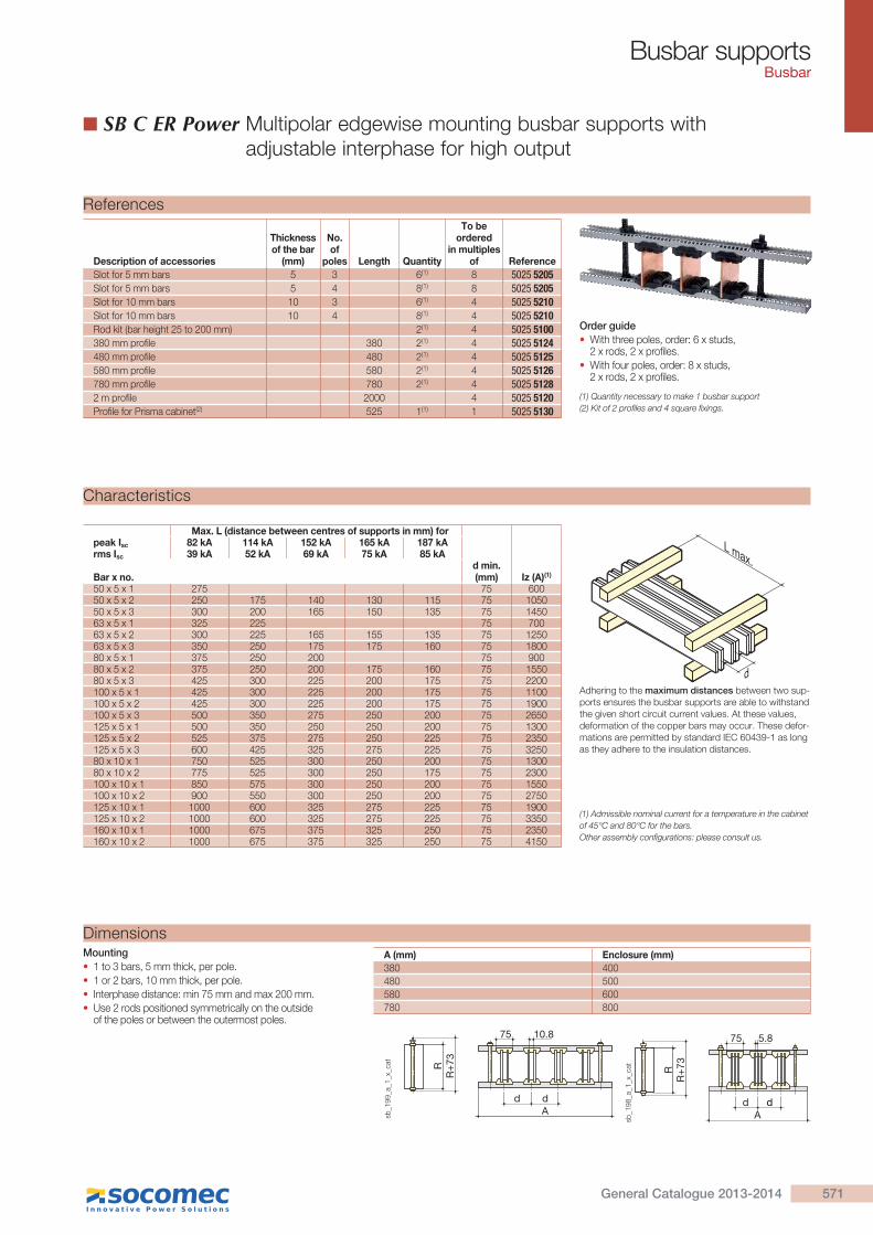
SB C ER Power Multipolar edgewise mounting busbar supports with adjustable interphase for high output
DimensionsMounting
1 to 3 bars, 5 mm thick, per pole.
1 or 2 bars, 10 mm thick, per pole.
Interphase distance: min 75 mm and max 200 mm.
Use 2 rods positioned symmetrically on the outside of the poles or between the outermost poles.
A (mm) Enclosure (mm)
380 400
480 500
580 600
780 800
dA
RR
+73
d
10.875
sb_1
99_a
_1_x
_cat
A
RR
+73
d d
5.875
sb_1
98_a
_1_x
_cat
Characteristics
Adhering to the maximum distances between two sup-ports ensures the busbar supports are able to withstand the given short circuit current values. At these values, deformation of the copper bars may occur. These defor-mations are permitted by standard IEC 60439-1 as long as they adhere to the insulation distances.
Max. L (distance between centres of supports in mm) forpeak Isc 82 kA 114 kA 152 kA 165 kA 187 kArms Isc 39 kA 52 kA 69 kA 75 kA 85 kA
Bar x no.d min. (mm) Iz (A)(1)
50 x 5 x 1 275 75 60050 x 5 x 2 250 175 140 130 115 75 105050 x 5 x 3 300 200 165 150 135 75 145063 x 5 x 1 325 225 75 70063 x 5 x 2 300 225 165 155 135 75 125063 x 5 x 3 350 250 175 175 160 75 180080 x 5 x 1 375 250 200 75 90080 x 5 x 2 375 250 200 175 160 75 155080 x 5 x 3 425 300 225 200 175 75 2200100 x 5 x 1 425 300 225 200 175 75 1100100 x 5 x 2 425 300 225 200 175 75 1900100 x 5 x 3 500 350 275 250 200 75 2650125 x 5 x 1 500 350 250 250 200 75 1300125 x 5 x 2 525 375 275 250 225 75 2350125 x 5 x 3 600 425 325 275 225 75 325080 x 10 x 1 750 525 300 250 200 75 130080 x 10 x 2 775 525 300 250 175 75 2300100 x 10 x 1 850 575 300 250 200 75 1550100 x 10 x 2 900 550 300 250 200 75 2750125 x 10 x 1 1000 600 325 275 225 75 1900125 x 10 x 2 1000 600 325 275 225 75 3350160 x 10 x 1 1000 675 375 325 250 75 2350160 x 10 x 2 1000 675 375 325 250 75 4150
(1) Admissible nominal current for a temperature in the cabinet of 45°C and 80°C for the bars.Other assembly configurations: please consult us.
L max.
d
References
Order guide
With three poles, order: 6 x studs, 2 x rods, 2 x profiles.
With four poles, order: 8 x studs, 2 x rods, 2 x profiles.
Description of accessories
Thickness of the bar
(mm)
No. of
poles Length Quantity
To be ordered
in multiples of Reference
Slot for 5 mm bars 5 3 6(1) 8 5025 5205Slot for 5 mm bars 5 4 8(1) 8 5025 5205Slot for 10 mm bars 10 3 6(1) 4 5025 5210Slot for 10 mm bars 10 4 8(1) 4 5025 5210Rod kit (bar height 25 to 200 mm) 2(1) 4 5025 5100380 mm profile 380 2(1) 4 5025 5124480 mm profile 480 2(1) 4 5025 5125580 mm profile 580 2(1) 4 5025 5126780 mm profile 780 2(1) 4 5025 51282 m profile 2000 4 5025 5120Profile for Prisma cabinet(2) 525 1(1) 1 5025 5130
(1) Quantity necessary to make 1 busbar support(2) Kit of 2 profiles and 4 square fixings.
571General Catalogue 2013-2014
Busbar supportsBusbar
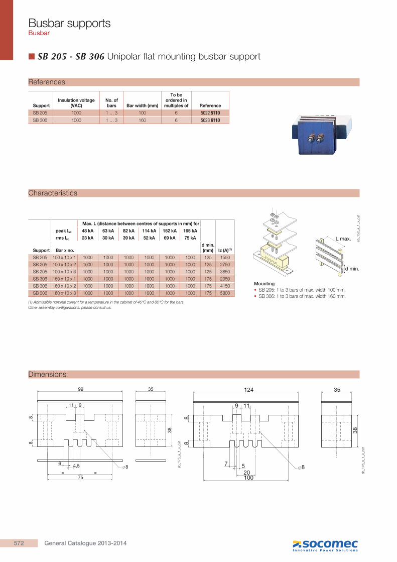
SB 205 - SB 306 Unipolar flat mounting busbar support
L max.
d min.
Mounting
SB 205: 1 to 3 bars of max. width 100 mm.
SB 306: 1 to 3 bars of max. width 160 mm.
Max. L (distance between centres of supports in mm) for
peak Isc 48 kA 63 kA 82 kA 114 kA 152 kA 165 kA
rms Isc 23 kA 30 kA 39 kA 52 kA 69 kA 75 kA
Support Bar x no.d min. (mm) Iz (A)(1)
SB 205 100 x 10 x 1 1000 1000 1000 1000 1000 1000 125 1550
SB 205 100 x 10 x 2 1000 1000 1000 1000 1000 1000 125 2750
SB 205 100 x 10 x 3 1000 1000 1000 1000 1000 1000 125 3850
SB 306 160 x 10 x 1 1000 1000 1000 1000 1000 1000 175 2350
SB 306 160 x 10 x 2 1000 1000 1000 1000 1000 1000 175 4150
SB 306 160 x 10 x 3 1000 1000 1000 1000 1000 1000 175 5800
(1) Admissible nominal current for a temperature in the cabinet of 45°C and 80°C for the bars.Other assembly configurations: please consult us.
sb_1
52_a
_1_x
_cat
Characteristics
99
75= =
6 4,5
35
38
88
8
11 9
sb_1
75_a
_1_x
_cat
124
10020
7 5
35
38
88
8
9 11
sb_1
76_a
_1_x
_cat
Dimensions
SupportInsulation voltage
(VAC)No. of bars Bar width (mm)
To be ordered in
multiples of Reference
SB 205 1000 1 … 3 100 6 5022 5110SB 306 1000 1 … 3 160 6 5023 6110
References
572 General Catalogue 2013-2014
Busbar supportsBusbar
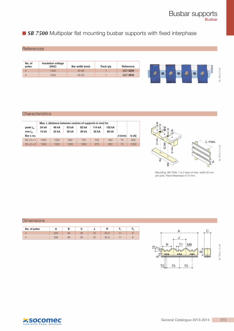
SB 7500 Multipolar flat mounting busbar supports with fixed interphase
L max.
d
Max. L (distance between centres of supports in mm) for
peak Isc 24 kA 48 kA 63 kA 82 kA 114 kA 152 kA
rms Isc 12 kA 23 kA 30 kA 39 kA 52 kA 69 kA
Bar x no. d (mm) Iz (A)
50 x 5 x 1 1000 1000 950 725 525 450 75 600
50 x 5 x 2 1000 1000 1000 1000 975 850 75 1050
Mounting: SB 7500: 1 to 2 bars of max. width 50 mm per pole. Fixed interphase of 75 mm.
sb_1
53_b
_1_x
_cat
Characteristics
No. of poles A B C J R T1 T2
3 220 38 35 75 52.5 11 6
4 295 38 35 75 52.5 11 6
78
13
M8
A
T1
J
R
C
B
75T2 75
sb_1
49_a
_1_x
_cat
Dimensions
No. of poles
Insulation voltage (VAC) Bar width (mm) Pack qty Reference
3 1000 40-50 1 5027 53104 1000 40-50 1 5027 5410
References
sb_1
36
_a_3
_cat
573General Catalogue 2013-2014

Busbar supportsBusbar
SB P 30 Multipolar flat mounting busbar supports with fixed interphase
Mounting
3 poles: 1 to 3 bars of max. width 100 mm per pole, fixed interphase of 185 mm,
4 poles: 1 to 3 bars of max. width 80 mm per pole, fixed interphase of 123 mm.
Max. L (distance between centres of supports in mm) for
peak Isc 63 kA 84 kA 110 kA 143 kA 165 kA 176 kA 187 kA 220 kA
rms Isc 30 kA 40 kA 50 kA 65 kA 75 kA 80 kA 85 kA 100 kA
Bar x no. d (mm) Iz (A)
50 x 5 x 1 1000 1000 800 475 350 300 275 200 185
63 x 5 x 1 1000 1000 800 475 350 300 275 200 185
80 x 5 x 1 1000 1000 800 475 350 300 275 200 185
80 x 5 x 2 1000 1000 800 475 350 300 275 200 185
100 x 5 x 1 1000 1000 775 450 325 300 250 175 185 1100
100 x 5 x 2 1000 1000 775 450 325 300 250 175 185 1900
100 x 5 x 3 1000 1000 775 450 350 300 250 175 185 2650
50 x 10 x 1 1000 1000 800 475 350 300 275 200 185
50 x 10 x 2 1000 1000 800 475 350 300 275 200 185
63 x 10 x 1 1000 1000 800 475 350 300 275 200 185
63 x 10 x 2 1000 1000 800 475 350 300 275 200 185
80 x 10 x 1 1000 1000 800 475 350 300 275 200 185
80 x 10 x 2 1000 1000 800 475 350 300 275 200 185
80 x 10 x 3 1000 1000 800 475 350 300 275 200 185
100 x 10 x 1 1000 1000 775 450 325 300 250 175 185 1550
100 x 10 x 2 1000 1000 775 450 350 300 250 175 185 2750
100 x 10 x 3 1000 1000 775 450 350 300 275 175 185 3850
Max. L (distance between centres of supports in mm) for
peak Isc 63 kA 84 kA 110 kA 143 kA 165 kA 176 kA 187 kA 220 kA
rms Isc 30 kA 40 kA 50 kA 65 kA 75 kA 80 kA 85 kA 100 kA
Bar x no. d (mm) Iz (A)
50 x 5 x 1 1000 950 525 300 225 200 175 130 123 600
63 x 5 x 1 1000 925 525 300 225 200 175 130 123 700
80 x 5 x 1 1000 900 500 300 225 175 175 125 123 900
80 x 5 x 2 1000 900 500 300 225 175 175 125 123 1550
50 x 10 x 1 1000 950 525 300 225 200 175 130 123 850
50 x 10 x 2 1000 975 525 300 225 200 175 135 123 1550
63 x 10 x 1 1000 925 525 300 225 200 175 130 123 1050
63 x 10 x 2 1000 950 525 300 225 200 175 130 123 1850
80 x 10 x 1 1000 900 500 300 225 175 175 125 123 1300
80 x 10 x 2 1000 925 500 300 225 200 175 125 123 2 300
80 x 10 x 3 1000 950 525 300 225 200 175 130 123 3 200
sb_1
60_a
_1_x
_cat
L max.
d
sb_2
00_a
_1_x
_cat
Characteristics
sb_1
54_c
_1_x
_cat
525
185 77,5
36
40185
560525560
4077,5123123123
55 36 55
Dimensions
No. of poles Insulation voltage (VAC) Bar width (mm) Pack qty Reference
3 1000 50-100 1 5023 03104 1000 50-80 1 5023 0410
Mounting bracket
Description of accessories To be ordered in multiples of Reference
2 mounting brackets for SB P 30 1 5024 9002
Bar fixing screws
Description of accessories To be ordered in multiples of Reference
Headless screw for attaching 1 thickness of bar 25 5119 4601Headless screw for attaching 2 thicknesses of bar 25 5119 4602Headless screw for attaching 3 thicknesses of bar 25 5119 4603 sb
_21
0_a
_1_c
at
sb_2
11
_a_1
_cat
References
sb_1
23
_a_3
_cat
d = 123 mm
574 General Catalogue 2013-2014

Busbar supportsBusbar
Hexagonal insulators Unipolar flat mounting busbar support
HeightH (mm) Insert M
DepthD (mm)
DiameterE (mm) Pack qty Reference
20 M4 4 19 1 5031 200420 M6 4 19 1 5031 200625 M6 5 21 1 5031 250630 M6 6 33 1 5031 300630 M8 8 33 1 5031 300835 M6 8 33 1 5031 350635 M8 8 33 1 5031 350835 M10 8 33 1 5031 351040 M8 10 40 1 5031 400840 M10 10 40 1 5031 401045 M8 10 41 1 5031 450845 M10 10 41 1 5031 451050 M8 14 46 1 5031 500850 M10 14 46 1 5031 501050 M12 14 46 1 5031 501260 M10 14 50 1 5031 601065 M10 18 55 1 5031 651070 M12 25 55 1 5031 7012
sb_1
04
_a_2
_cat
Characteristics
E MP
H
sb_1
05_a
_1_x
_cat
HeightH (mm) Insert M
Nominal voltage (V)
AC/DC
Insulation voltage (VAC)50 Hz 1 min Peak
Mechanical characteristics
(daN)Flexion Tention
Max. tightening
torque(Nm)
20(1) M4 500 3000 5500 70 170 9
20 M6 500 3000 5500 100 190 8
25 M6 500 3000 5500 170 370 12
30 M6 1000 6000 11000 200 650 22
30 M8 1000 6000 11000 360 800 40
35 M6 1400 9000 16000 230 720 25
35 M8 1400 9000 16000 380 900 42
35 M10 1400 9000 16000 320 800 44
40 M8 2000 12000 21500 620 1200 50
40 M10 2000 12000 21500 620 1100 60
45 M8 2000 12000 21500 550 1200 55
45 M10 2000 12000 21500 550 1100 65
50 M8 2000 12000 21500 650 1800 60
50 M10 2000 12000 21500 650 1700 70
50 M12 2000 12000 21500 660 13000 130
60 M10 2400 12000 27000 560 1600 85
65 M10 2400 12000 27000 750 1600 90
70 M12 2400 12000 27000 750 1500 135
(1) Admissible nominal current for a temperature in the cabinet of 45°C and 80°C for the bars.Other assembly configurations: please consult us.
Female to female hexagonal insulator
References
575General Catalogue 2013-2014

Busbar supportsBusbar
M
E
P
LH
E
sb_0
58_b
_1_x
_cat
Insulation voltageMechanical
characteristics (daN)
HeightH (mm) Insert M
Nominal voltage (V)
AC/DC(VAC)
50 Hz 1 min Peak Flexion Tention
Max. tightening
torque(Nm)
16 M4 500 3000 5500 100 150 3
16 M5 500 3000 5500 100 150 6
25 M5 500 3000 11000 180 400 6
25 M6 500 3000 11000 180 400 12
35 M8 1400 9000 16000 380 900 42
35 M10 1400 9000 16000 320 800 44
50 M8 2000 12000 21500 650 1800 60
50 M10 2000 12000 21500 650 1700 70
60 M10 2400 12000 27000 560 1600 85
Hexagonal insulator male to female and male to male
Characteristics
HeightH (mm) Insert M
DepthD (mm)
DiameterE (mm)
LengthW (mm) Pack qty Reference
16 M4 5 14 10 1 5038 160416 M5 5 14 10 1 5038 160525 M5 5 20 10 1 5038 250525 M6 5 20 10 1 5038 250635 M8 8 32 15 1 5038 350835 M10 8 32 30 1 5038 351050 M8 14 46 25 1 5038 500850 M10 14 46 30 1 5038 501060 M10 16 50 25 1 5038 6010
sb_1
06
_a_2
_cat
Male to female high withstand insulator
References
Length (mm) ThreadTo be ordered in
multiples of Reference
20 M6 20 5032 200620 M8 20 5032 200825 M6 20 5032 250625 M8 20 5032 250830 M6 20 5032 300630 M8 20 5032 300840 M8 20 5032 400840 M10 20 5032 401050 M12 20 5032 5012
sb_1
21_a
_2_c
at
Headless screw
References
HeightH (mm) Insert M
DiameterE (mm)
LengthW (mm) Pack qty Reference
16 M4 14 10 1 5039 160416 M5 14 10 1 5039 160525 M5 14 10 1 5039 250525 M6 20 10 1 5039 250635 M8 32 15 1 5039 350835 M10 32 30 1 5039 351050 M8 46 25 1 5039 500850 M10 46 30 1 5039 501060 M10 38 25 1 5039 6010
sb_1
07_a
_2_c
at
Male to male high withstand insulator
References
576 General Catalogue 2013-2014
Busbar supportsBusbar
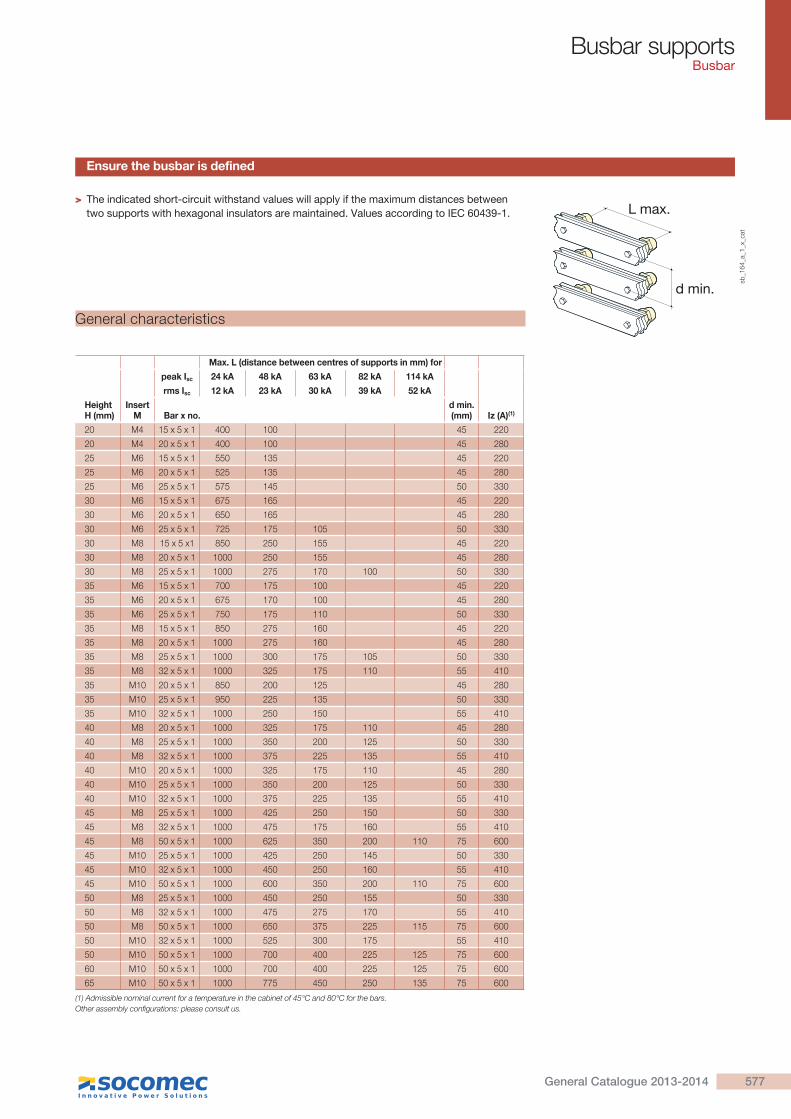
> The indicated short-circuit withstand values will apply if the maximum distances between two supports with hexagonal insulators are maintained. Values according to IEC 60439-1. L max.
d min.
sb_1
64
_a_1
_x_c
at
Max. L (distance between centres of supports in mm) for
peak Isc 24 kA 48 kA 63 kA 82 kA 114 kA
rms Isc 12 kA 23 kA 30 kA 39 kA 52 kA
Height H (mm)
Insert M Bar x no.
d min. (mm) Iz (A)(1)
20 M4 15 x 5 x 1 400 100 45 220
20 M4 20 x 5 x 1 400 100 45 280
25 M6 15 x 5 x 1 550 135 45 220
25 M6 20 x 5 x 1 525 135 45 280
25 M6 25 x 5 x 1 575 145 50 330
30 M6 15 x 5 x 1 675 165 45 220
30 M6 20 x 5 x 1 650 165 45 280
30 M6 25 x 5 x 1 725 175 105 50 330
30 M8 15 x 5 x1 850 250 155 45 220
30 M8 20 x 5 x 1 1000 250 155 45 280
30 M8 25 x 5 x 1 1000 275 170 100 50 330
35 M6 15 x 5 x 1 700 175 100 45 220
35 M6 20 x 5 x 1 675 170 100 45 280
35 M6 25 x 5 x 1 750 175 110 50 330
35 M8 15 x 5 x 1 850 275 160 45 220
35 M8 20 x 5 x 1 1000 275 160 45 280
35 M8 25 x 5 x 1 1000 300 175 105 50 330
35 M8 32 x 5 x 1 1000 325 175 110 55 410
35 M10 20 x 5 x 1 850 200 125 45 280
35 M10 25 x 5 x 1 950 225 135 50 330
35 M10 32 x 5 x 1 1000 250 150 55 410
40 M8 20 x 5 x 1 1000 325 175 110 45 280
40 M8 25 x 5 x 1 1000 350 200 125 50 330
40 M8 32 x 5 x 1 1000 375 225 135 55 410
40 M10 20 x 5 x 1 1000 325 175 110 45 280
40 M10 25 x 5 x 1 1000 350 200 125 50 330
40 M10 32 x 5 x 1 1000 375 225 135 55 410
45 M8 25 x 5 x 1 1000 425 250 150 50 330
45 M8 32 x 5 x 1 1000 475 175 160 55 410
45 M8 50 x 5 x 1 1000 625 350 200 110 75 600
45 M10 25 x 5 x 1 1000 425 250 145 50 330
45 M10 32 x 5 x 1 1000 450 250 160 55 410
45 M10 50 x 5 x 1 1000 600 350 200 110 75 600
50 M8 25 x 5 x 1 1000 450 250 155 50 330
50 M8 32 x 5 x 1 1000 475 275 170 55 410
50 M8 50 x 5 x 1 1000 650 375 225 115 75 600
50 M10 32 x 5 x 1 1000 525 300 175 55 410
50 M10 50 x 5 x 1 1000 700 400 225 125 75 600
60 M10 50 x 5 x 1 1000 700 400 225 125 75 600
65 M10 50 x 5 x 1 1000 775 450 250 135 75 600
(1) Admissible nominal current for a temperature in the cabinet of 45°C and 80°C for the bars. Other assembly configurations: please consult us.
Ensure the busbar is defined
General characteristics
577General Catalogue 2013-2014
Busbar supportsBusbar
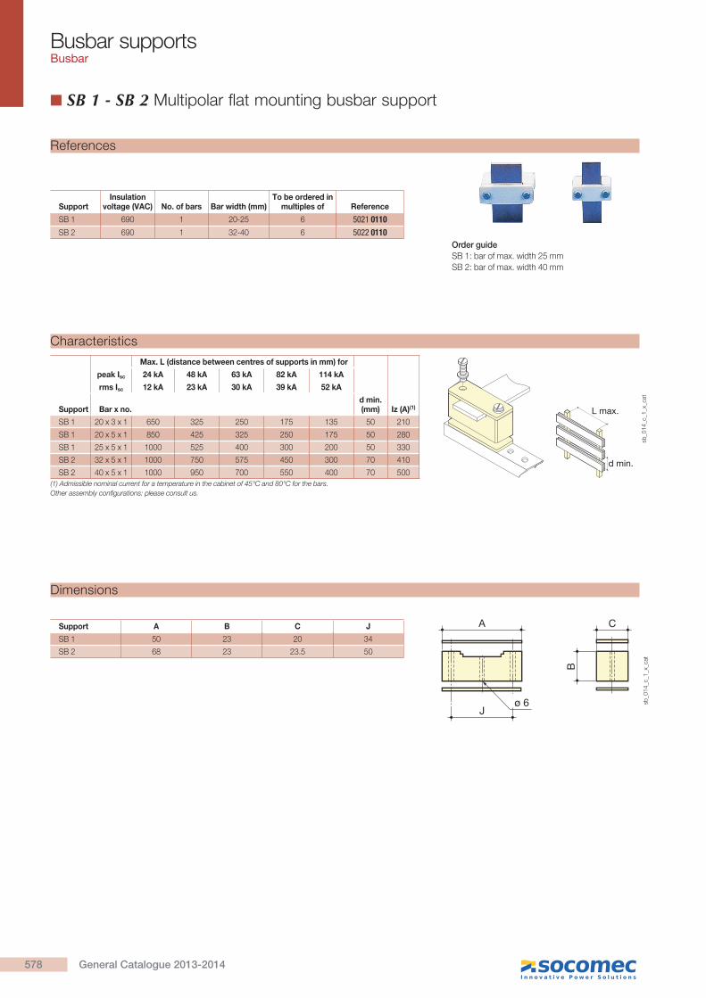
SB 1 - SB 2 Multipolar flat mounting busbar support
Max. L (distance between centres of supports in mm) for
peak Isc 24 kA 48 kA 63 kA 82 kA 114 kA
rms Isc 12 kA 23 kA 30 kA 39 kA 52 kA
Support Bar x no.d min. (mm) Iz (A)(1)
SB 1 20 x 3 x 1 650 325 250 175 135 50 210
SB 1 20 x 5 x 1 850 425 325 250 175 50 280
SB 1 25 x 5 x 1 1000 525 400 300 200 50 330
SB 2 32 x 5 x 1 1000 750 575 450 300 70 410
SB 2 40 x 5 x 1 1000 950 700 550 400 70 500
L max.
d min.
sb_0
14_c
_1_x
_cat
(1) Admissible nominal current for a temperature in the cabinet of 45°C and 80°C for the bars.Other assembly configurations: please consult us.
Characteristics
Support A B C J
SB 1 50 23 20 34
SB 2 68 23 23.5 50
J
A C
B
ø 6 sb_0
14_c
_1_x
_cat
Dimensions
Order guide
SB 1: bar of max. width 25 mm
SB 2: bar of max. width 40 mm
SupportInsulation
voltage (VAC) No. of bars Bar width (mm)To be ordered in
multiples of Reference
SB 1 690 1 20-25 6 5021 0110SB 2 690 1 32-40 6 5022 0110
References
578 General Catalogue 2013-2014

Busbar supportsBusbar
SB 3 Multipolar flat mounting busbar support
Max. L (distance between centres of supports in mm) for
peak Isc 24 kA 48 kA 63 kA 82 kA 114 kA
rms Isc 12 kA 23 kA 30 kA 39 kA 52 kA
Bar x no. d min. (mm) Iz (A)(1)
32 x 5 x 2 1000 1000 925 700 500 70 580
40 x 5 x 2 1000 1000 1000 1000 1000 70 700
50 x 5 x 2 1000 1000 1000 925 675 75 850
63 x 5 x 2 1000 1000 1000 1000 1000 85 1000
sb_0
08_a
_1_x
_cat
L maxi
d mini
sb_0
23_b
_1_f
_cat
(1) Admissible nominal current for a temperature in the cabinet of 45°C and 80°C for the bars.Other assembly configurations: please consult us.
Characteristics
Support A B C J
SB 3 bare 65 32 28 36
SB 3 pre-equipped 65 32 28 36
J
A C
B
ø 8
sb_0
89_b
_1_x
_cat
Dimensions
Order guide
SB 3: 1 to 2 bars of max. width 63 mm.
SupportInsulation
voltage (VAC)No. of bars
Bar width (mm)
To be ordered in multiples of Reference
SB 3 bare 690 1 … 2 32-63 6 5023 0111SB 3 pre-equipped(1) 690 1 … 2 32-63 6 5023 0110
(1) SB3 bare with screws.
References
579General Catalogue 2013-2014
Busbar supportsBusbar
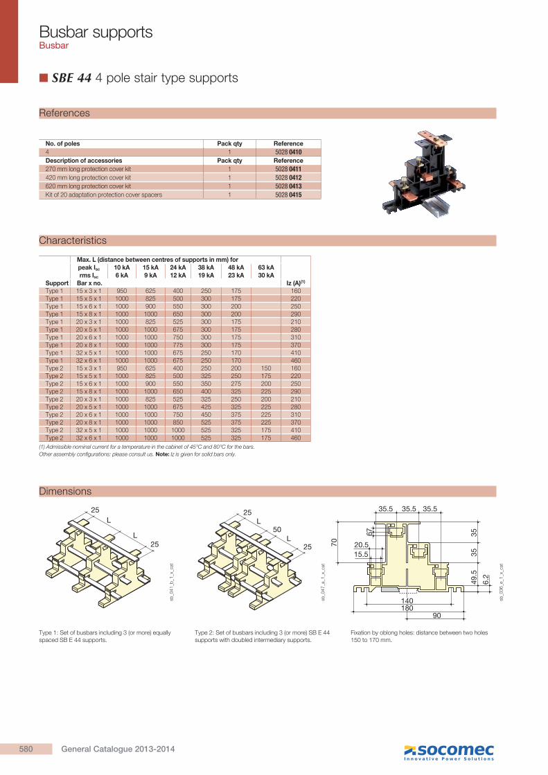
SBE 44 4 pole stair type supports
Fixation by oblong holes: distance between two holes 150 to 170 mm.
Type 1: Set of busbars including 3 (or more) equally spaced SB E 44 supports.
Type 2: Set of busbars including 3 (or more) SB E 44 supports with doubled intermediary supports.
Max. L (distance between centres of supports in mm) forpeak Isc 10 kA 15 kA 24 kA 38 kA 48 kA 63 kArms Isc 6 kA 9 kA 12 kA 19 kA 23 kA 30 kA
Support Bar x no. Iz (A)(1)
Type 1 15 x 3 x 1 950 625 400 250 175 160Type 1 15 x 5 x 1 1000 825 500 300 175 220Type 1 15 x 6 x 1 1000 900 550 300 200 250Type 1 15 x 8 x 1 1000 1000 650 300 200 290Type 1 20 x 3 x 1 1000 825 525 300 175 210Type 1 20 x 5 x 1 1000 1000 675 300 175 280Type 1 20 x 6 x 1 1000 1000 750 300 175 310Type 1 20 x 8 x 1 1000 1000 775 300 175 370Type 1 32 x 5 x 1 1000 1000 675 250 170 410Type 1 32 x 6 x 1 1000 1000 675 250 170 460Type 2 15 x 3 x 1 950 625 400 250 200 150 160Type 2 15 x 5 x 1 1000 825 500 325 250 175 220Type 2 15 x 6 x 1 1000 900 550 350 275 200 250Type 2 15 x 8 x 1 1000 1000 650 400 325 225 290Type 2 20 x 3 x 1 1000 825 525 325 250 200 210Type 2 20 x 5 x 1 1000 1000 675 425 325 225 280Type 2 20 x 6 x 1 1000 1000 750 450 375 225 310Type 2 20 x 8 x 1 1000 1000 850 525 375 225 370Type 2 32 x 5 x 1 1000 1000 1000 525 325 175 410Type 2 32 x 6 x 1 1000 1000 1000 525 325 175 460
(1) Admissible nominal current for a temperature in the cabinet of 45°C and 80°C for the bars.Other assembly configurations: please consult us. Note: Iz is given for solid bars only.
L 25
50
25L
35.5
76
35.5 35.5
70
6.2
3535
49.5
15.520.5
140180
90
L 25
25L
sb_0
41_b
_1_x
_cat
sb_0
36_e
_1_x
_cat
sb_0
47_a
_1_x
_cat
Characteristics
Dimensions
No. of poles Pack qty Reference
4 1 5028 0410Description of accessories Pack qty Reference
270 mm long protection cover kit 1 5028 0411420 mm long protection cover kit 1 5028 0412620 mm long protection cover kit 1 5028 0413Kit of 20 adaptation protection cover spacers 1 5028 0415
References
580 General Catalogue 2013-2014

Busbar supportsBusbar
Max. L (distance between centres of supports in mm) for
peak Isc 10 kA 15 kA 24 kA 48 kA 63 kA
rms Isc 6 kA 9 kA 12 kA 23 kA 30 kA
Bar x no.d min. (mm) Iz (A)
12 x 5 x 1 1000 475 175 60 180
20 x 5 x 1 1000 1000 650 165 60 280
25 x 5 x 1 1000 1000 650 160 60 338
30 x 5 x 1 1000 1000 850 200 120 60 390
25 x 10 x 1 1000 1000 1000 250 150 60 508
30 x 10 x 1 1000 1000 1000 350 200 60 580
No. of poles Insulation voltage (VAC) Bar width (mm)Pack qty Reference
4 1000 20-32 1 5026 0450
Max. L (distance between centres of supports in mm) forpeak Isc 10 kA 15 kA 24 kA 48 kA 63 kA 82 kArms Isc 6 kA 9 kA 12 kA 23 kA 30 kA 39 kA
Bar x no.d min. (mm) Iz (A)
20 x 5 x 1 1000 1000 800 350 200 125 50 28025 x 5 x 1 1000 1000 1000 350 200 125 50 33032 x 5 x 1 1000 1000 1000 350 200 120 50 39025 x 10 x 1 1000 1000 1000 350 200 125 50 50030 x 10 x 1 1000 1000 1000 350 200 120 50 58032 x 10 x 1 1000 1000 1000 350 200 120 50 610
SB P 44: 1 bar with a thickness of 5 or 10 mm, width 20, 25, 30 or 32 mm.
Note: protection cover not supplied.sb
_165_b
_1_x
_cat
sb_1
59
_a_1
_x_c
at
SB P 10 Multipolar flat mounting busbar supports with fixed interphase
5050 50 1275
.5
245
150
114
53.5
sb_1
47_b
_1_x
_cat
SB P 44 4-pole flat mounting busbar support with fixed interphase, for mounting tilted bars
Characteristics
No. of poles Insulation voltage (VAC) Bar width (mm)Pack qty Reference
4 690 12-30 1 5026 0460SB P 10: 1 bar with a thickness of 5 or 10 mm, width 12, 20, 25 or 30 mm.
References
Characteristics
References
sb_1
44_a
_1_x
_cat
15242 22
1742
62.5 67.5 54
Dimensions
Dimensions
581General Catalogue 2013-2014