snap telescope m.lampton f, c.akerlof b, g.aldering a, r.amanullah c, p.astier d, e.barrelet d,...
TRANSCRIPT

SNAP TelescopeSNAP Telescope
M.Lamptonf, C.Akerlof b, G.Alderinga, R.Amanullahc, P.Astierd, E.Barreletd, C.Bebeka, L.Bergstromc, J.Bercovitza, G.Bernsteine, M.Besterf, A.Bonissentg, C.Bowerh, W.Carithersa,
E.Comminsf, C.Daya, S.Deustuai, R.DiGennaroa, A.Ealetg, R.Ellisj, M.Erikssonc, A.Fruchterk, J-F.Genatd, G.Goldhaberf, A.Goobarc, D.Grooma, S.Harrisf, P.Harveyf, H.Heetderksf, S.Hollanda, D.Hutererl, A.Karcher a, A.Kima, W.Kolbea, B.Kriegera,
R.Lafevera, J.Lamoureuxf, M.Levia, D.Levinb, E.Lindera, S.Lokena, R.Malinam, R.Masseyn, T.McKayb, S.McKeeb, R.Miquela, E.Mortsellc, N.Mostekh, S.Mufsonh, J.Musserh,P.Nugenta, H.Oluseyia, R.Paind, N.Palaioa, D.Pankowf, S.Perlmuttera, R.Prattf, E.Prietom, A.Refregiern,
J.Rhodeso, K.Robinsona, N.Roea, M.Shollf, M.Schubnellb, G.Smadjap, G.Smootf, A.Spadaforaa, G.Tarleb, A.Tomaschb, H.von der Lippea, R.Vincentd, J-P.Waldera and
G.Wanga
a Lawrence Berkeley National Laboratory, Berkeley CA, USA, b University of Michigan, Ann Arbor MI, USA,c University of Stockholm, Stockholm, Sweden, d CNRS/IN2P3/LPNHE, Paris, France,
e University of Pennsylvania, Philadelphia PA, USA, f University of California, Berkeley CA, USA, g CNRS/IN2P3/CPPM, Marseille, France, h Indiana University, Bloomington IN, USA,
i American Astronomical Society, Washington DC, USA, j California Institute of Technology, Pasadena CA, USA,k Space Telescope Science Institute, Baltimore MD, USA, l Case Western Reserve University, Cleveland OH, USA,
m CNRS/INSU/LAM, Marseille, France, n Cambridge University, Cambridge, UK,o NASA Goddard Space Flight Center, Greenbelt MD, USA, p CNRS/IN2P3/INPL, Lyon, France

2
Science Driven RequirementsScience Driven Requirements
• Light Gathering Power — must measure SNe 4 magnitudes fainter than 26 magnitude peak— want SNR of 30:1 at peak brightness, aggregate exposure fit— presence of zodiacal light foreground radiation— time-on-target limited by revisit rate & number of fields— spectroscopy demands comparable time-on-target— requires geometric diameter ~ 2 meters
• Angular resolution— signal to noise ratio is driver— diffraction limit is an obvious bound— Airy disk at one micron wavelength is 0.12 arcseconds FWHM— need to match this to pixel size of VIS and NIR detectors
• Field of View— determined by required supernova discovery rate— volume of space is proportional to field of view— one degree field of view will deliver the requisite discovery rate
• Wavelength Coverage— 0.35 to 1.7 microns requires all-reflector optical train
3
Wide Field TelescopesWide Field Telescopes
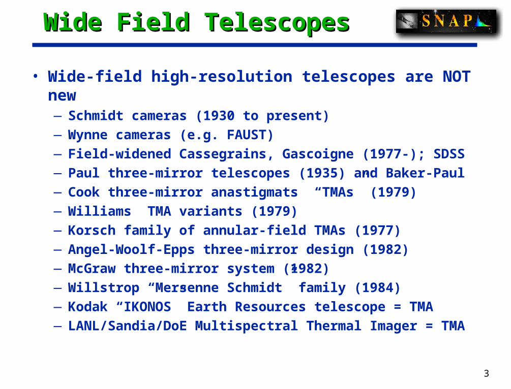
• Wide-field high-resolution telescopes are NOT new—Schmidt cameras (1930 to present)
—Wynne cameras (e.g. FAUST)
—Field-widened Cassegrains, Gascoigne (1977-); SDSS
—Paul three-mirror telescopes (1935) and Baker-Paul
—Cook three-mirror anastigmats “TMAs” (1979)
—Williams TMA variants (1979)
—Korsch family of annular-field TMAs (1977)
—Angel-Woolf-Epps three-mirror design (1982)
—McGraw three-mirror system (1982)
—Willstrop “Mersenne Schmidt” family (1984)
—Kodak “IKONOS” Earth Resources telescope = TMA
—LANL/Sandia/DoE Multispectral Thermal Imager = TMA

4
Baseline ConfigurationBaseline Configuration
• Prolate ellipsoid concave primary mirror
• Hyperbolic convex secondary mirror
• Flat folding mirror with central hole
• Prolate ellipsoid concave tertiary mirror
• Delivers < 0.06 arcsecond FWHM geometrical blur over annular field 1.37 sqdeg
• Flat focal surface
• Adapts to focal lengths 15
meters through 30 meters;
baseline=21.66m
• Provides side-mounted
detector location for best
detector cooling
* Telephoto advantage = 7

5
Baseline CharacteristicsBaseline Characteristics
• Aperture: 2 meters• Annular Field of View: ~1 sq deg• Wavelength Range: 0.35 to 1.7 microns• Strehl: >90% at 1.0 microns• WFE: <50 nm RMS• Focal surface: flat• EFL: 21.66 meters, f/11• Stray light: << Zodiacal foreground
m0.5at 93N
:field limited-ndiffractio huge theis here new isWhat
Elementsresolution Eblurndiffractio
viewoffield

6
Optical PrescriptionOptical Prescription
Table 1: Optical Surfaces and LocationsDiameter,meters
Central hole,meters
Curvature,recip meters
Asphericity Xlocation,meters
Zlocation,meters
Primary 2.00 0.5 -0.2037466 -0.9811128 0 0Secondary 0.45 none -0.9099607 -1.847493 0 -2.00Folding flat 0.66 x 0.45 0.19 x 0.12 0 0 0 +0.91Tertiary 0.68 none -0.7112388 -0.599000 -0.87 +0.91Focal plane 0.567 0.258 0 0 +0.9 +0.91

7
Optical ConfigurationOptical Configuration
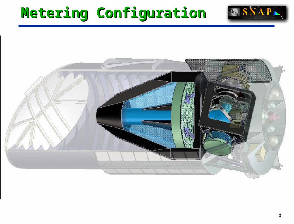
Telescope is a three-mirror anastigmat
2.0 meter aperture
1.37 square degree field
Lightweight primary mirror
Low-expansion materials
Optics kept near 290K
Transverse rear axis
Side Gigacam location
passive detector cooling
combines Si & HgCdTe detectors
Spectrometers share Gigacam focal plane
Few moving parts in payload
two-blade shutter for Gigacam
focussers/adjusters at secondary & tertiary
8
Metering ConfigurationMetering Configuration

9
Payload LayoutPayload Layout
Main Baffle Assembly
Door Assembly
Solar Array, ‘Sun side’
Secondary MirrorHexapodBonnet
Secondary Metering structure
Primary Mirror
Optical Bench
Instrument Metering Structure
Tertiary Mirror
Fold-Flat Mirror
Spacecraft
Shutter
Instrument Bay
Instrument Radiator
Solar Array, ‘Dark side’
Hi Gain Antenna
Solid-state recorders
ACSCD & HCommPowerData
CCD detectorsNIR detectorsSpectrographFocal Plane guiders Cryo/Particle shield

10
Payload LayoutPayload Layout

11
Focal plane conceptFocal plane concept
• Coalesce all sensors at one focal plane.— Imager sensors on the front.
• 36 HgCdTe 2kx2k 18 m• 36 CCD 3.5kx3.5k 10.5 m
— Filters• 1 of 3 per HgCdTe• 4 of 6 per CCD
— Spectrograph on the back with access ports through the focal plane.
• Common 140K operating temperature.
• Dedicated CCDs for guiding from the focal plane.
• Exposure times of 300 s with four/eight exposures in CCDs/HgCdTe.
• 20 s readout slow enough for CCD noise and 4 post exposure and 4 pre exposure reads of HgCdTe.
rin=6.0 mrad; rout=13.0 mradrin=129.120 mm; rout=283.564 mm
12
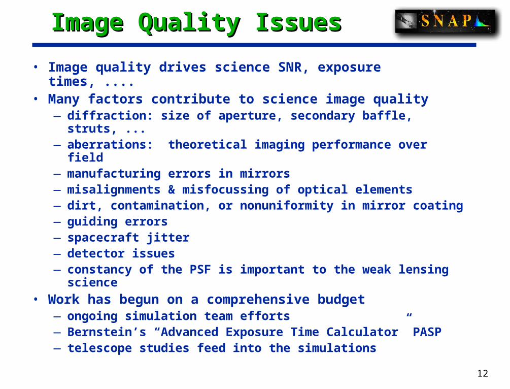
Image Quality IssuesImage Quality Issues
• Image quality drives science SNR, exposure times, ....• Many factors contribute to science image quality
— diffraction: size of aperture, secondary baffle, struts, ...— aberrations: theoretical imaging performance over field— manufacturing errors in mirrors— misalignments & misfocussing of optical elements— dirt, contamination, or nonuniformity in mirror coating — guiding errors— spacecraft jitter— detector issues— constancy of the PSF is important to the weak lensing science
• Work has begun on a comprehensive budget— ongoing simulation team efforts— Bernstein’s “Advanced Exposure Time Calculator” PASP— telescope studies feed into the simulations

13
Example WFE BudgetExample WFE Budget
Primary figure 33 nmSecondary position 5 nm zeroable by telecommandSecondary orientation 5 nm zeroable by telecommandSecondary figure 10 nmFolding flat position 5 nmFolding flat orientation 5 nmFolding flat figure 10 nmTertiary position 5 nm zeroable by telecommandTertiary orientation 5 nm zeroable by telecommandTertiary figure 10 nmDetector position 10 nmDetector orientation 10 nmDetector flatness 10 nmManager's reserve 15 nm---------------------------------------------------------------------TOTAL root sum square 43 nm
Corresponding Strehl = 83% at 0.633um, or 93% at 1.0um

14
Ray Trace ExamplesRay Trace Examples
TMA62/TMA63 configuration TMA62/TMA63 configuration Airy-disk zero at one micron wavelength
26 microns diam=0.244arcsec
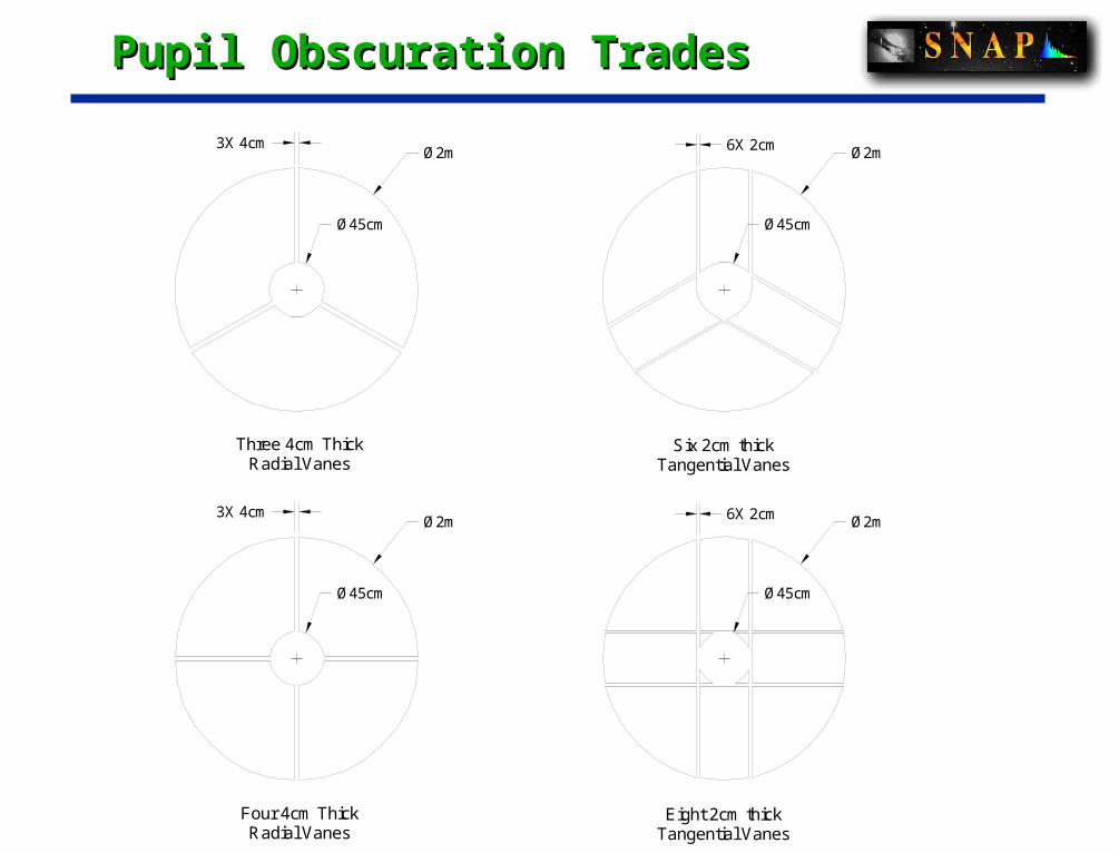
Pupil Obscuration TradesPupil Obscuration Trades
Three 4cm ThickRadial Vanes
Six 2cm thickTangential Vanes
Ø2m
Ø45cm
3X 4cm
Ø45cm
Ø2m6X 2cm
Ø2m
Radial VanesFour 4cm Thick
Ø45cm
3X 4cmØ2m
Ø45cm
Tangential VanesEight 2cm thick
6X 2cm

16
Circular 2m aperture
central 0.7m obscuration
Three legs, 50mm x 1meter
Diffraction

17
Stray Light TradesStray Light Trades
• Principle: keep total stray light FAR BELOW natural Zodi• R.O.M. assessment gives...
— Natural Zodi (G.Aldering) = 1 photon/pixel/sec/micron— Starlight+Zodi scattered off primary mirror = 0.002— Starlight+Zodi scattered off support spider < 0.001— Sunlight scattered off forward outer baffle edge = 2E-5 — Earthlight scattered off forward outer baffle inner surface =
0.02— Total stray = 0.02 photon/pixel/sec/micron
• Long outer baffle is clearly preferred— limit is launch fairing and S/C envelope
• We will be starting detailed stray light assessment in 2003• Our intension is to track hardware & ops changes as they occur,
allowing a “system engineering management” of stray light.

18
Telescope Technology RoadmapTelescope Technology Roadmap
• Existing technologies are suitable for SNAP Optical Telescope Assembly• New materials, processes, test & evaluation methods are unnecessary• Mirror materials
— science driver: *stable* figure to guarantee constant focus and PSF— Corning ULE glass: extensive NRO flight history; lightweight— Schott Zerodur glass/ceramic composite: lower cost, widely used in
ground based astronomical telescopes; huge industrial base— fused silica also a possibility, but CTE issues
• Metering structure materials— science driver: *stable* structure for constant focus and PSF— M55J carbon fiber + cyanate ester resin; epoxy adhesive bonds— full report in Pankow presentation
• Mirror finishing technology— conventional grind/polish/figure using abrasives— ion-beam figuring available from two vendors
• Mirror surface metrology— same as other space telescopes, e.g. cassegrains— standard interferometer setups will do the job for SNAP

19
Mirror Materials TradeMirror Materials Trade
• Corning ULE ultra-low expansion glass— extremely low CTE: 20-50 parts per billion per dec C
— face sheets bonded to honeycomb core
— achieves 85-90% lightweight; anticipate 200kg primary
— extensive manufacturing & test history
— attractive for its high natural resonance frequencies, low sag
— eases mass margin for entire mission
• Fused Silica— large supplier base
— extensive manufacturing and test history
— CTE issue is a potential problem
• Schott Zerodur glass/ceramic material— extremely low CTE: 20-50 parts per billion per deg C
— solid blank, weight relieved by milling backside
— achieves 70-85% lightweight; anticipate 250kg primary
— extensive manufacturing & test history

20
Trade Studies Summary Trade Studies Summary
• Trade Studies worked during Pre-R&D Phase— Optical configuration: >>TMA— Warm optics vs cold optics: >>warm— integrated sensor array vs separated: >>integrated
• Trade Studies continuing through R&D Phase— Exact aperture: cost & schedule vs aperture— Wavefront error: cost vs performance
• focal length: is 21.66m the best choice?• pupil obsuration, diffraction, stray light...
— Primary mirror thickness, stiffness, mass trade• resonance freqs, sag under 1G testing, ...
— Protoflight vs Prototype + Flight metering structures— Vendor-dependent issues
• mirror material: ULE? FS? Zerodur?• test: gravity unloading scheme• test: full aperture vs partial aperture
21
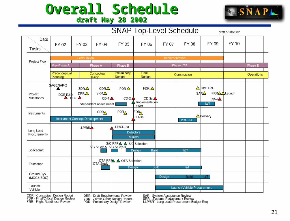
Overall ScheduleOverall Scheduledraft May 28 2002draft May 28 2002
22
ConclusionsConclusions
• Baseline Requirements—Far less demanding than HST: we are NIR not NUV
• Baseline Design—annular field three-mirror anastigmat
• Working towards a biddable requirements document—vendor participation in 2003-2004
• Schedule risks: OTA is a long lead item!• No new technology• Budgets and Plans
—tolerances—stray light—fab plan—test plan