simple metal detector
TRANSCRIPT

Metal Detector Sensor
Rangkaian Metal Detector Sensor Sangat bermanfaat bagi pencegahan/ deteksi dini terhadap ancaman bom atau tindak kejahatan seseorang yang membawa barang berbahaya senjata tajam ,atau senjata berapi
Rangkaian Metal Detector Sensor ini berfungsi untuk mendeteksi adanya metal atau logam. Metal Detector Sensor ini sangat bagus diaplikasikan di sebuah Hotel, Area Parkir, Airport, dan lain-lain.
Simple Metal Detector
Labels: circuits >> Detector >> schematic >> sensors
It's a simple metal detector design that has the quite good characteristics. the principle of operation which one differs from the classic schemes (BFO, transmit-receive known as "two-boxes" metal detector, inductive).
The dynamic mode is used to find targets in interference environment. There is known from theory of signal filtration that if signal shape is determined we can construct optimal filter - the best one for extracting the signal with maximum signal/noise ratio. This filter is known as optimal matched filter. In our device we realized digital optimal matched filter as part of microcontroller software. The filter parameters are optimized for effective ferro- and nonferro targets detection on 0.5-1.0 m/s velocity of sensor.
Features of the Metal Detector:Power supply .............................4.5-6V; DC consumption .......................15 mA; Indication ...................................sound + 8 LEDs; Modes ........................................static or dynamic; Discrimination.............................ferro/non-ferro.

Read more: http://sensors.circuitlab.org/2012/04/simple-metal-detector.html#ixzz23f8MRoxm
Switches controled (versions V1.9 and V2.0 of firmware):S0: reset device;S1: reserved;S2: on - threshold hight, off - threshold low;S3: measuring time on - 30ms, off - 120ms;S4: selftuning on/off (in dynamic mode only);S5: mode on - static, off - dynamic.
Read more: http://sensors.circuitlab.org/2012/04/simple-metal-detector.html#ixzz23f8pCyyo


Metal Detector Coil Design
Approx. 100 curls 200 mm in diameter. Cupper wire in isolation 0,35 mm diameter
Read more: http://sensors.circuitlab.org/2012/04/simple-metal-detector.html#ixzz23f9USWIG
How a Metal Detector WorksAn overview and in-depth article on how Metal Detectors work.
OVERVIEW(By Michael W. Davidson)
The operation of metal detectors is based upon the principles of electromagnetic induction. Metal detectors contain one or more inductor coils that are used to interact with metallic elements on the ground. The single-coil detector illustrated below is a simplified version of one used in a real metal
detector.
A pulsing current is applied to the coil, which then induces a magnetic field shown in blue. When the magnetic field of the coil moves across metal, such as the coin in this illustration, the field induces
electric currents (called eddy currents) in the coin. The eddy currents induce their own magnetic field, shown in red, which generates an opposite current in the coil, which induces a signal indicating the
presence of metal.

MORE ID-DEPTH INFORMATION ON HOW A METAL DETECTOR WORKS
(By Mark Rowan & William Lahr)
Metal detectors are fascination machines. Many of the people who use them are just as enthusiastic about extolling the virtues of their favorite metal detector as they are about setting off in search of buried treasure. Those of us who design and build these instruments for a living listen carefully when one of our customers talks about his or her experience in the field, because this is the primary means by which we determine how well we are doing our jobs, and what sort of things we need to do better. Sometimes though, communication is difficult. Almost as though we and our customers speak different languages. Which in a sense, we do. The purpose of this page is to try to narrow that communication gap a little. And, to resolve some of that "typical curiosity" metal detector operators have regarding what is going on inside their instruments.
Is it necessary to know how a metal detector works in order to use it effectively? Absolutely not. Will knowing how it works help someone to use it more effectively in the future? Quite possibly yes, but only with persistence and practice. The best metal detector available is still only as good as the person using it.
VLF (Very Low Frequency) Transmitter & Receiver
Transmitter
Inside the metal detector's loop (sometimes called a search head, coil, antenna, etc.) is a coil of wire called the transmit coil. Electronic current is driven through the coil to create an electromagnetic field. The direction of the current flow is reversed several thousand times every second; the transmit frequency "operating frequency" refers to the number of times per second that the current flow goes from clockwise to counterclockwise and back to clockwise again.
When the current flows in a given direction, a magnetic field is produced whose polarity (like the north and south poles of a magnet) points into the ground; when the current flow is reversed, the field's polarity points out of the ground. Any metallic (or other electrically conductive) object which happens to be nearby will have a flow of current induced inside of it by the influence of the changing magnetic field, in much the same way that an electric generator produces electricity by moving a coil of wire inside a fixed magnetic field. This current flow
inside a metal object in turn produces its own magnetic field, with a polarity that tends to be pointed opposite to the transmit field.
Receiver
A second coil of wire inside the loop, the receive coil, is arranged (by a variety of methods) so that nearly all of the current that would ordinarily flow in it due to the influence of the transmitted field is cancelled out. Therefore, the field produced by the currents flowing in the nearby metal object will cause currents to flow in the receive coil which may be amplified and processed by the metal detector's electronics without being swamped by currents resulting from the much stronger transmitted field.
The resulting received signal will usually appear delayed when compared to the transmitted signal. This delay is due to the tendency of conductors to impede the flow of current (resistance) and to impede changes in the flow of current (inductance). We call this apparent delay "phase shift". The largest phase shift will occur for metal objects which are primarily inductive; large, thick objects made from excellent conductors like gold, silver, and copper. Smaller phase shifts are typical for objects which are primarily resistive; smaller, thinner objects, or those composed of less conductive materials.
Some materials which conduct poorly or not at all can also cause a strong signal to be picked up by the receiver. We call these materials "ferromagnetic". Ferromagnetic substances tend to become magnetized when placed in a field like a paper clip which becomes temporarily magnetized when picked up with a bar magnet. The received signal shows little if any phase shift. Most soils and sands contain small grains of iron-bearing minerals which causes them to appear largely ferromagnetic to the metal detector. Cast iron (square nails) and steel objects (bottle caps) exhibit both electrical and ferromagnetic properties.
It should be pointed out that this discussion describes an "Induction Balance" metal detector, sometimes referred to as "VLF" Very Low Frequency (below 30kHz). This is the most popular technology at the present time, and includes the "LF" Low Frequency (30 to 300kHz) instruments made for prospecting.
Discrimination
Since the signal received from any given metal object exhibits its own characteristic phase shift, it is possible to classify different types of objects and distinguish between them. For example, a silver dime causes a much larger phase shift than an aluminum pull-tab does, so a metal detector can be set to sound off on a dime yet remain quiet on the pull-tab, and/or show the identification of the target on a display or meter. This process of distinguishing between metal targets is called "discrimination". The simplest form of discrimination allows a metal

detector to respond with an audio output when passed over a target whose phase shift exceeds a certain (usually adjustable) amount. Unfortunately, with this type of discriminator the instrument will not respond to some coins and most jewelry if the discrimination is adjusted high enough to reject common aluminum trash for example pull-tabs and screw-caps.
A more useful scheme is what is called "Notch Discrimination". With this type of system, a notch in the discriminate response allows the metal detector to respond to targets within a certain range (such as the nickel/ring range) while still rejecting targets above that range (pull-tabs, screw-caps) as well as below it (iron, foil). The more sophisticated notch metal detectors allow for each of several ranges to be set for either accept or reject responses. White's Spectrum XLT for example, provides 191 individually programmable notches.
A metal detector may provide a numeric readout, meter indication, or other display mechanism which shows the target's likely identity. We refer to this feature as a Visual Discrimination Indicator, or V.D.I. Metal Detectors with this capability have the advantage of allowing the operator to make informed decisions about which targets they choose to dig rather than relying solely on the instruments audio discriminator to do all the work. Most, if not all, V.D.I. metal detectors are also equipped with audio discriminators.
Metal detectors can distinguish metal objects from each other based on the ratio of their inductance to their resistivity. This ratio gives rise to a predictable delay in the receive signal at a given frequency. An electronic circuit called a phase demodulator can measure this delay. In order to separate two signals, such as the ground component and the target component of the receive signal, as well as to determine the likely identity of the target, we use two such phase demodulators whose peak response is separated from each other by one fourth of the transmitter period, or ninety degrees. We call these two channels "X" and "Y". A third demodulated signal, we call "G", can be adjusted so that its response to any signal with a fixed phase relationship to the transmitter (such as the ground) can be reduced to zero regardless of the strength of the signal.
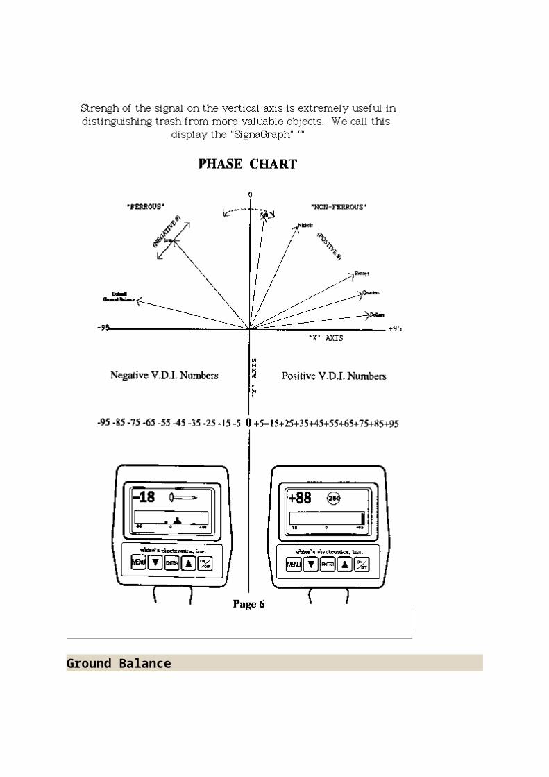
Some metal detectors use a microprocessor to monitor these three channels, determine the targets's likely identity, and assigning it a number based on the ratio of the "X" and "Y" readings, whenever the "G" reading exceeds a predetermined value. We can find this ratio with a resolution of better than 500 to 1 over the full range from ferrite to pure silver. Iron targets are orientation sensitive; therefore as the loop is moved above them, the calculated numerical value may change dramatically. A graphic display showing this numerical value on the horizontal axis and the strength of the signal on the vertical axis is extremely useful in distinguishing trash from more valuable objects. We call this display the "SignaGraph" (TM).
Ground Balance

As previously mentioned, most sands and soils contain some amount of iron. They may also have conductive properties due to the presence of salts dissolved in the ground water. The result is that a signal is received by the metal detector due to the ground itself which may be thousands of times stronger than the signal resulting from small metal objects buried at modest depths. Fortunately, the phase shift caused by the ground tends to remain fairly constant over a limited area. It is possible to arrange things inside the metal detector so that even if the strength of the ground signal changes dramatically--such as when the loop is raised and lowered, or when it passes over a mound or hole--the metal detector's output remains constant. Such a metal detector is said to be "ground balanced". Accurate ground balance makes it possible to "pinpoint" the location of the targets with a good deal of precision as well as to estimate the depth of the targets in the ground. If you choose to search in a non-discriminate, or "all-metal" mode, accurate ground balance is essential.
The simplest form of ground balance consists of a control knob which the operator adjusts while raising and lowering the loop until good balance is achieved. Although this method can be quite effective, it can also be tedious, and some people find it to be difficult or confusing. More advanced metal detectors will perform ground balance automatically, typically by a two-step sequence in which the metal detector is balanced with the loop raised, then balanced once more with the loop lowered to the ground. The most sophisticated ground balance metal detectors will gradually adjust themselves as changes in the composition of the ground occur. We refer to this as "Tracking Ground Balance". A good tracking metal detector allows you to balance once, then hunt for the rest of the day without having to balance again. A word to the wise - many metal detectors which are advertised as having "automatic" or "Tracking" ground balance are actually factory preset to a fixed balance point. Its a little like welding your car's accelerator halfway to the floor and calling it "cruise control".
Motion/Non-Motion Modes
Athough the ground signal may be much stronger than the target signal, the ground signal tends to remain the same, or change very slowly, as the loop is moved. The signal from the target, on the other hand, will rise quickly to a peak and then subside when the loop is swept over it. This opens up the possibility of using techniques to separate ground from target signals by looking at the rate of change of the receive signal rather than looking at the receive signal itself. Metal detector modes of operation which rely on this principle are called, not surprisingly, "Motion" modes. The most important example is a mode called "Motion Discrimination". If we wish to isolate the target signal well enough to determine the target's identity, the ground balance alone is not enough. We need to look at the target from a couple of different perspectives, sort of like the way distances can by measured by triangulation if you have more than one viewpoint. We can only be
ground balanced from one particular "viewpoint"; the other will contain some combination of target and ground signal. Fortunately, we can use the motion technique to minimize the effect of the remaining ground signal. At the present time, all discriminating and V.D.I. metal detectors require loop motion to be effective. This turns out not to be much of a penalty in practice since you have to move the loop anyway in order to cover any ground.
Once you have located a target in the motion discrimination mode, you will probably want to more precisely locate it for easy recovery. If your metal detector is equipped with a depth meter, you will also want to measure the target's depth. "Pinpoint" locating and depth measurement are done in what is called the "All Metal" mode. Since discrimination is not required to perform these functions, loop motion is not usually required -- except for that motion required to get the loop over the center of the target. More precisely, the speed at which you move the loop is not important. The All Metal mode (also sometimes called the "Normal" mode, or "D.C." mode) is therefore called a "Non Motion" mode.
There are a few potential points of confusion here. Some metal detectors are equipped with a feature called "Self Adjusting Threshold", or S.A.T., which gradually increases or decreases the audio output in an attempt to maintain a quiet but audible "threshold" sound. This helps to smooth out audio changes caused by the ground or inadequate ground balance. S.A.T. may be very rapid or very slow depending on the metal detector and how it's adjusted, but strictly speaking, S.A.T. implies a motion mode of operation. This is why you will hear certain metal detectors referred to as having a "True Non Motion" mode; meaning, of course, an All Metal mode without S.A.T. Another sometimes confusing thing is that some discriminators allow for adjustment down to the point that the discriminator responds to all metals -- in other words, it's a discriminator that doesn't discriminate. This is something very different, however, than the All Metal mode previously described. For this reason we often refer to it as a "Zero Disc" mode.
Microprocessor Control
The microprocessor is a complex electronic circuit which can perform all of the logic, arithmetic, and control functions necessary to build a computer. A sequence of stored instructions called a "Program" is performed by the microprocessor, one at a time, at a speed which can be as high as several million times every second.
The use of microprocessors in modern metal detectors has opened up possibilities which were undreamed of just a few years ago. In the past, adding new and useful features to a metal detector meant additional control knobs and switches. There were obvious limits to this approach; at some point size, cost, and operator confusion got out of hand. With a microprocessor, a liquid crystal display, and a simple keypad the problem is solved. A virtually unlimited number of features can be added without adding any additional hardware. These features can be arranged
by a system of "Menus", so that anybody who can follow the prompts on the display can easily find the control they're after and adjust it to their liking. In this way, a single metal detector can be set up for just about any application, or to suit anyone's personal preference.
You might think that this sounds a little complicated -- what if you don't want to be bothered with making all of those adjustments? Here's the real beauty of microprocessor control; you don't have to. Each control can be set to a typically useful position by the microprocessor each time you turn the machine on so the beginner or casual user never has to know that all those advanced features are there. Or better yet, you can select your preference from the menu -- coin hunting, prospecting, relic hunting, etc. -- and the microprocessor will make all of the adjustments for you choosing settings that have been proven in actual use by seasoned veterans.
In addition to these advantages, powerful software routines can be used to enhance the metal detector's audio discrimination capabilities and to display information in a variety of formats on an L.C.D. making the operator's job of interpreting target responses faster and easier.
VLF Summary
Although the modern high performance VLF metal detector has been several decades in the making, new advances will continue to be made. Better, smarter, easier-to-use machines will eventually be introduced. Today's very best metal detectors will not be easy to improve on but as long as there is treasure to be found, you can be sure that research is underway to take metal detecting technology to the next level.
P.I. (Pulse Induction)
Transmitter
The search coil or loop of a Pulse Induction metal detector is very simple when compared to a VLF instrument. A single coil of wire is commonly used for both the transmit and receive functions.
The transmitter circuitry consists of a simple electronic switch which briefly connects this coil across the battery in the metal detector. The resistance of the coil is very low, which allows a current of several amperes to flow in the coil. Even though the current is high, the actual time it flows is very brief. Pulse Induction metal detectors switch on a pulse of transmit current, then shut off, then switch on another transmit pulse. The duty cycle, the time the transmit current is on with

reference to the time it is off, is typically about 4%. This prevents the transmitter and coil from overheating and reduces the drain on the battery.
The pulse repetition rate (transmit frequency) of a typical PI is about 100 pulses per second. Models have been produced from a low of 22 pulses per second to a high of several thousand pulses per second. Lower frequencies usually mean greater transmit power. The transmit current flows for a much longer time per pulse however, there are fewer pulses per second. Higher frequencies usually mean a shorter transmit pulse and less power however, there are more transmit pulses per second.
Lower frequencies tend to achieve greater depth and greater sensitivity to items made from silver however, less sensitive to nickel, and gold alloys. They typically have a very slow target response which requires a very slow coil sweep speed.
Higher frequencies are more sensitive to nickel and gold alloys however, less sensitive to silver. They may not penetrate quite as deep as the lower frequency models regarding silver however, can be used with a faster coil sweep speed. Higher frequency models are generally more productive for treasure hunting because the faster sweep speed allows more area to be searched in a given time, and they are more sensitive to the ultimate beach find, gold jewelry.
As previously mentioned a typical PI search loop contains a single coil of wire which serves as both the transmit and receive coil. The transmitter operates in a manner similar to an automobile ignition system. Each time a pulse of current is switched into the transmit coil it generates a magnetic field. As the current pulse shuts off, the magnetic field around the coil suddenly collapses. When this happens, a voltage spike of a high intensity and opposite polarity appears across the coil. This voltage spike is called a counter electromotive force, or counter emf. In an automobile it is the high voltage that fires the spark plug. The spike is much lower in intensity in a PI metal detector, usually about 100 to 130 volts in peak amplitude. It is very narrow in duration, usually less than 30 millionths of a second. In a PI metal detector it is called the reflected pulse.
Receiver
Resistance is placed across the search coil to control the time it takes the reflected pulse todecay to zero. If no resistance, or very high resistance is used, it will cause the reflected pulse to "ring". The result is similar to dropping a rubber ball onto a hard surface, it will bounce several times before returning to rest. If a low resistance is used the decay time will increase and cause the reflected pulse to widen. It is similar to dropping a rubber ball onto a pillow. Since we are interested in having it bounce once critical damping for a rubber ball might be like dropping it onto carpet. A PI coil is said to be critically damped when the reflected pulse decays quickly to zero without ringing. An over or under dampened coil will cause
instability and or mask the fast conducting metals such as gold as well as reduce detection depth.
When a metal object nears the loop it will store some of the energy from the reflected pulse and will increase the time it takes for the pulse to decay to zero. The change in the width of the reflected pulse is measured to signal the presents of a metal target.
In order to detect a metal object we need to concern ourselves with the portion of the reflected pulse where it decays to zero. The transmit coil is coupled to the receiver through a resister and a diode clipping circuit. The diodes limit the amount of transmit coil voltage reaching the receiver to less than one volt so as not to overload it. The signal from the receiver contains both the transmit pulse and the reflected pulse. The receiver has a typical gain of 60 decibels. This means the area where the reflected pulse reaches zero is amplified 1,000 times.
Sampling Circuit
The amplified signal coming from the receiver is connected to a switching circuit which samples the reflected portion of the pulse as it reaches zero. The reflected pulse up to this point references in actuality a series of pulses at the transmit frequency. When a metal object nears the coil the transmit portion of the signal will remain unchanged while the reflected portion of the pulse will become wider. The metal object stores some of the electrical energy from the transmit pulse and increases the time it takes for the reflected pulse to reach zero. An increase in duration of a few millionths of a second is enough to allow the detection of a metal target. The reflected pulse is sampled with an electronic switch controlled by a series of pulses which are synchronized with the transmitter.
The most sensitive sampling point on the reflected pulse is as near as possible to the point where it reaches zero. This is typically about 20 millionths of a second after the transmitter shuts off and the reflected pulse begins. Unfortunately, this is also the area where a PI can become unstable. For this reason most PI models sample the reflected pulse at a decay of 30 or 40 millionths of a second, well after it decays to zero.
Integrator
In order for an object to be detected the sample signals must be converted to a DC voltage. This task is performed by a circuit called an integrator. It averages the sampled pulses over time to provide a reference voltage. This DC reference voltage increases when metal nears the coil, then decreases as the object moves away. The DC voltage is amplified and controls the audio output circuitry which increases in pitch and/or volume to signal the presents of metal.

The time constant of the integrator determines how quickly the metal detector will respond to a metal object. A long time constant (in the range of seconds) has the advantage of reducing noise and making the metal detector easier to tune. Long time constants require a very slow sweep of the coil because a target might be missed if it passes quickly by the search coil. Short time constants (in the range of tenths of a second) respond more quickly to targets. This allows a quicker sweep of the loop however, it also allows more noise and instability.
Discrimination
PI metal detectors are not capable of the same degree of discrimination as VLF metal detectors.
By increasing the time period between transmitter shut-off and the sampling point (pulse delay), certain metal items can be rejected. Aluminum foil will be the first to be rejected followed by nickel, pull tabs and gold. Some coins can be rejected at very long sample delays however, iron cannot be rejected.
There have been many attempts to design a PI that can reject iron however these attempts have had limited results. Iron is detectable at very long time delays however, silver and copper have similar characteristics. Such long time delays also have a negative affect on detection depth. Ground mineralization will cause some widening of the reflected pulse as well, changing the point at which a target responds or rejects. If the time delay is adjusted so that a gold ring doesn't respond in an air test, that same ring may respond in mineralized ground. Mineralized ground thus changes everything regarding the time delays and discrimination of PI metal detectors.
Ground Balance
Ground balancing, while very critical on VLF metal detectors, is not necessary with PI circuits. Average ground mineralization will not store any appreciable amount of energy from the search coil and will not usually produce a signal. Such ground will not mask the signal from a buried object. On the contrary, ground mineralization will add slightly to the duration of the reflected pulse increasing the depth of detection. The term "automatic ground balance" is often applied to PI instruments because it will normally not react to mineralization and there are no external adjustments for any specific ground conditions.
Heavy black sand is an exception. It will cause a VLF coil to overload, making metal detector penetration poor at best. A PI detector will work in black sand however, some false signals may result if the coil is held very close to the ground. Ground responses can be minimized by using a longer time delay between the shut-off and sample point (pulse delay). Advancing the time delay slightly will help to smooth out the noises caused by most mineralization.

Automatic vs. Manual Tuning
Most PI detectors are manually tuned. This means the operator has to adjust a control until a clicking or buzzing sound is heard in the headphones. If the search conditions change, such as when moving from black sand to neutral sand or from dry land to salt water, the tuning must be re-adjusted. Failure to do so can result in reduced detection depth and missed targets. Manual tuning is very difficult with short integration time constants, so most manually tuned models use long time constants and the search coil must be swept slowly.
This is not a problem when a PI is used for scuba diving because the coil cannot be swept quickly underwater. When used at the surf line, where the coil will be in and out of salt water, a manually tuned metal detector can be very frustrating to use. The tuner must be adjusted continually to maintain a threshold. Some operators elect to set it slightly below the threshold however, that can result in a reduction in depth as the ground conditions change.
Automatic tuning, or S.A.T. (Self Adjusting Threshold) offers a significant advantage when searching in and out of salt water or over mineralized ground. S.A.T. helps keep the metal detector operating at maximum sensitivity without requiring constant adjustments by the operator. It improves the stability, reduces noise, and allows higher gain settings to be used. PI metal detectors do not emit strong, negative signals like a VLF. As such they do not "overshoot" on pockets of mineralization. With S.A.T. the coil must be kept in motion while detecting a target. Stopping over a target will cause the S.A.T. to tune it out or cease responding.
Audio Circuits
PI audio circuits generally fall into two categories: variable pitch and variable volume. Variable pitch or V.C.O. (Voltage Controlled Oscillator) audio has the advantage for faint targets because the change in pitch is easier to hear than a change in volume at lower aud io levels. This is primarily true for manually tuned models. The "fire siren" sounds can become annoying and many have trouble hearing the higher tones. A variant of this is the mechanical vibrator device primarily used for deep water. It emits a slow clicking sound and vibration that increases to a buzz to signal a find. The mechanical device is easier to hear and feel over the sound of an underwater air supply.
Many people prefer a more conventional audio tone that increases in volume rather than pitch to signal a find. This audio system works best with a PI metal detector that has a fast target response and automatic tuning (S.A.T.). Automatic tuning makes the PI sound and respond similar to a typical VLF metal detector.
PI Summary Pulse Induction metal detectors are specialized instruments. They are generally not suitable for coin hunting urban areas because they do not have the ability to identify or reject ferrous (iron) trash. They can be used for relic hunting in rural areas where iron trash is not present in large quantities, or is desired. They are intended for maximum depth under extreme search conditions such as salt water beaches and highly mineralized ground. In such conditions PI type metal detectors produce superior results when compared to VLF models, particularly in the ability to ignore such extreme ground and penetrate it for maximum depth.