manual operacion para fanuc
TRANSCRIPT
8/16/2019 Manual Operacion para FANUC
http://slidepdf.com/reader/full/manual-operacion-para-fanuc 1/435
OPERATOR'S MANUAL
B-64304EN-1/01
FANUC Series 0 -MODEL D
FANUC Series 0 Mate-MODEL D
**
For Lathe System
8/16/2019 Manual Operacion para FANUC
http://slidepdf.com/reader/full/manual-operacion-para-fanuc 2/435
• No part of this manual may be reproduced in any form.
• All specifications and designs are subject to change without notice.
The products in this manual are controlled based on Japan’s “Foreign Exchange and
Foreign Trade Law”. The export from Japan may be subject to an export license by the
government of Japan.
Further, re-export to another country may be subject to the license of the government of
the country from where the product is re-exported. Furthermore, the product may also be
controlled by re-export regulations of the United States government.
Should you wish to export or re-export these products, please contact FANUC for advice.
In this manual we have tried as much as possible to describe all the various matters.
However, we cannot describe all the matters which must not be done, or which cannot be
done, because there are so many possibilities.
Therefore, matters which are not especially described as possible in this manual should be
regarded as ”impossible”.
This manual contains the program names or device names of other companies, some of
which are registered trademarks of respective owners. However, these names are not
followed by ® or ™ in the main body.
8/16/2019 Manual Operacion para FANUC
http://slidepdf.com/reader/full/manual-operacion-para-fanuc 3/435
B-64304EN-1/01 SAFETY PRECAUTIONS
s-1
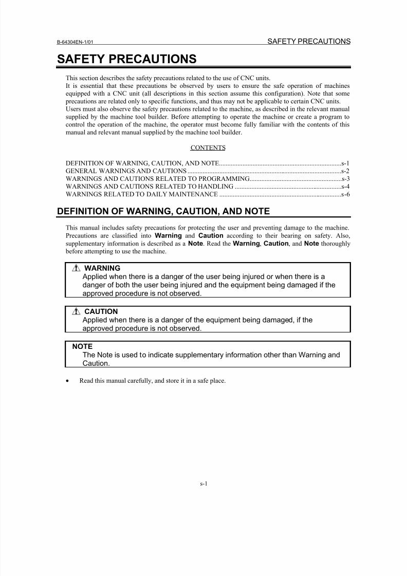
SAFETY PRECAUTIONS
This section describes the safety precautions related to the use of CNC units.
It is essential that these precautions be observed by users to ensure the safe operation of machines
equipped with a CNC unit (all descriptions in this section assume this configuration). Note that some
precautions are related only to specific functions, and thus may not be applicable to certain CNC units.
Users must also observe the safety precautions related to the machine, as described in the relevant manual
supplied by the machine tool builder. Before attempting to operate the machine or create a program to
control the operation of the machine, the operator must become fully familiar with the contents of this
manual and relevant manual supplied by the machine tool builder.
CONTENTS
DEFINITION OF WARNING, CAUTION, AND NOTE.........................................................................s-1
GENERAL WARNINGS AND CAUTIONS ............................................................................................s-2
WARNINGS AND CAUTIONS RELATED TO PROGRAMMING.......................................................s-3WARNINGS AND CAUTIONS RELATED TO HANDLING ................................................................s-4
WARNINGS RELATED TO DAILY MAINTENANCE .........................................................................s-6
DEFINITION OF WARNING, CAUTION, AND NOTE
This manual includes safety precautions for protecting the user and preventing damage to the machine.
Precautions are classified into Warning and Caution according to their bearing on safety. Also,
supplementary information is described as a Note. Read the Warning, Caution, and Note thoroughly
before attempting to use the machine.
WARNING Applied when there is a danger of the user being injured or when there is adanger of both the user being injured and the equipment being damaged if theapproved procedure is not observed.
CAUTION Applied when there is a danger of the equipment being damaged, if theapproved procedure is not observed.
NOTEThe Note is used to indicate supplementary information other than Warning and
Caution.
• Read this manual carefully, and store it in a safe place.
8/16/2019 Manual Operacion para FANUC
http://slidepdf.com/reader/full/manual-operacion-para-fanuc 4/435
SAFETY PRECAUTIONS B-64304EN-1/01
s-2
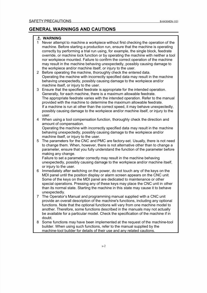
GENERAL WARNINGS AND CAUTIONS
WARNING1 Never attempt to machine a workpiece without first checking the operation of the
machine. Before starting a production run, ensure that the machine is operatingcorrectly by performing a trial run using, for example, the single block, feedrateoverride, or machine lock function or by operating the machine with neither a toolnor workpiece mounted. Failure to confirm the correct operation of the machinemay result in the machine behaving unexpectedly, possibly causing damage tothe workpiece and/or machine itself, or injury to the user.
2 Before operating the machine, thoroughly check the entered data.Operating the machine with incorrectly specified data may result in the machinebehaving unexpectedly, possibly causing damage to the workpiece and/ormachine itself, or injury to the user.
3 Ensure that the specified feedrate is appropriate for the intended operation.Generally, for each machine, there is a maximum allowable feedrate.The appropriate feedrate varies with the intended operation. Refer to the manualprovided with the machine to determine the maximum allowable feedrate.If a machine is run at other than the correct speed, it may behave unexpectedly,possibly causing damage to the workpiece and/or machine itself, or injury to theuser.
4 When using a tool compensation function, thoroughly check the direction andamount of compensation.Operating the machine with incorrectly specified data may result in the machinebehaving unexpectedly, possibly causing damage to the workpiece and/or
machine itself, or injury to the user.5 The parameters for the CNC and PMC are factory-set. Usually, there is not needto change them. When, however, there is not alternative other than to change aparameter, ensure that you fully understand the function of the parameter beforemaking any change.Failure to set a parameter correctly may result in the machine behavingunexpectedly, possibly causing damage to the workpiece and/or machine itself,or injury to the user.
6 Immediately after switching on the power, do not touch any of the keys on theMDI panel until the position display or alarm screen appears on the CNC unit.Some of the keys on the MDI panel are dedicated to maintenance or other
special operations. Pressing any of these keys may place the CNC unit in otherthan its normal state. Starting the machine in this state may cause it to behaveunexpectedly.
7 The Operator’s Manual and programming manual supplied with a CNC unitprovide an overall description of the machine's functions, including any optionalfunctions. Note that the optional functions will vary from one machine model toanother. Therefore, some functions described in the manuals may not actuallybe available for a particular model. Check the specification of the machine if indoubt.
8 Some functions may have been implemented at the request of the machine-toolbuilder. When using such functions, refer to the manual supplied by the
machine-tool builder for details of their use and any related cautions.
8/16/2019 Manual Operacion para FANUC
http://slidepdf.com/reader/full/manual-operacion-para-fanuc 5/435
B-64304EN-1/01 SAFETY PRECAUTIONS
s-3
CAUTIONThe liquid-crystal display is manufactured with very precise fabricationtechnology. Some pixels may not be turned on or may remain on. Thisphenomenon is a common attribute of LCDs and is not a defect.
NOTEPrograms, parameters, and macro variables are stored in nonvolatile memory inthe CNC unit. Usually, they are retained even if the power is turned off.Such data may be deleted inadvertently, however, or it may prove necessary todelete all data from nonvolatile memory as part of error recovery.To guard against the occurrence of the above, and assure quick restoration ofdeleted data, backup all vital data, and keep the backup copy in a safe place.
WARNINGS AND CAUTIONS RELATED TO PROGRAMMING
This section covers the major safety precautions related to programming. Before attempting to perform
programming, read the supplied Operator’s Manual carefully such that you are fully familiar with their
contents.
WARNING1 Coordinate system setting
If a coordinate system is established incorrectly, the machine may behaveunexpectedly as a result of the program issuing an otherwise valid movecommand. Such an unexpected operation may damage the tool, the machineitself, the workpiece, or cause injury to the user.
2 Positioning by nonlinear interpolation When performing positioning by nonlinear interpolation (positioning by nonlinearmovement between the start and end points), the tool path must be carefullyconfirmed before performing programming. Positioning involves rapid traverse. Ifthe tool collides with the workpiece, it may damage the tool, the machine itself,the workpiece, or cause injury to the user.
3 Function involving a rotation axis When programming polar coordinate interpolation, pay careful attention to thespeed of the rotation axis. Incorrect programming may result in the rotation axisspeed becoming excessively high, such that centrifugal force causes the chuckto lose its grip on the workpiece if the latter is not mounted securely. Such
mishap is likely to damage the tool, the machine itself, the workpiece, or causeinjury to the user.
4 Inch/metric conversion Switching between inch and metric inputs does not convert the measurementunits of data such as the workpiece origin offset, parameter, and currentposition. Before starting the machine, therefore, determine which measurementunits are being used. Attempting to perform an operation with invalid dataspecified may damage the tool, the machine itself, the workpiece, or cause injuryto the user.
8/16/2019 Manual Operacion para FANUC
http://slidepdf.com/reader/full/manual-operacion-para-fanuc 6/435
SAFETY PRECAUTIONS B-64304EN-1/01
s-4
WARNING5 Constant surface speed control
When an axis subject to constant surface speed control approaches the origin ofthe workpiece coordinate system, the spindle speed may become excessively
high. Therefore, it is necessary to specify a maximum allowable speed.Specifying the maximum allowable speed incorrectly may damage the tool, themachine itself, the workpiece, or cause injury to the user.
6 Stroke check After switching on the power, perform a manual reference position return asrequired. Stroke check is not possible before manual reference position return isperformed. Note that when stroke check is disabled, an alarm is not issued evenif a stroke limit is exceeded, possibly damaging the tool, the machine itself, theworkpiece, or causing injury to the user.
7 Interference check for each path An interference check for each path is performed based on the tool dataspecified during automatic operation. If the tool specification does not match thetool actually being used, the interference check cannot be made correctly,possibly damaging the tool or the machine itself, or causing injury to the user. After switching on the power, or after selecting a tool post manually, always startautomatic operation and specify the tool number of the tool to be used.
8 Absolute/incremental mode If a program created with absolute values is run in incremental mode, or viceversa, the machine may behave unexpectedly.
9 Plane selection If an incorrect plane is specified for circular interpolation, helical interpolation, or
a canned cycle, the machine may behave unexpectedly. Refer to thedescriptions of the respective functions for details.10 Torque limit skip
Before attempting a torque limit skip, apply the torque limit. If a torque limit skipis specified without the torque limit actually being applied, a move command willbe executed without performing a skip.
11 Compensation function If a command based on the machine coordinate system or a reference positionreturn command is issued in compensation function mode, compensation istemporarily canceled, resulting in the unexpected behavior of the machine.Before issuing any of the above commands, therefore, always cancel
compensation function mode.
WARNINGS AND CAUTIONS RELATED TO HANDLING
This section presents safety precautions related to the handling of machine tools. Before attempting to
operate your machine, read the supplied Operator’s Manual carefully, such that you are fully familiar
with their contents.
WARNING1 Manual operation
When operating the machine manually, determine the current position of the tool
and workpiece, and ensure that the movement axis, direction, and feedrate havebeen specified correctly. Incorrect operation of the machine may damage thetool, the machine itself, the workpiece, or cause injury to the operator.
8/16/2019 Manual Operacion para FANUC
http://slidepdf.com/reader/full/manual-operacion-para-fanuc 7/435
B-64304EN-1/01 SAFETY PRECAUTIONS
s-5
WARNING2 Manual reference position return
After switching on the power, perform manual reference position return asrequired.
If the machine is operated without first performing manual reference positionreturn, it may behave unexpectedly. Stroke check is not possible before manualreference position return is performed. An unexpected operation of the machine may damage the tool, the machineitself, the workpiece, or cause injury to the user.
3 Manual handle feed In manual handle feed, rotating the handle with a large scale factor, such as 100,applied causes the tool and table to move rapidly. Careless handling maydamage the tool and/or machine, or cause injury to the user.
4 Disabled override If override is disabled (according to the specification in a macro variable) duringthreading, rigid tapping, or other tapping, the speed cannot be predicted,possibly damaging the tool, the machine itself, the workpiece, or causing injuryto the operator.
5 Origin/preset operation Basically, never attempt an origin/preset operation when the machine isoperating under the control of a program. Otherwise, the machine may behaveunexpectedly, possibly damaging the tool, the machine itself, the tool, or causinginjury to the user.
6 Workpiece coordinate system shift Manual intervention, machine lock, or mirror imaging may shift the workpiece
coordinate system. Before attempting to operate the machine under the controlof a program, confirm the coordinate system carefully.If the machine is operated under the control of a program without makingallowances for any shift in the workpiece coordinate system, the machine maybehave unexpectedly, possibly damaging the tool, the machine itself, theworkpiece, or causing injury to the operator.
7 Software operator's panel and menu switches Using the software operator's panel and menu switches, in combination with theMDI panel, it is possible to specify operations not supported by the machineoperator's panel, such as mode change, override value change, and jog feedcommands.
Note, however, that if the MDI panel keys are operated inadvertently, themachine may behave unexpectedly, possibly damaging the tool, the machineitself, the workpiece, or causing injury to the user.
8 RESET keyPressing the RESET key stops the currently running program. As a result, theservo axes are stopped. However, the RESET key may fail to function forreasons such as an MDI panel problem. So, when the motors must be stopped,use the emergency stop button instead of the RESET key to ensure security.
9 Manual intervention If manual intervention is performed during programmed operation of themachine, the tool path may vary when the machine is restarted. Before restarting
the machine after manual intervention, therefore, confirm the settings of themanual absolute switches, parameters, and absolute/incremental commandmode.
8/16/2019 Manual Operacion para FANUC
http://slidepdf.com/reader/full/manual-operacion-para-fanuc 8/435
SAFETY PRECAUTIONS B-64304EN-1/01
s-6
WARNING10 Feed hold, override, and single block
The feed hold, feedrate override, and single block functions can be disabledusing custom macro system variable #3004. Be careful when operating the
machine in this case.11 Dry run
Usually, a dry run is used to confirm the operation of the machine. During a dryrun, the machine operates at dry run speed, which differs from thecorresponding programmed feedrate. Note that the dry run speed maysometimes be higher than the programmed feed rate.
12 Program editing If the machine is stopped, after which the machining program is edited(modification, insertion, or deletion), the machine may behave unexpectedly ifmachining is resumed under the control of that program. Basically, do notmodify, insert, or delete commands from a machining program while it is in use.
WARNINGS RELATED TO DAILY MAINTENANCE
WARNING1 Memory backup battery replacement
When replacing the memory backup batteries, keep the power to the machine(CNC) turned on, and apply an emergency stop to the machine. Because thiswork is performed with the power on and the cabinet open, only those personnelwho have received approved safety and maintenance training may perform thiswork.
When replacing the batteries, be careful not to touch the high-voltage circuits(marked and fitted with an insulating cover).Touching the uncovered high-voltage circuits presents an extremely dangerouselectric shock hazard.
NOTEThe CNC uses batteries to preserve the contents of its memory, because it mustretain data such as programs, offsets, and parameters even while externalpower is not applied.If the battery voltage drops, a low battery voltage alarm is displayed on themachine operator's panel or screen.
When a low battery voltage alarm is displayed, replace the batteries within aweek. Otherwise, the contents of the CNC's memory will be lost.Refer to the Section “Method of replacing battery” in the Operator’s Manual(Common to T/M series) for details of the battery replacement procedure.
8/16/2019 Manual Operacion para FANUC
http://slidepdf.com/reader/full/manual-operacion-para-fanuc 9/435
B-64304EN-1/01 SAFETY PRECAUTIONS
s-7
WARNING2 Absolute pulse coder battery replacement
When replacing the memory backup batteries, keep the power to the machine(CNC) turned on, and apply an emergency stop to the machine. Because this
work is performed with the power on and the cabinet open, only those personnelwho have received approved safety and maintenance training may perform thiswork.When replacing the batteries, be careful not to touch the high-voltage circuits(marked and fitted with an insulating cover).Touching the uncovered high-voltage circuits presents an extremely dangerouselectric shock hazard.
NOTEThe absolute pulse coder uses batteries to preserve its absolute position.If the battery voltage drops, a low battery voltage alarm is displayed on themachine operator's panel or screen.When a low battery voltage alarm is displayed, replace the batteries within aweek. Otherwise, the absolute position data held by the pulse coder will be lost.Refer to the Section “Method of replacing battery” in the Operator’s Manual(Common to T/M series) for details of the battery replacement procedure.
WARNING3 Fuse replacement
Before replacing a blown fuse, however, it is necessary to locate and remove thecause of the blown fuse.
For this reason, only those personnel who have received approved safety andmaintenance training may perform this work.When replacing a fuse with the cabinet open, be careful not to touch thehigh-voltage circuits (marked and fitted with an insulating cover).Touching an uncovered high-voltage circuit presents an extremely dangerouselectric shock hazard.

8/16/2019 Manual Operacion para FANUC
http://slidepdf.com/reader/full/manual-operacion-para-fanuc 10/435
8/16/2019 Manual Operacion para FANUC
http://slidepdf.com/reader/full/manual-operacion-para-fanuc 11/435
B-64304EN-1/01 TABLE OF CONTENTS
c-1
TABLE OF CONTENTS
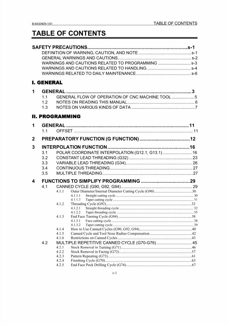
SAFETY PRECAUTIONS............................................................................s-1DEFINITION OF WARNING, CAUTION, AND NOTE ............................................. s-1
GENERAL WARNINGS AND CAUTIONS............................................................... s-2
WARNINGS AND CAUTIONS RELATED TO PROGRAMMING ............................ s-3
WARNINGS AND CAUTIONS RELATED TO HANDLING...................................... s-4
WARNINGS RELATED TO DAILY MAINTENANCE............................................... s-6
I GENERAL
1 GENERAL ...............................................................................................31.1 GENERAL FLOW OF OPERATION OF CNC MACHINE TOOL ................... 5
1.2 NOTES ON READING THIS MANUAL.......................................................... 61.3 NOTES ON VARIOUS KINDS OF DATA ......................................................7
II PROGRAMMING
1 GENERAL .............................................................................................111.1 OFFSET ......................................................................................................11
2 PREPARATORY FUNCTION (G FUNCTION) ......................................12
3 INTERPOLATION FUNCTION..............................................................16
3.1 POLAR COORDINATE INTERPOLATION (G12.1, G13.1) ......................... 163.2 CONSTANT LEAD THREADING (G32) ......................................................23
3.3 VARIABLE LEAD THREADING (G34)......................................................... 26
3.4 CONTINUOUS THREADING....................................................................... 27
3.5 MULTIPLE THREADING.............................................................................27
4 FUNCTIONS TO SIMPLIFY PROGRAMMING .....................................294.1 CANNED CYCLE (G90, G92, G94) ............................................................. 29
4.1.1 Outer Diameter/Internal Diameter Cutting Cycle (G90) ........................................304.1.1.1 Straight cutting cycle ................................................................. ........................ 30
4.1.1.2 Taper cutting cycle ........................................................................... ................. 31
4.1.2 Threading Cycle (G92)...........................................................................................324.1.2.1 Straight threading cycle ............................................................ ......................... 32
4.1.2.2 Taper threading cycle ................................................................. ....................... 35
4.1.3 End Face Turning Cycle (G94) ..............................................................................384.1.3.1 Face cutting cycle ................................................................. ............................. 38
4.1.3.2 Taper cutting cycle .................................................................. .......................... 39
4.1.4 How to Use Canned Cycles (G90, G92, G94)........................................................40
4.1.5 Canned Cycle and Tool Nose Radius Compensation.............................................42
4.1.6 Restrictions on Canned Cycles...............................................................................43
4.2 MULTIPLE REPETITIVE CANNED CYCLE (G70-G76) .............................. 454.2.1 Stock Removal in Turning (G71)...........................................................................46
4.2.2 Stock Removal in Facing (G72) .............................................................................57
4.2.3 Pattern Repeating (G73).........................................................................................614.2.4 Finishing Cycle (G70)............................................................................................63
4.2.5 End Face Peck Drilling Cycle (G74)......................................................................67
8/16/2019 Manual Operacion para FANUC
http://slidepdf.com/reader/full/manual-operacion-para-fanuc 12/435
TABLE OF CONTENTS B-64304EN-1/01
c-2
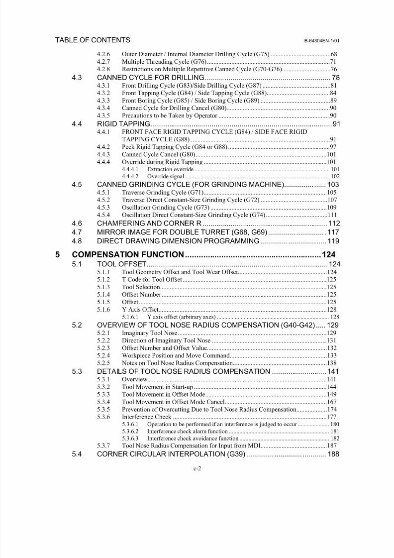
4.2.6 Outer Diameter / Internal Diameter Drilling Cycle (G75) .....................................68
4.2.7 Multiple Threading Cycle (G76)............................................................................71
4.2.8 Restrictions on Multiple Repetitive Canned Cycle (G70-G76)..............................76
4.3 CANNED CYCLE FOR DRILLING............................................................... 78
4.3.1 Front Drilling Cycle (G83)/Side Drilling Cycle (G87) ..........................................814.3.2 Front Tapping Cycle (G84) / Side Tapping Cycle (G88).......................................84
4.3.3 Front Boring Cycle (G85) / Side Boring Cycle (G89) ...........................................89
4.3.4 Canned Cycle for Drilling Cancel (G80)................................................................90
4.3.5 Precautions to be Taken by Operator .....................................................................90
4.4 RIGID TAPPING..........................................................................................914.4.1 FRONT FACE RIGID TAPPING CYCLE (G84) / SIDE FACE RIGID
TAPPING CYCLE (G88) ......................................................................................91
4.4.2 Peck Rigid Tapping Cycle (G84 or G88) ...............................................................97
4.4.3 Canned Cycle Cancel (G80).................................................................................101
4.4.4 Override during Rigid Tapping ............................................................................1014.4.4.1 Extraction override ........................................................... ............................... 101
4.4.4.2 Override signal ............................................................ .................................... 102
4.5 CANNED GRINDING CYCLE (FOR GRINDING MACHINE)..................... 1034.5.1 Traverse Grinding Cycle (G71)............................................................................105
4.5.2 Traverse Direct Constant-Size Grinding Cycle (G72) .........................................107
4.5.3 Oscillation Grinding Cycle (G73) ........................................................................109
4.5.4 Oscillation Direct Constant-Size Grinding Cycle (G74)......................................111
4.6 CHAMFERING AND CORNER R..............................................................112
4.7 MIRROR IMAGE FOR DOUBLE TURRET (G68, G69) ............................. 117
4.8 DIRECT DRAWING DIMENSION PROGRAMMING................................. 119
5 COMPENSATION FUNCTION............................................................124
5.1 TOOL OFFSET..........................................................................................1245.1.1 Tool Geometry Offset and Tool Wear Offset.......................................................124
5.1.2 T Code for Tool Offset .........................................................................................125
5.1.3 Tool Selection.......................................................................................................125
5.1.4 Offset Number......................................................................................................125
5.1.5 Offset ....................................................................................................................125
5.1.6 Y Axis Offset........................................................................................................1285.1.6.1 Y axis offset (arbitrary axes) ........................................................................... 128
5.2 OVERVIEW OF TOOL NOSE RADIUS COMPENSATION (G40-G42) ..... 1295.2.1 Imaginary Tool Nose............................................................................................129
5.2.2 Direction of Imaginary Tool Nose .......................................................................131
5.2.3 Offset Number and Offset Value..........................................................................1325.2.4 Workpiece Position and Move Command............................................................133
5.2.5 Notes on Tool Nose Radius Compensation..........................................................138
5.3 DETAILS OF TOOL NOSE RADIUS COMPENSATION ...........................1415.3.1 Overview ..............................................................................................................141
5.3.2 Tool Movement in Start-up ..................................................................................144
5.3.3 Tool Movement in Offset Mode...........................................................................149
5.3.4 Tool Movement in Offset Mode Cancel...............................................................167
5.3.5 Prevention of Overcutting Due to Tool Nose Radius Compensation...................174
5.3.6 Interference Check ...............................................................................................1775.3.6.1 Operation to be performed if an interference is judged to occur ..................... 180
5.3.6.2 Interference check alarm function ................................................................... 181
5.3.6.3 Interference check avoidance function ............................................................ 1825.3.7 Tool Nose Radius Compensation for Input from MDI.........................................187
5.4 CORNER CIRCULAR INTERPOLATION (G39) ........................................ 188
8/16/2019 Manual Operacion para FANUC
http://slidepdf.com/reader/full/manual-operacion-para-fanuc 13/435
B-64304EN-1/01 TABLE OF CONTENTS
c-3
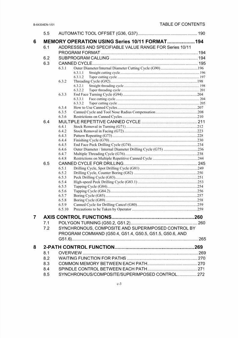
5.5 AUTOMATIC TOOL OFFSET (G36, G37)................................................. 190
6 MEMORY OPERATION USING Series 10/11 FORMAT....................1946.1 ADDRESSES AND SPECIFIABLE VALUE RANGE FOR Series 10/11
PROGRAM FORMAT................................................................................ 1946.2 SUBPROGRAM CALLING ........................................................................194
6.3 CANNED CYCLE....................................................................................... 1956.3.1 Outer Diameter/Internal Diameter Cutting Cycle (G90) ......................................196
6.3.1.1 Straight cutting cycle ..................................................................... .................. 196
6.3.1.2 Taper cutting cycle .................................................................. ........................ 197
6.3.2 Threading Cycle (G92).........................................................................................1986.3.2.1 Straight threading cycle ................................................................ ................... 198
6.3.2.2 Taper threading cycle .............................................................. ........................ 201
6.3.3 End Face Turning Cycle (G94) ............................................................................2046.3.3.1 Face cutting cycle ................................................................. ........................... 204
6.3.3.2 Taper cutting cycle ..................................................................... ..................... 205
6.3.4 How to Use Canned Cycles..................................................................................2076.3.5 Canned Cycle and Tool Nose Radius Compensation...........................................208
6.3.6 Restrictions on Canned Cycles.............................................................................210
6.4 MULTIPLE REPETITIVE CANNED CYCLE .............................................. 2116.4.1 Stock Removal in Turning (G71) .........................................................................212
6.4.2 Stock Removal in Facing (G72) ...........................................................................223
6.4.3 Pattern Repeating (G73).......................................................................................228
6.4.4 Finishing Cycle (G70)..........................................................................................230
6.4.5 End Face Peck Drilling Cycle (G74)....................................................................234
6.4.6 Outer Diameter / Internal Diameter Drilling Cycle (G75) ...................................236
6.4.7 Multiple Threading Cycle (G76)..........................................................................238
6.4.8 Restrictions on Multiple Repetitive Canned Cycle ..............................................2446.5 CANNED CYCLE FOR DRILLING............................................................. 245
6.5.1 Drilling Cycle, Spot Drilling Cycle (G81) ...........................................................249
6.5.2 Drilling Cycle, Counter Boring (G82) .................................................................250
6.5.3 Peck Drilling Cycle (G83)....................................................................................251
6.5.4 High-speed Peck Drilling Cycle (G83.1) .............................................................253
6.5.5 Tapping Cycle (G84)............................................................................................254
6.5.6 Tapping Cycle (G84.2).........................................................................................256
6.5.7 Boring Cycle (G85)..............................................................................................257
6.5.8 Boring Cycle (G89)..............................................................................................258
6.5.9 Canned Cycle for Drilling Cancel (G80)..............................................................259
6.5.10 Precautions to be Taken by Operator ...................................................................259
7 AXIS CONTROL FUNCTIONS............................................................2607.1 POLYGON TURNING (G50.2, G51.2)....................................................... 260
7.2 SYNCHRONOUS, COMPOSITE AND SUPERIMPOSED CONTROL BY
PROGRAM COMMAND (G50.4, G51.4, G50.5, G51.5, G50.6, AND
G51.6)........................................................................................................265
8 2-PATH CONTROL FUNCTION..........................................................2698.1 OVERVIEW ...............................................................................................269
8.2 WAITING FUNCTION FOR PATHS .......................................................... 270
8.3 COMMON MEMORY BETWEEN EACH PATH......................................... 2708.4 SPINDLE CONTROL BETWEEN EACH PATH......................................... 271
8.5 SYNCHRONOUS/COMPOSITE/SUPERIMPOSED CONTROL................ 272
8/16/2019 Manual Operacion para FANUC
http://slidepdf.com/reader/full/manual-operacion-para-fanuc 14/435
TABLE OF CONTENTS B-64304EN-1/01
c-4
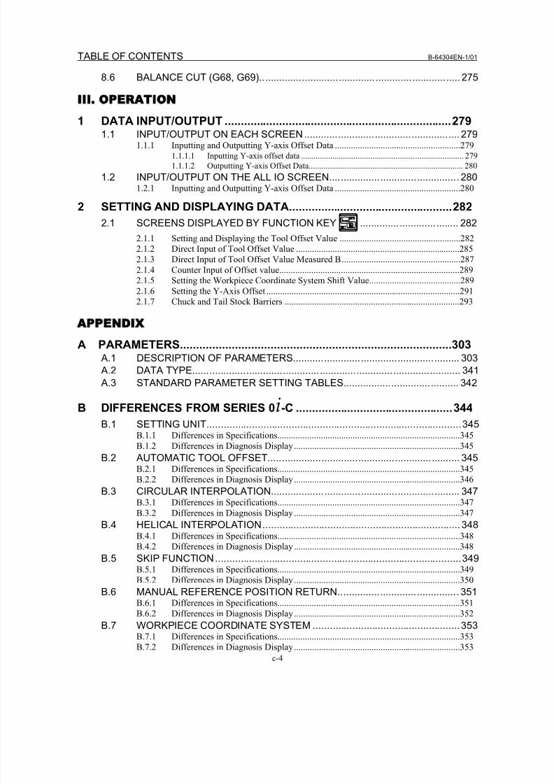
8.6 BALANCE CUT (G68, G69)....................................................................... 275
III OPERATION
1 DATA INPUT/OUTPUT .......................................................................2791.1 INPUT/OUTPUT ON EACH SCREEN....................................................... 279
1.1.1 Inputting and Outputting Y-axis Offset Data .......................................................2791.1.1.1 Inputting Y-axis offset data ...................................................... ....................... 279
1.1.1.2 Outputting Y-axis Offset Data.................. ....................................................... 280
1.2 INPUT/OUTPUT ON THE ALL IO SCREEN.............................................. 2801.2.1 Inputting and Outputting Y-axis Offset Data .......................................................280
2 SETTING AND DISPLAYING DATA...................................................282
2.1 SCREENS DISPLAYED BY FUNCTION KEY ................................... 282
2.1.1 Setting and Displaying the Tool Offset Value .....................................................282
2.1.2 Direct Input of Tool Offset Value ........................................................................2852.1.3 Direct Input of Tool Offset Value Measured B....................................................287
2.1.4 Counter Input of Offset value...............................................................................289
2.1.5 Setting the Workpiece Coordinate System Shift Value........................................289
2.1.6 Setting the Y-Axis Offset .....................................................................................291
2.1.7 Chuck and Tail Stock Barriers .............................................................................293
APPENDIX
A PARAMETERS....................................................................................303 A.1 DESCRIPTION OF PARAMETERS........................................................... 303
A.2 DATA TYPE............................................................................................... 341 A.3 STANDARD PARAMETER SETTING TABLES......................................... 342
B DIFFERENCES FROM SERIES 0i-C .................................................344
B.1 SETTING UNIT..........................................................................................345B.1.1 Differences in Specifications................................................................................345
B.1.2 Differences in Diagnosis Display .........................................................................345
B.2 AUTOMATIC TOOL OFFSET.................................................................... 345B.2.1 Differences in Specifications................................................................................345
B.2.2 Differences in Diagnosis Display .........................................................................346
B.3 CIRCULAR INTERPOLATION................................................................... 347B.3.1 Differences in Specifications................................................................................347
B.3.2 Differences in Diagnosis Display .........................................................................347
B.4 HELICAL INTERPOLATION...................................................................... 348B.4.1 Differences in Specifications................................................................................348
B.4.2 Differences in Diagnosis Display .........................................................................348
B.5 SKIP FUNCTION.......................................................................................349B.5.1 Differences in Specifications................................................................................349
B.5.2 Differences in Diagnosis Display .........................................................................350
B.6 MANUAL REFERENCE POSITION RETURN........................................... 351B.6.1 Differences in Specifications................................................................................351
B.6.2 Differences in Diagnosis Display .........................................................................352B.7 WORKPIECE COORDINATE SYSTEM ....................................................353
B.7.1 Differences in Specifications................................................................................353
B.7.2 Differences in Diagnosis Display .........................................................................353
8/16/2019 Manual Operacion para FANUC
http://slidepdf.com/reader/full/manual-operacion-para-fanuc 15/435
B-64304EN-1/01 TABLE OF CONTENTS
c-5
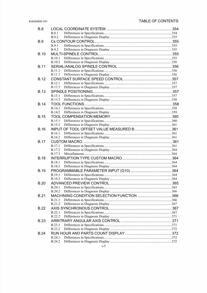
B.8 LOCAL COORDINATE SYSTEM ..............................................................354B.8.1 Differences in Specifications................................................................................354
B.8.2 Differences in Diagnosis Display .........................................................................355
B.9 Cs CONTOUR CONTROL......................................................................... 355
B.9.1 Differences in Specifications................................................................................355B.9.2 Differences in Diagnosis Display .........................................................................355
B.10 MULTI-SPINDLE CONTROL..................................................................... 355B.10.1 Differences in Specifications................................................................................355
B.10.2 Differences in Diagnosis Display.........................................................................356
B.11 SERIAL/ANALOG SPINDLE CONTROL ...................................................356B.11.1 Differences in Specifications................................................................................356
B.11.2 Differences in Diagnosis Display.........................................................................356
B.12 CONSTANT SURFACE SPEED CONTROL ............................................. 357B.12.1 Differences in Specifications................................................................................357
B.12.2 Differences in Diagnosis Display.........................................................................357
B.13 SPINDLE POSITIONING........................................................................... 357B.13.1 Differences in Specifications................................................................................357
B.13.2 Differences in Diagnosis Display.........................................................................358
B.14 TOOL FUNCTIONS...................................................................................358B.14.1 Differences in Specifications................................................................................358
B.14.2 Differences in Diagnosis Display.........................................................................359
B.15 TOOL COMPENSATION MEMORY.......................................................... 360B.15.1 Differences in Specifications................................................................................360
B.15.2 Differences in Diagnosis Display.........................................................................361
B.16 INPUT OF TOOL OFFSET VALUE MEASURED B................................... 361B.16.1 Differences in Specifications................................................................................361
B.16.2 Differences in Diagnosis Display.........................................................................361B.17 CUSTOM MACRO..................................................................................... 361
B.17.1 Differences in Specifications................................................................................361
B.17.2 Differences in Diagnosis Display.........................................................................364
B.17.3 Miscellaneous.......................................................................................................364
B.18 INTERRUPTION TYPE CUSTOM MACRO............................................... 364B.18.1 Differences in Specifications................................................................................364
B.18.2 Differences in Diagnosis Display.........................................................................364
B.19 PROGRAMMABLE PARAMETER INPUT (G10) ....................................... 364B.19.1 Differences in Specifications................................................................................364
B.19.2 Differences in Diagnosis Display.........................................................................364
B.20 ADVANCED PREVIEW CONTROL........................................................... 365B.20.1 Differences in Specifications................................................................................365
B.20.2 Differences in Diagnosis Display.........................................................................366
B.21 MACHINING CONDITION SELECTION FUNCTION ................................366B.21.1 Differences in Specifications................................................................................366
B.21.2 Differences in Diagnosis Display.........................................................................367
B.22 AXIS SYNCHRONOUS CONTROL........................................................... 367B.22.1 Differences in Specifications................................................................................367
B.22.2 Differences in Diagnosis Display.........................................................................371
B.23 ARBITRARY ANGULAR AXIS CONTROL ................................................ 371B.23.1 Differences in Specifications................................................................................371
B.23.2 Differences in Diagnosis Display.........................................................................372B.24 RUN HOUR AND PARTS COUNT DISPLAY ............................................ 372
B.24.1 Differences in Specifications................................................................................372
B.24.2 Differences in Diagnosis Display.........................................................................372
8/16/2019 Manual Operacion para FANUC
http://slidepdf.com/reader/full/manual-operacion-para-fanuc 16/435
TABLE OF CONTENTS B-64304EN-1/01
c-6
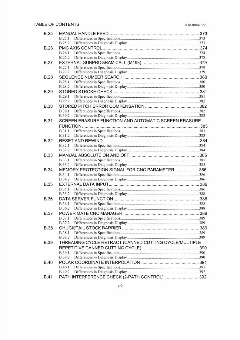
B.25 MANUAL HANDLE FEED.......................................................................... 373B.25.1 Differences in Specifications................................................................................373
B.25.2 Differences in Diagnosis Display.........................................................................373
B.26 PMC AXIS CONTROL............................................................................... 374
B.26.1 Differences in Specifications................................................................................374B.26.2 Differences in Diagnosis Display.........................................................................378
B.27 EXTERNAL SUBPROGRAM CALL (M198)............................................... 379B.27.1 Differences in Specifications................................................................................379
B.27.2 Differences in Diagnosis Display.........................................................................379
B.28 SEQUENCE NUMBER SEARCH ..............................................................380B.28.1 Differences in Specifications................................................................................380
B.28.2 Differences in Diagnosis Display.........................................................................380
B.29 STORED STROKE CHECK....................................................................... 381B.29.1 Differences in Specifications................................................................................381
B.29.2 Differences in Diagnosis Display.........................................................................382
B.30 STORED PITCH ERROR COMPENSATION ............................................ 382B.30.1 Differences in Specifications................................................................................382
B.30.2 Differences in Diagnosis Display.........................................................................383
B.31 SCREEN ERASURE FUNCTION AND AUTOMATIC SCREEN ERASURE
FUNCTION ................................................................................................383B.31.1 Differences in Specifications................................................................................383
B.31.2 Differences in Diagnosis Display.........................................................................383
B.32 RESET AND REWIND............................................................................... 384B.32.1 Differences in Specifications................................................................................384
B.32.2 Differences in Diagnosis Display.........................................................................384
B.33 MANUAL ABSOLUTE ON AND OFF......................................................... 385
B.33.1 Differences in Specifications................................................................................385B.33.2 Differences in Diagnosis Display.........................................................................385
B.34 MEMORY PROTECTION SIGNAL FOR CNC PARAMETER.................... 386B.34.1 Differences in Specifications................................................................................386
B.34.2 Differences in Diagnosis Display.........................................................................386
B.35 EXTERNAL DATA INPUT.......................................................................... 386B.35.1 Differences in Specifications................................................................................386
B.35.2 Differences in Diagnosis Display.........................................................................388
B.36 DATA SERVER FUNCTION...................................................................... 388B.36.1 Differences in Specifications................................................................................388
B.36.2 Differences in Diagnosis Display.........................................................................388
B.37 POWER MATE CNC MANAGER ..............................................................389B.37.1 Differences in Specifications................................................................................389
B.37.2 Differences in Diagnosis Display.........................................................................389
B.38 CHUCK/TAIL STOCK BARRIER ...............................................................389B.38.1 Differences in Specifications................................................................................389
B.38.2 Differences in Diagnosis Display.........................................................................389
B.39 THREADING CYCLE RETRACT (CANNED CUTTING CYCLE/MULTIPLE
REPETITIVE CANNED CUTTING CYCLE)............................................... 390B.39.1 Differences in Specifications................................................................................390
B.39.2 Differences in Diagnosis Display.........................................................................390
B.40 POLAR COORDINATE INTERPOLATION................................................ 391
B.40.1 Differences in Specifications................................................................................391B.40.2 Differences in Diagnosis Display.........................................................................392
B.41 PATH INTERFERENCE CHECK (2-PATH CONTROL) ............................ 392
8/16/2019 Manual Operacion para FANUC
http://slidepdf.com/reader/full/manual-operacion-para-fanuc 17/435
B-64304EN-1/01 TABLE OF CONTENTS
c-7
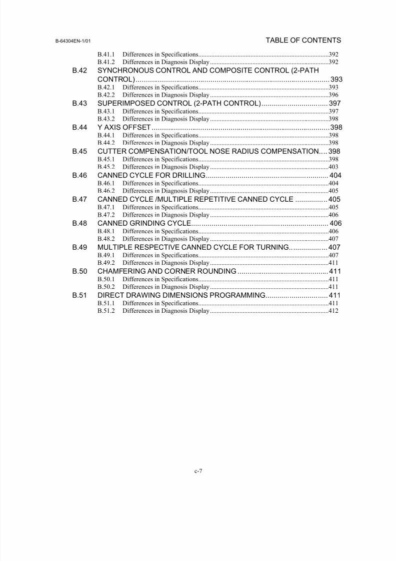
B.41.1 Differences in Specifications................................................................................392
B.41.2 Differences in Diagnosis Display.........................................................................392
B.42 SYNCHRONOUS CONTROL AND COMPOSITE CONTROL (2-PATH
CONTROL)................................................................................................393
B.42.1 Differences in Specifications................................................................................393B.42.2 Differences in Diagnosis Display.........................................................................396
B.43 SUPERIMPOSED CONTROL (2-PATH CONTROL)................................. 397B.43.1 Differences in Specifications................................................................................397
B.43.2 Differences in Diagnosis Display.........................................................................398
B.44 Y AXIS OFFSET........................................................................................398B.44.1 Differences in Specifications................................................................................398
B.44.2 Differences in Diagnosis Display.........................................................................398
B.45 CUTTER COMPENSATION/TOOL NOSE RADIUS COMPENSATION.... 398B.45.1 Differences in Specifications................................................................................398
B.45.2 Differences in Diagnosis Display.........................................................................403
B.46 CANNED CYCLE FOR DRILLING............................................................. 404B.46.1 Differences in Specifications................................................................................404
B.46.2 Differences in Diagnosis Display.........................................................................405
B.47 CANNED CYCLE /MULTIPLE REPETITIVE CANNED CYCLE ................ 405B.47.1 Differences in Specifications................................................................................405
B.47.2 Differences in Diagnosis Display.........................................................................406
B.48 CANNED GRINDING CYCLE.................................................................... 406B.48.1 Differences in Specifications................................................................................406
B.48.2 Differences in Diagnosis Display.........................................................................407
B.49 MULTIPLE RESPECTIVE CANNED CYCLE FOR TURNING................... 407B.49.1 Differences in Specifications................................................................................407
B.49.2 Differences in Diagnosis Display.........................................................................411B.50 CHAMFERING AND CORNER ROUNDING ............................................. 411
B.50.1 Differences in Specifications................................................................................411
B.50.2 Differences in Diagnosis Display.........................................................................411
B.51 DIRECT DRAWING DIMENSIONS PROGRAMMING............................... 411B.51.1 Differences in Specifications................................................................................411
B.51.2 Differences in Diagnosis Display.........................................................................412

8/16/2019 Manual Operacion para FANUC
http://slidepdf.com/reader/full/manual-operacion-para-fanuc 18/435

8/16/2019 Manual Operacion para FANUC
http://slidepdf.com/reader/full/manual-operacion-para-fanuc 19/435
I. GENERAL

8/16/2019 Manual Operacion para FANUC
http://slidepdf.com/reader/full/manual-operacion-para-fanuc 20/435
8/16/2019 Manual Operacion para FANUC
http://slidepdf.com/reader/full/manual-operacion-para-fanuc 21/435
B-64304EN-1/01 GENERAL 1.GENERAL
- 3 -
1 GENERAL
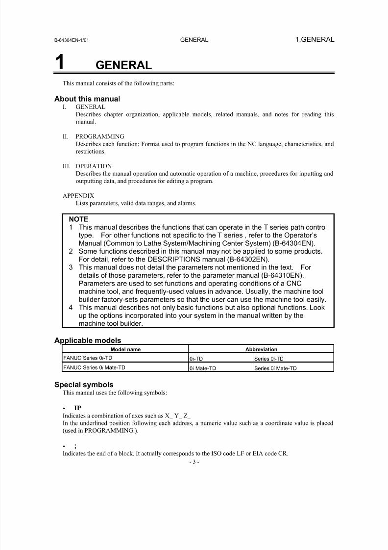
This manual consists of the following parts:
About this manualI. GENERAL
Describes chapter organization, applicable models, related manuals, and notes for reading this
manual.
II. PROGRAMMING
Describes each function: Format used to program functions in the NC language, characteristics, and
restrictions.
III. OPERATION
Describes the manual operation and automatic operation of a machine, procedures for inputting andoutputting data, and procedures for editing a program.
APPENDIX
Lists parameters, valid data ranges, and alarms.
NOTE1 This manual describes the functions that can operate in the T series path control
type. For other functions not specific to the T series , refer to the Operator’sManual (Common to Lathe System/Machining Center System) (B-64304EN).
2 Some functions described in this manual may not be applied to some products.
For detail, refer to the DESCRIPTIONS manual (B-64302EN).3 This manual does not detail the parameters not mentioned in the text. For
details of those parameters, refer to the parameter manual (B-64310EN).Parameters are used to set functions and operating conditions of a CNCmachine tool, and frequently-used values in advance. Usually, the machine toolbuilder factory-sets parameters so that the user can use the machine tool easily.
4 This manual describes not only basic functions but also optional functions. Lookup the options incorporated into your system in the manual written by themachine tool builder.
Applicable modelsModel name Abbreviation
FANUC Series 0i-TD 0i-TD Series 0i-TD
FANUC Series 0i Mate-TD 0i Mate-TD Series 0i Mate-TD
Special symbolsThis manual uses the following symbols:
- IP Indicates a combination of axes such as X_ Y_ Z_
In the underlined position following each address, a numeric value such as a coordinate value is placed
(used in PROGRAMMING.).
- ;Indicates the end of a block. It actually corresponds to the ISO code LF or EIA code CR.
8/16/2019 Manual Operacion para FANUC
http://slidepdf.com/reader/full/manual-operacion-para-fanuc 22/435
1.GENERAL GENERAL B-64304EN-1/01
- 4 -
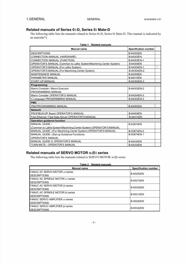
Related manuals of Series 0i-D, Series 0i Mate-DThe following table lists the manuals related to Series 0i-D, Series 0i Mate-D. This manual is indicated by
an asterisk(*).
Table 1 Related manuals
Manual name Specification number
DESCRIPTIONS B-64302EN
CONNECTION MANUAL (HARDWARE) B-64303EN
CONNECTION MANUAL (FUNCTION) B-64303EN-1
OPERATOR’S MANUAL (Common to Lathe System/Machining Center System) B-64304EN
OPERATOR’S MANUAL (For Lathe System) B-64304EN-1 *
OPERATOR’S MANUAL (For Machining Center System) B-64304EN-2
MAINTENANCE MANUAL B-64305EN
PARAMETER MANUAL B-64310EN
START-UP MANUAL B-64304EN-3
Programming
Macro Compiler / Macro Executor
PROGRAMMING MANUAL
B-64303EN-2
Macro Compiler OPERATOR’S MANUAL B-64304EN-5
C Language PROGRAMMING MANUAL B-64303EN-3
PMC
PMCPROGRAMMING MANUAL B-64393EN
Network
PROFIBUS-DP Board OPERATOR’S MANUAL B-64404EN
Fast Ethernet / Fast Data Server OPERATOR’S MANUAL B-64414EN
Operation guidance function
MANUAL GUIDE i (Common to Lathe System/Machining Center System) OPERATOR’S MANUAL
B-63874EN
MANUAL GUIDE i (For Machining Center System) OPERATOR’S MANUAL B-63874EN-2
MANUAL GUIDE i (Set-up Guidance Functions)
OPERATOR’S MANUAL
B-63874EN-1
MANUAL GUIDE 0i OPERATOR’S MANUAL B-64434EN
TURN MATE i OPERATOR’S MANUAL B-64254EN
Related manuals of SERVO MOTOR i / i seriesThe following table lists the manuals related to SERVO MOTOR αi/βi series
Table 2 Related manuals
Manual name Specification number
FANUC AC SERVO MOTOR αi series
DESCRIPTIONSB-65262EN
FANUC AC SPINDLE MOTOR αi series
DESCRIPTIONSB-65272EN
FANUC AC SERVO MOTOR βi series
DESCRIPTIONSB-65302EN
FANUC AC SPINDLE MOTOR βi series
DESCRIPTIONSB-65312EN
FANUC SERVO AMPLIFIER αi series
DESCRIPTIONSB-65282EN
FANUC SERVO AMPLIFIER βi series
DESCRIPTIONS B-65322EN
8/16/2019 Manual Operacion para FANUC
http://slidepdf.com/reader/full/manual-operacion-para-fanuc 23/435
B-64304EN-1/01 GENERAL 1.GENERAL
- 5 -
Manual name Specification number
FANUC SERVO MOTOR αis series
FANUC SERVO MOTOR αi series
FANUC AC SPINDLE MOTOR αi series
FANUC SERVO AMPLIFIER αi series
MAINTENANCE MANUAL
B-65285EN
FANUC SERVO MOTOR βis series
FANUC AC SPINDLE MOTOR βi series
FANUC SERVO AMPLIFIER βi series
MAINTENANCE MANUAL
B-65325EN
FANUC AC SERVO MOTOR αi/βi series,
FANUC LINEAR MOTOR LiS series
FANUC SYNCHRONOUS BUILT-IN SERVO MOTOR DiS series PARAMETER
MANUAL
B-65270EN
FANUC AC SPINDLE MOTOR αi/βi series,
BUILT-IN SPINDLE MOTOR Bi series
PARAMETER MANUAL
B-65280EN
This manual mainly assumes that the FANUC SERVO MOTOR αi series of servo motor is used. For
servo motor and spindle information, refer to the manuals for the servo motor and spindle that are actually
connected.
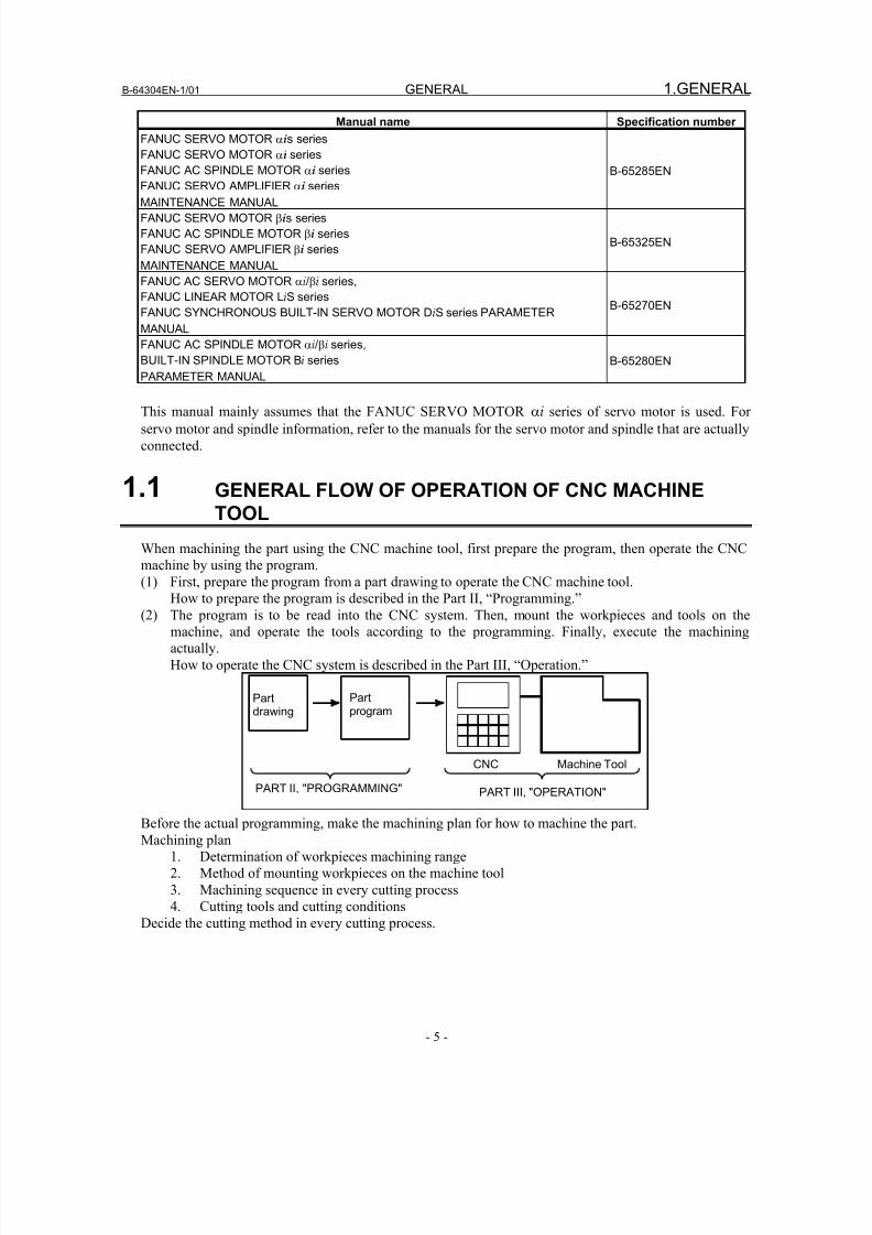
1.1 GENERAL FLOW OF OPERATION OF CNC MACHINE
TOOL
When machining the part using the CNC machine tool, first prepare the program, then operate the CNC
machine by using the program.
(1) First, prepare the program from a part drawing to operate the CNC machine tool.How to prepare the program is described in the Part II, “Programming.”
(2) The program is to be read into the CNC system. Then, mount the workpieces and tools on the
machine, and operate the tools according to the programming. Finally, execute the machining
actually.
How to operate the CNC system is described in the Part III, “Operation.”
Partprogram
Partdrawing
CNC Machine Tool
PART II, "PROGRAMMING" PART III, "OPERATION"
Before the actual programming, make the machining plan for how to machine the part.
Machining plan
1. Determination of workpieces machining range
2. Method of mounting workpieces on the machine tool
3. Machining sequence in every cutting process
4. Cutting tools and cutting conditions
Decide the cutting method in every cutting process.
8/16/2019 Manual Operacion para FANUC
http://slidepdf.com/reader/full/manual-operacion-para-fanuc 24/435
1.GENERAL GENERAL B-64304EN-1/01
- 6 -
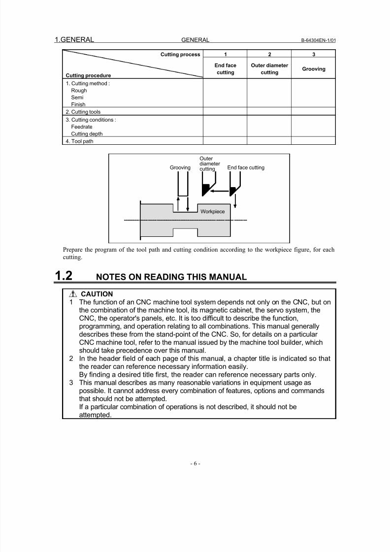
1 2 3Cutting process
Cutting procedure
End face
cutting
Outer diameter
cuttingGrooving
1. Cutting method :
Rough
Semi
Finish
2. Cutting tools
3. Cutting conditions :
Feedrate
Cutting depth
4. Tool path
Grooving
Outerdiametercutting End face cutting
Workpiece
Prepare the program of the tool path and cutting condition according to the workpiece figure, for each
cutting.
1.2 NOTES ON READING THIS MANUAL
CAUTION1 The function of an CNC machine tool system depends not only on the CNC, but on
the combination of the machine tool, its magnetic cabinet, the servo system, theCNC, the operator's panels, etc. It is too difficult to describe the function,programming, and operation relating to all combinations. This manual generallydescribes these from the stand-point of the CNC. So, for details on a particularCNC machine tool, refer to the manual issued by the machine tool builder, whichshould take precedence over this manual.
2 In the header field of each page of this manual, a chapter title is indicated so thatthe reader can reference necessary information easily.By finding a desired title first, the reader can reference necessary parts only.
3 This manual describes as many reasonable variations in equipment usage aspossible. It cannot address every combination of features, options and commandsthat should not be attempted.If a particular combination of operations is not described, it should not beattempted.

8/16/2019 Manual Operacion para FANUC
http://slidepdf.com/reader/full/manual-operacion-para-fanuc 25/435
B-64304EN-1/01 GENERAL 1.GENERAL
- 7 -
1.3 NOTES ON VARIOUS KINDS OF DATA
CAUTION
Machining programs, parameters, offset data, etc. are stored in the CNC unitinternal non-volatile memory. In general, these contents are not lost by theswitching ON/OFF of the power. However, it is possible that a state can occurwhere precious data stored in the non-volatile memory has to be deleted,because of deletions from a maloperation, or by a failure restoration. In order torestore rapidly when this kind of mishap occurs, it is recommended that youcreate a copy of the various kinds of data beforehand.

8/16/2019 Manual Operacion para FANUC
http://slidepdf.com/reader/full/manual-operacion-para-fanuc 26/435

8/16/2019 Manual Operacion para FANUC
http://slidepdf.com/reader/full/manual-operacion-para-fanuc 27/435
II. PROGRAMMING

8/16/2019 Manual Operacion para FANUC
http://slidepdf.com/reader/full/manual-operacion-para-fanuc 28/435
8/16/2019 Manual Operacion para FANUC
http://slidepdf.com/reader/full/manual-operacion-para-fanuc 29/435
B-64304EN-1/01 PROGRAMMING 1.GENERAL
- 11 -
1 GENERAL
Chapter 1, "GENERAL", consists of the following sections:
1.1 OFFSET ..............................................................................................................................................11
1.1 OFFSET
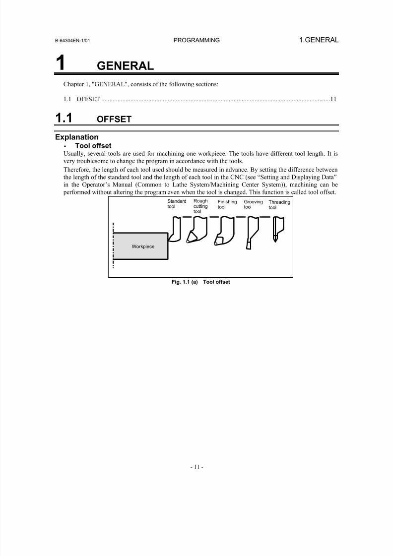
Explanation- Tool offsetUsually, several tools are used for machining one workpiece. The tools have different tool length. It is
very troublesome to change the program in accordance with the tools.
Therefore, the length of each tool used should be measured in advance. By setting the difference between
the length of the standard tool and the length of each tool in the CNC (see “Setting and Displaying Data”
in the Operator’s Manual (Common to Lathe System/Machining Center System)), machining can be
performed without altering the program even when the tool is changed. This function is called tool offset.
Workpiece
Standardtool
Roughcuttingtool
Finishingtool
Groovingtool
Threadingtool
Fig. 1.1 (a) Tool offset
8/16/2019 Manual Operacion para FANUC
http://slidepdf.com/reader/full/manual-operacion-para-fanuc 30/435
PROGRAMMING B-64304EN-1/01
- 12 -
2. PREPARATORY FUNCTION(G FUNCTION)
2 PREPARATORY FUNCTION(G FUNCTION)
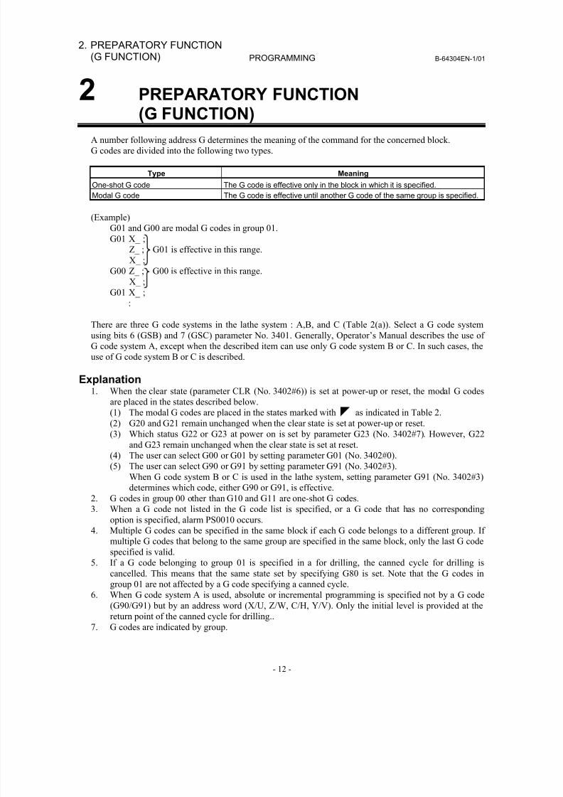
A number following address G determines the meaning of the command for the concerned block.
G codes are divided into the following two types.
Type Meaning
One-shot G code The G code is effective only in the block in which it is specified.
Modal G code The G code is effective until another G code of the same group is specified.
(Example)
G01 and G00 are modal G codes in group 01.
G01 X_ ;
Z_ ; G01 is effective in this range.X_ ;
G00 Z_ ; G00 is effective in this range.
X_ ;
G01 X_ ;
:
There are three G code systems in the lathe system : A,B, and C (Table 2(a)). Select a G code system
using bits 6 (GSB) and 7 (GSC) parameter No. 3401. Generally, Operator’s Manual describes the use of
G code system A, except when the described item can use only G code system B or C. In such cases, the
use of G code system B or C is described.
Explanation1. When the clear state (parameter CLR (No. 3402#6)) is set at power-up or reset, the modal G codes
are placed in the states described below.
(1) The modal G codes are placed in the states marked with as indicated in Table 2.
(2) G20 and G21 remain unchanged when the clear state is set at power-up or reset.
(3) Which status G22 or G23 at power on is set by parameter G23 (No. 3402#7). However, G22
and G23 remain unchanged when the clear state is set at reset.
(4) The user can select G00 or G01 by setting parameter G01 (No. 3402#0).
(5) The user can select G90 or G91 by setting parameter G91 (No. 3402#3).
When G code system B or C is used in the lathe system, setting parameter G91 (No. 3402#3)
determines which code, either G90 or G91, is effective.
2. G codes in group 00 other than G10 and G11 are one-shot G codes.3. When a G code not listed in the G code list is specified, or a G code that has no corresponding
option is specified, alarm PS0010 occurs.
4. Multiple G codes can be specified in the same block if each G code belongs to a different group. If
multiple G codes that belong to the same group are specified in the same block, only the last G code
specified is valid.
5. If a G code belonging to group 01 is specified in a for drilling, the canned cycle for drilling is
cancelled. This means that the same state set by specifying G80 is set. Note that the G codes in
group 01 are not affected by a G code specifying a canned cycle.
6. When G code system A is used, absolute or incremental programming is specified not by a G code
(G90/G91) but by an address word (X/U, Z/W, C/H, Y/V). Only the initial level is provided at the
return point of the canned cycle for drilling..
7. G codes are indicated by group.
8/16/2019 Manual Operacion para FANUC
http://slidepdf.com/reader/full/manual-operacion-para-fanuc 31/435
B-64304EN-1/01 PROGRAMMING
- 13 -
2.PREPARATORY FUNCTION(G FUNCTION)
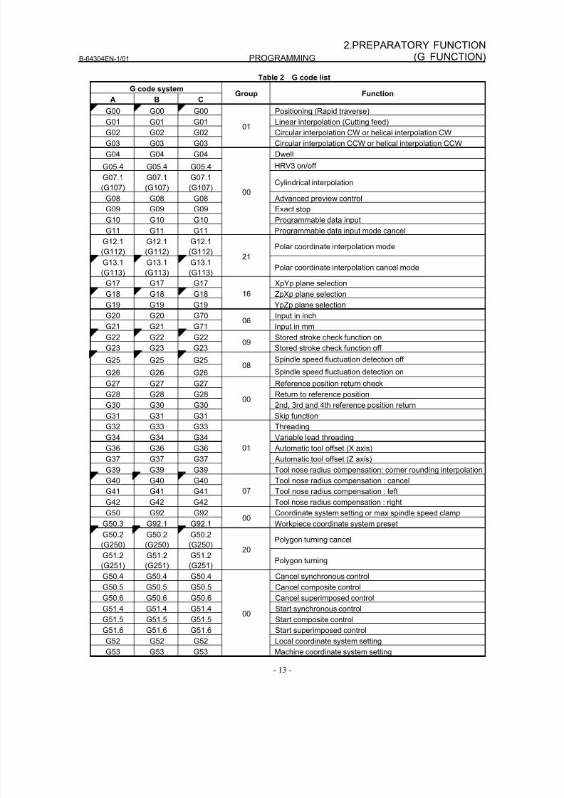
Table 2 G code list
G code system
A B CGroup Function
G00 G00 G00 Positioning (Rapid traverse)
G01 G01 G01 Linear interpolation (Cutting feed)G02 G02 G02 Circular interpolation CW or helical interpolation CW
G03 G03 G03
01
Circular interpolation CCW or helical interpolation CCW
G04 G04 G04 Dwell
G05.4 G05.4 G05.4 HRV3 on/off
G07.1
(G107)
G07.1
(G107)
G07.1
(G107)Cylindrical interpolation
G08 G08 G08 Advanced preview control
G09 G09 G09 Exact stop
G10 G10 G10 Programmable data input
G11 G11 G11
00
Programmable data input mode cancel
G12.1
(G112)
G12.1
(G112)
G12.1
(G112) Polar coordinate interpolation modeG13.1
(G113)
G13.1
(G113)
G13.1
(G113)
21
Polar coordinate interpolation cancel mode
G17 G17 G17 XpYp plane selection
G18 G18 G18 ZpXp plane selection
G19 G19 G19
16
YpZp plane selection
G20 G20 G70 Input in inch
G21 G21 G7106
Input in mm
G22 G22 G22 Stored stroke check function on
G23 G23 G2309
Stored stroke check function off
G25 G25 G25 Spindle speed fluctuation detection off
G26 G26 G26
08Spindle speed fluctuation detection on
G27 G27 G27 Reference position return check
G28 G28 G28 Return to reference position
G30 G30 G30 2nd, 3rd and 4th reference position return
G31 G31 G31
00
Skip function
G32 G33 G33 Threading
G34 G34 G34 Variable lead threading
G36 G36 G36 Automatic tool offset (X axis)
G37 G37 G37 Automatic tool offset (Z axis)
G39 G39 G39
01
Tool nose radius compensation: corner rounding interpolation
G40 G40 G40 Tool nose radius compensation : cancel
G41 G41 G41 Tool nose radius compensation : left
G42 G42 G42
07
Tool nose radius compensation : rightG50 G92 G92 Coordinate system setting or max spindle speed clamp
G50.3 G92.1 G92.100
Workpiece coordinate system preset
G50.2
(G250)
G50.2
(G250)
G50.2
(G250)Polygon turning cancel
G51.2
(G251)
G51.2
(G251)
G51.2
(G251)
20
Polygon turning
G50.4 G50.4 G50.4 Cancel synchronous control
G50.5 G50.5 G50.5 Cancel composite control
G50.6 G50.6 G50.6 Cancel superimposed control
G51.4 G51.4 G51.4 Start synchronous control
G51.5 G51.5 G51.5 Start composite control
G51.6 G51.6 G51.6 Start superimposed control
G52 G52 G52 Local coordinate system setting
G53 G53 G53
00
Machine coordinate system setting
8/16/2019 Manual Operacion para FANUC
http://slidepdf.com/reader/full/manual-operacion-para-fanuc 32/435
PROGRAMMING B-64304EN-1/01
- 14 -
2. PREPARATORY FUNCTION(G FUNCTION)
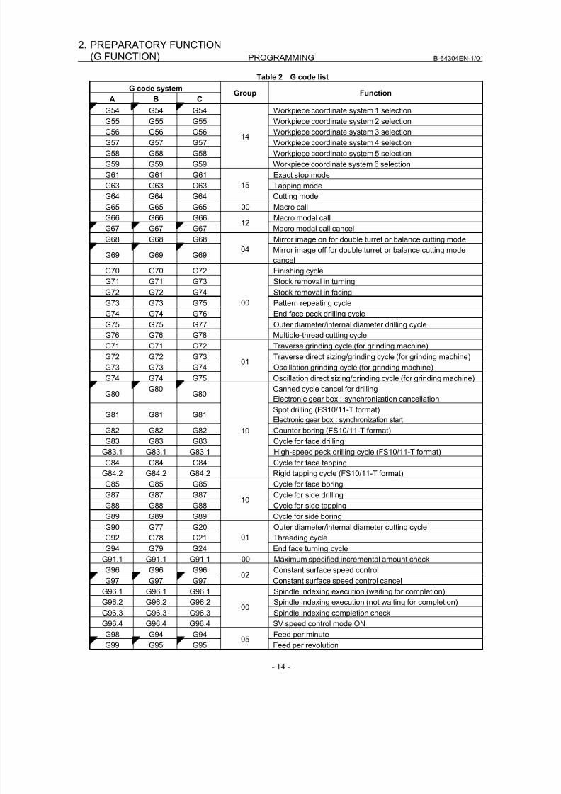
Table 2 G code list
G code system
A B CGroup Function
G54 G54 G54 Workpiece coordinate system 1 selection
G55 G55 G55 Workpiece coordinate system 2 selectionG56 G56 G56 Workpiece coordinate system 3 selection
G57 G57 G57 Workpiece coordinate system 4 selection
G58 G58 G58 Workpiece coordinate system 5 selection
G59 G59 G59
14
Workpiece coordinate system 6 selection
G61 G61 G61 Exact stop mode
G63 G63 G63 Tapping mode
G64 G64 G64
15
Cutting mode
G65 G65 G65 00 Macro call
G66 G66 G66 Macro modal call
G67 G67 G6712
Macro modal call cancel
G68 G68 G68 Mirror image on for double turret or balance cutting mode
G69 G69 G69 04 Mirror image off for double turret or balance cutting modecancel
G70 G70 G72 Finishing cycle
G71 G71 G73 Stock removal in turning
G72 G72 G74 Stock removal in facing
G73 G73 G75 Pattern repeating cycle
G74 G74 G76 End face peck drilling cycle
G75 G75 G77 Outer diameter/internal diameter drilling cycle
G76 G76 G78
00
Multiple-thread cutting cycle
G71 G71 G72 Traverse grinding cycle (for grinding machine)
G72 G72 G73 Traverse direct sizing/grinding cycle (for grinding machine)
G73 G73 G74 Oscillation grinding cycle (for grinding machine)
G74 G74 G75
01
Oscillation direct sizing/grinding cycle (for grinding machine)
G80G80
G80Canned cycle cancel for drilling
Electronic gear box : synchronization cancellation
G81 G81 G81Spot drilling (FS10/11-T format)
Electronic gear box : synchronization start
G82 G82 G82 Counter boring (FS10/11-T format)
G83 G83 G83 Cycle for face drilling
G83.1 G83.1 G83.1 High-speed peck drilling cycle (FS10/11-T format)
G84 G84 G84 Cycle for face tapping
G84.2 G84.2 G84.2
10
Rigid tapping cycle (FS10/11-T format)
G85 G85 G85 Cycle for face boring
G87 G87 G87 Cycle for side drillingG88 G88 G88 Cycle for side tapping
G89 G89 G89
10
Cycle for side boring
G90 G77 G20 Outer diameter/internal diameter cutting cycle
G92 G78 G21 Threading cycle
G94 G79 G24
01
End face turning cycle
G91.1 G91.1 G91.1 00 Maximum specified incremental amount check
G96 G96 G96 Constant surface speed control
G97 G97 G9702
Constant surface speed control cancel
G96.1 G96.1 G96.1 Spindle indexing execution (waiting for completion)
G96.2 G96.2 G96.2 Spindle indexing execution (not waiting for completion)
G96.3 G96.3 G96.3 Spindle indexing completion check
G96.4 G96.4 G96.4
00
SV speed control mode ONG98 G94 G94 Feed per minute
G99 G95 G9505
Feed per revolution

8/16/2019 Manual Operacion para FANUC
http://slidepdf.com/reader/full/manual-operacion-para-fanuc 33/435
B-64304EN-1/01 PROGRAMMING
- 15 -
2.PREPARATORY FUNCTION(G FUNCTION)
Table 2 G code list
G code system
A B CGroup Function
- G90 G90 Absolute programming
- G91 G91
03
Incremental programming- G98 G98 Canned cycle : return to initial level
- G99 G9911
Canned cycle : return to R point level
8/16/2019 Manual Operacion para FANUC
http://slidepdf.com/reader/full/manual-operacion-para-fanuc 34/435
3.INTERPOLATION FUNCTION PROGRAMMING B-64304EN-1/01
- 16 -
3 INTERPOLATION FUNCTION
Chapter 3, "INTERPOLATION FUNCTION", consists of the following sections:
3.1 POLAR COORDINATE INTERPOLATION (G12.1, G13.1)...........................................................16
3.2 CONSTANT LEAD THREADING (G32) .........................................................................................23
3.3 VARIABLE LEAD THREADING (G34) ..........................................................................................26
3.4 CONTINUOUS THREADING...........................................................................................................27
3.5 MULTIPLE THREADING.................................................................................................................27
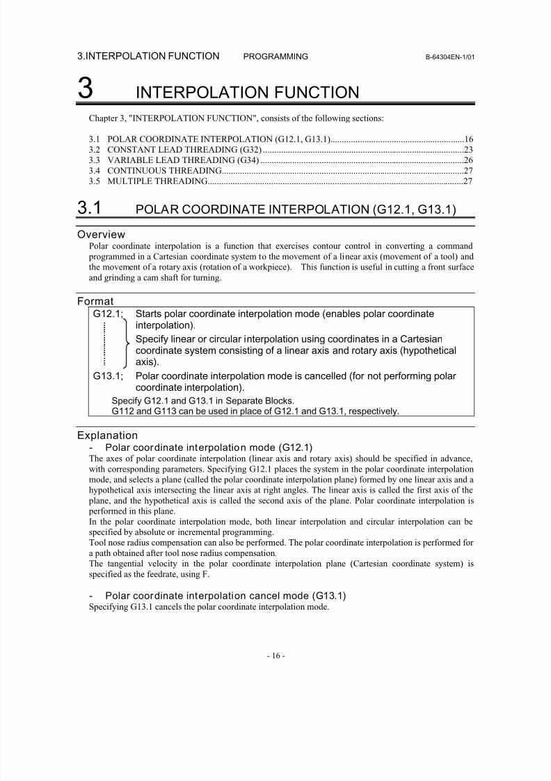
3.1 POLAR COORDINATE INTERPOLATION (G12.1, G13.1)
Overview
Polar coordinate interpolation is a function that exercises contour control in converting a command programmed in a Cartesian coordinate system to the movement of a linear axis (movement of a tool) and
the movement of a rotary axis (rotation of a workpiece). This function is useful in cutting a front surface
and grinding a cam shaft for turning.
FormatG12.1; Starts polar coordinate interpolation mode (enables polar coordinate
interpolation).
Specify linear or circular interpolation using coordinates in a Cartesiancoordinate system consisting of a linear axis and rotary axis (hypotheticalaxis).
G13.1; Polar coordinate interpolation mode is cancelled (for not performing polarcoordinate interpolation).
Specify G12.1 and G13.1 in Separate Blocks.G112 and G113 can be used in place of G12.1 and G13.1, respectively.
Explanation- Polar coordinate interpolation mode (G12.1)The axes of polar coordinate interpolation (linear axis and rotary axis) should be specified in advance,
with corresponding parameters. Specifying G12.1 places the system in the polar coordinate interpolation
mode, and selects a plane (called the polar coordinate interpolation plane) formed by one linear axis and a
hypothetical axis intersecting the linear axis at right angles. The linear axis is called the first axis of the plane, and the hypothetical axis is called the second axis of the plane. Polar coordinate interpolation is
performed in this plane.
In the polar coordinate interpolation mode, both linear interpolation and circular interpolation can be
specified by absolute or incremental programming.
Tool nose radius compensation can also be performed. The polar coordinate interpolation is performed for
a path obtained after tool nose radius compensation.
The tangential velocity in the polar coordinate interpolation plane (Cartesian coordinate system) is
specified as the feedrate, using F.
- Polar coordinate interpolation cancel mode (G13.1)Specifying G13.1 cancels the polar coordinate interpolation mode.
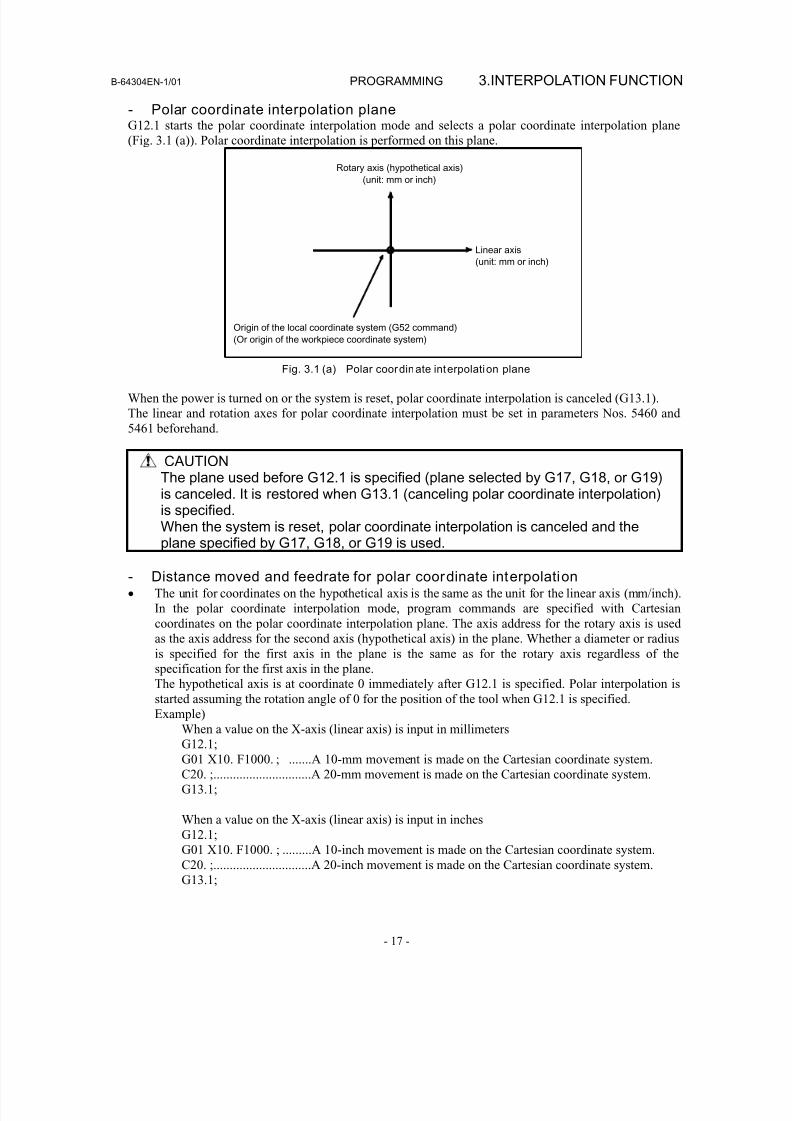
8/16/2019 Manual Operacion para FANUC
http://slidepdf.com/reader/full/manual-operacion-para-fanuc 35/435
B-64304EN-1/01 PROGRAMMING 3.INTERPOLATION FUNCTION
- 17 -
- Polar coordinate interpolation planeG12.1 starts the polar coordinate interpolation mode and selects a polar coordinate interpolation plane
(Fig. 3.1 (a)). Polar coordinate interpolation is performed on this plane.
Rotary axis (hypothetical axis)
(unit: mm or inch)
Linear axis
(unit: mm or inch)
Origin of the local coordinate system (G52 command)
(Or origin of the workpiece coordinate system)
Fig. 3.1 (a) Polar coordinate interpolation plane
When the power is turned on or the system is reset, polar coordinate interpolation is canceled (G13.1).
The linear and rotation axes for polar coordinate interpolation must be set in parameters Nos. 5460 and
5461 beforehand.
CAUTIONThe plane used before G12.1 is specified (plane selected by G17, G18, or G19)is canceled. It is restored when G13.1 (canceling polar coordinate interpolation)is specified.
When the system is reset, polar coordinate interpolation is canceled and theplane specified by G17, G18, or G19 is used.
- Distance moved and feedrate for polar coordinate interpolation• The unit for coordinates on the hypothetical axis is the same as the unit for the linear axis (mm/inch).
In the polar coordinate interpolation mode, program commands are specified with Cartesian
coordinates on the polar coordinate interpolation plane. The axis address for the rotary axis is used
as the axis address for the second axis (hypothetical axis) in the plane. Whether a diameter or radius
is specified for the first axis in the plane is the same as for the rotary axis regardless of the
specification for the first axis in the plane.
The hypothetical axis is at coordinate 0 immediately after G12.1 is specified. Polar interpolation is
started assuming the rotation angle of 0 for the position of the tool when G12.1 is specified.Example)
When a value on the X-axis (linear axis) is input in millimeters
G12.1;
G01 X10. F1000. ; .......A 10-mm movement is made on the Cartesian coordinate system.
C20. ;..............................A 20-mm movement is made on the Cartesian coordinate system.
G13.1;
When a value on the X-axis (linear axis) is input in inches
G12.1;
G01 X10. F1000. ; .........A 10-inch movement is made on the Cartesian coordinate system.
C20. ;..............................A 20-inch movement is made on the Cartesian coordinate system.
G13.1;
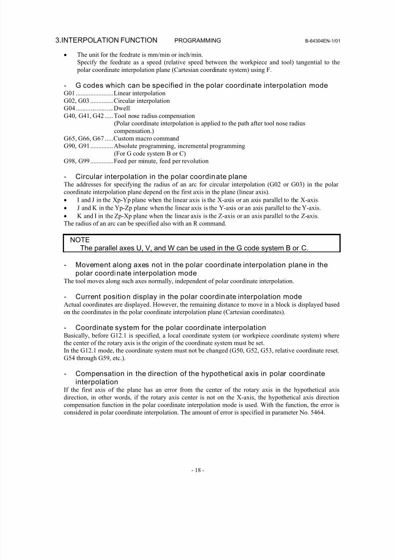
8/16/2019 Manual Operacion para FANUC
http://slidepdf.com/reader/full/manual-operacion-para-fanuc 36/435
3.INTERPOLATION FUNCTION PROGRAMMING B-64304EN-1/01
- 18 -
• The unit for the feedrate is mm/min or inch/min.
Specify the feedrate as a speed (relative speed between the workpiece and tool) tangential to the
polar coordinate interpolation plane (Cartesian coordinate system) using F.
- G codes which can be specified in the polar coordinate interpolation modeG01.......................Linear interpolation
G02, G03 ..............Circular interpolation
G04....................... Dwell
G40, G41, G42 .....Tool nose radius compensation
(Polar coordinate interpolation is applied to the path after tool nose radius
compensation.)
G65, G66, G67 .....Custom macro command
G90, G91..............Absolute programming, incremental programming
(For G code system B or C)
G98, G99..............Feed per minute, feed per revolution
- Circular interpolation in the polar coordinate planeThe addresses for specifying the radius of an arc for circular interpolation (G02 or G03) in the polar
coordinate interpolation plane depend on the first axis in the plane (linear axis).
• I and J in the Xp-Yp plane when the linear axis is the X-axis or an axis parallel to the X-axis.
• J and K in the Yp-Zp plane when the linear axis is the Y-axis or an axis parallel to the Y-axis.
• K and I in the Zp-Xp plane when the linear axis is the Z-axis or an axis parallel to the Z-axis.
The radius of an arc can be specified also with an R command.
NOTEThe parallel axes U, V, and W can be used in the G code system B or C.
- Movement along axes not in the polar coordinate interpolation plane in thepolar coordinate interpolation mode
The tool moves along such axes normally, independent of polar coordinate interpolation.
- Current position display in the polar coordinate interpolation modeActual coordinates are displayed. However, the remaining distance to move in a block is displayed based
on the coordinates in the polar coordinate interpolation plane (Cartesian coordinates).
- Coordinate system for the polar coordinate interpolationBasically, before G12.1 is specified, a local coordinate system (or workpiece coordinate system) where
the center of the rotary axis is the origin of the coordinate system must be set.
In the G12.1 mode, the coordinate system must not be changed (G50, G52, G53, relative coordinate reset,G54 through G59, etc.).
- Compensation in the direction of the hypothetical axis in polar coordinateinterpolation
If the first axis of the plane has an error from the center of the rotary axis in the hypothetical axis
direction, in other words, if the rotary axis center is not on the X-axis, the hypothetical axis direction
compensation function in the polar coordinate interpolation mode is used. With the function, the error is
considered in polar coordinate interpolation. The amount of error is specified in parameter No. 5464.
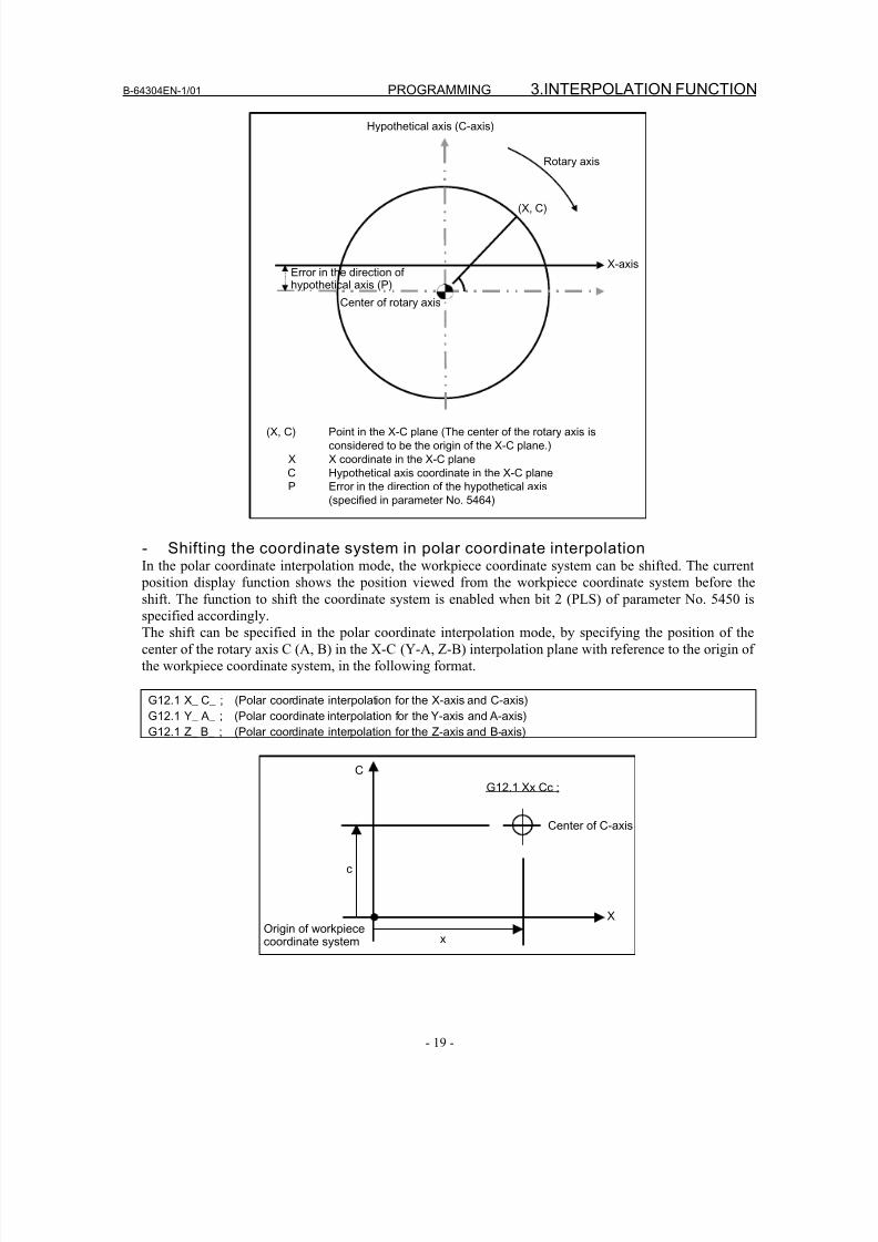
8/16/2019 Manual Operacion para FANUC
http://slidepdf.com/reader/full/manual-operacion-para-fanuc 37/435
B-64304EN-1/01 PROGRAMMING 3.INTERPOLATION FUNCTION
- 19 -
(X, C)
Hypothetical axis (C-axis)
Error in the direction ofhypothetical axis (P)
Center of rotary axis
X-axis
Rotary axis
(X, C) Point in the X-C plane (The center of the rotary axis is
considered to be the origin of the X-C plane.)
X X coordinate in the X-C plane
C Hypothetical axis coordinate in the X-C plane
P Error in the direction of the hypothetical axis
(specified in parameter No. 5464)
- Shifting the coordinate system in polar coordinate interpolationIn the polar coordinate interpolation mode, the workpiece coordinate system can be shifted. The current
position display function shows the position viewed from the workpiece coordinate system before theshift. The function to shift the coordinate system is enabled when bit 2 (PLS) of parameter No. 5450 is
specified accordingly.
The shift can be specified in the polar coordinate interpolation mode, by specifying the position of the
center of the rotary axis C (A, B) in the X-C (Y-A, Z-B) interpolation plane with reference to the origin of
the workpiece coordinate system, in the following format.
G12.1 X_ C_ ; (Polar coordinate interpolation for the X-axis and C-axis)
G12.1 Y_ A_ ; (Polar coordinate interpolation for the Y-axis and A-axis)
G12.1 Z_ B_ ; (Polar coordinate interpolation for the Z-axis and B-axis)
X
C
x
c
Center of C-axis
G12.1 Xx Cc ;
Origin of workpiececoordinate system
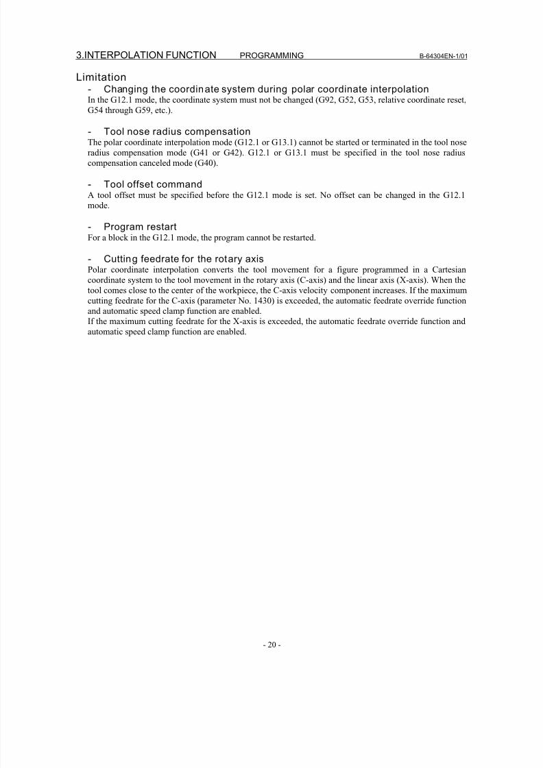
8/16/2019 Manual Operacion para FANUC
http://slidepdf.com/reader/full/manual-operacion-para-fanuc 38/435
3.INTERPOLATION FUNCTION PROGRAMMING B-64304EN-1/01
- 20 -
Limitation- Changing the coordinate system during polar coordinate interpolationIn the G12.1 mode, the coordinate system must not be changed (G92, G52, G53, relative coordinate reset,
G54 through G59, etc.).
- Tool nose radius compensationThe polar coordinate interpolation mode (G12.1 or G13.1) cannot be started or terminated in the tool nose
radius compensation mode (G41 or G42). G12.1 or G13.1 must be specified in the tool nose radius
compensation canceled mode (G40).
- Tool offset commandA tool offset must be specified before the G12.1 mode is set. No offset can be changed in the G12.1
mode.
- Program restart
For a block in the G12.1 mode, the program cannot be restarted.
- Cutting feedrate for the rotary axisPolar coordinate interpolation converts the tool movement for a figure programmed in a Cartesian
coordinate system to the tool movement in the rotary axis (C-axis) and the linear axis (X-axis). When the
tool comes close to the center of the workpiece, the C-axis velocity component increases. If the maximum
cutting feedrate for the C-axis (parameter No. 1430) is exceeded, the automatic feedrate override function
and automatic speed clamp function are enabled.
If the maximum cutting feedrate for the X-axis is exceeded, the automatic feedrate override function and
automatic speed clamp function are enabled.
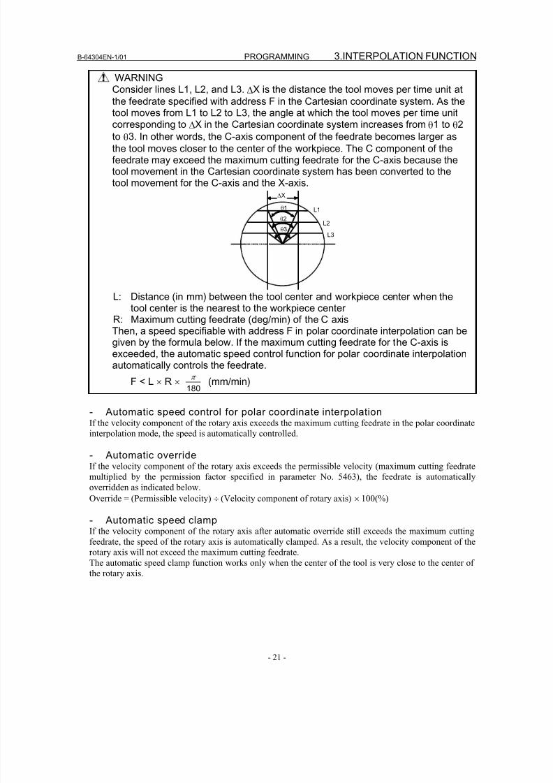
8/16/2019 Manual Operacion para FANUC
http://slidepdf.com/reader/full/manual-operacion-para-fanuc 39/435
B-64304EN-1/01 PROGRAMMING 3.INTERPOLATION FUNCTION
- 21 -
WARNINGConsider lines L1, L2, and L3. ΔX is the distance the tool moves per time unit at
the feedrate specified with address F in the Cartesian coordinate system. As thetool moves from L1 to L2 to L3, the angle at which the tool moves per time unit
corresponding to ΔX in the Cartesian coordinate system increases from θ1 to θ2to θ3. In other words, the C-axis component of the feedrate becomes larger as
the tool moves closer to the center of the workpiece. The C component of thefeedrate may exceed the maximum cutting feedrate for the C-axis because thetool movement in the Cartesian coordinate system has been converted to thetool movement for the C-axis and the X-axis.
L1
L2
L3 θ3
θ2
θ1
ΔX
L: Distance (in mm) between the tool center and workpiece center when thetool center is the nearest to the workpiece center
R: Maximum cutting feedrate (deg/min) of the C axisThen, a speed specifiable with address F in polar coordinate interpolation can begiven by the formula below. If the maximum cutting feedrate for the C-axis isexceeded, the automatic speed control function for polar coordinate interpolation
automatically controls the feedrate.F < L × R ×
180
π
(mm/min)
- Automatic speed control for polar coordinate interpolationIf the velocity component of the rotary axis exceeds the maximum cutting feedrate in the polar coordinate
interpolation mode, the speed is automatically controlled.
- Automatic overrideIf the velocity component of the rotary axis exceeds the permissible velocity (maximum cutting feedrate
multiplied by the permission factor specified in parameter No. 5463), the feedrate is automatically
overridden as indicated below.Override = (Permissible velocity) ÷ (Velocity component of rotary axis) × 100(%)
- Automatic speed clampIf the velocity component of the rotary axis after automatic override still exceeds the maximum cutting
feedrate, the speed of the rotary axis is automatically clamped. As a result, the velocity component of the
rotary axis will not exceed the maximum cutting feedrate.
The automatic speed clamp function works only when the center of the tool is very close to the center of
the rotary axis.
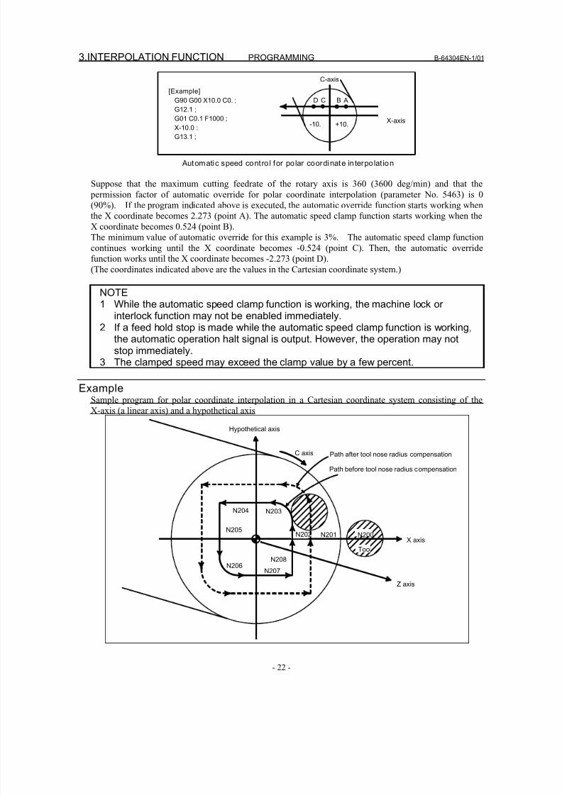
8/16/2019 Manual Operacion para FANUC
http://slidepdf.com/reader/full/manual-operacion-para-fanuc 40/435
3.INTERPOLATION FUNCTION PROGRAMMING B-64304EN-1/01
- 22 -
C-axis
ABCD
X-axis-10. +10.
[Example]
G90 G00 X10.0 C0. ;
G12.1 ;
G01 C0.1 F1000 ;
X-10.0 :
G13.1 ;
Automatic speed contro l for polar coordinate interpolat ion
Suppose that the maximum cutting feedrate of the rotary axis is 360 (3600 deg/min) and that the
permission factor of automatic override for polar coordinate interpolation (parameter No. 5463) is 0
(90%). If the program indicated above is executed, the automatic override function starts working when
the X coordinate becomes 2.273 (point A). The automatic speed clamp function starts working when the
X coordinate becomes 0.524 (point B).
The minimum value of automatic override for this example is 3%. The automatic speed clamp function
continues working until the X coordinate becomes -0.524 (point C). Then, the automatic overridefunction works until the X coordinate becomes -2.273 (point D).
(The coordinates indicated above are the values in the Cartesian coordinate system.)
NOTE1 While the automatic speed clamp function is working, the machine lock or
interlock function may not be enabled immediately.2 If a feed hold stop is made while the automatic speed clamp function is working,
the automatic operation halt signal is output. However, the operation may notstop immediately.
3 The clamped speed may exceed the clamp value by a few percent.
ExampleSample program for polar coordinate interpolation in a Cartesian coordinate system consisting of the
X-axis (a linear axis) and a hypothetical axis
N204
N205
N206
N203
N202 N201
N208
N207
N200
Tool
C axis
Hypothetical axis
Path after tool nose radius compensation
Path before tool nose radius compensation
X axis
Z axis
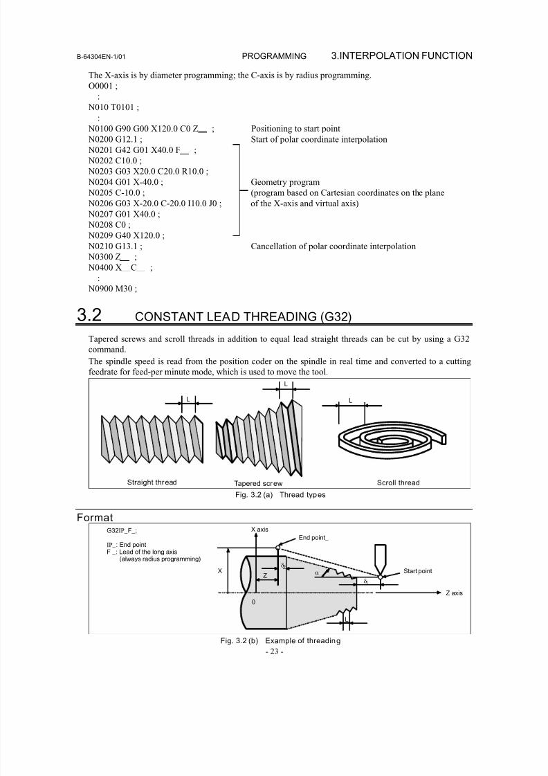
8/16/2019 Manual Operacion para FANUC
http://slidepdf.com/reader/full/manual-operacion-para-fanuc 41/435
B-64304EN-1/01 PROGRAMMING 3.INTERPOLATION FUNCTION
- 23 -
The X-axis is by diameter programming; the C-axis is by radius programming.
O0001 ;
:
N010 T0101 ;
: N0100 G90 G00 X120.0 C0 Z ; Positioning to start point
N0200 G12.1 ; Start of polar coordinate interpolation
N0201 G42 G01 X40.0 F ;
N0202 C10.0 ;
N0203 G03 X20.0 C20.0 R10.0 ;
N0204 G01 X-40.0 ; Geometry program
N0205 C-10.0 ; (program based on Cartesian coordinates on the plane
N0206 G03 X-20.0 C-20.0 I10.0 J0 ; of the X-axis and virtual axis)
N0207 G01 X40.0 ;
N0208 C0 ;
N0209 G40 X120.0 ;
N0210 G13.1 ; Cancellation of polar coordinate interpolation N0300 Z
;
N0400 X C ;
:
N0900 M30 ;
3.2 CONSTANT LEAD THREADING (G32)
Tapered screws and scroll threads in addition to equal lead straight threads can be cut by using a G32
command.
The spindle speed is read from the position coder on the spindle in real time and converted to a cuttingfeedrate for feed-per minute mode, which is used to move the tool.
L
Straight thread
L
L
Tapered screw Scroll thread
Fig. 3.2 (a) Thread types
Format
X
X axis
Z
δ2 α Start point
L
δ1
End point_
0
Z axis
G32IP _F_;
IP _: End pointF _: Lead of the long axis
(always radius programming)
Fig. 3.2 (b) Example of threading
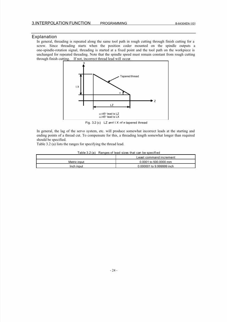
8/16/2019 Manual Operacion para FANUC
http://slidepdf.com/reader/full/manual-operacion-para-fanuc 42/435
3.INTERPOLATION FUNCTION PROGRAMMING B-64304EN-1/01
- 24 -
ExplanationIn general, threading is repeated along the same tool path in rough cutting through finish cutting for a
screw. Since threading starts when the position coder mounted on the spindle outputs a
one-spindle-rotation signal, threading is started at a fixed point and the tool path on the workpiece isunchanged for repeated threading. Note that the spindle speed must remain constant from rough cutting
through finish cutting. If not, incorrect thread lead will occur.X
Tapered thread
LX
α
LZZ
α≤45° lead is LZα≥45° lead is LX
Fig. 3.2 (c) LZ and LX of a tapered thread
In general, the lag of the servo system, etc. will produce somewhat incorrect leads at the starting and
ending points of a thread cut. To compensate for this, a threading length somewhat longer than required
should be specified.
Table 3.2 (a) lists the ranges for specifying the thread lead.
Table 3.2 (a) Ranges of lead sizes that can be specifi ed
Least command increment
Metric input 0.0001 to 500.0000 mm
Inch input 0.000001 to 9.999999 inch
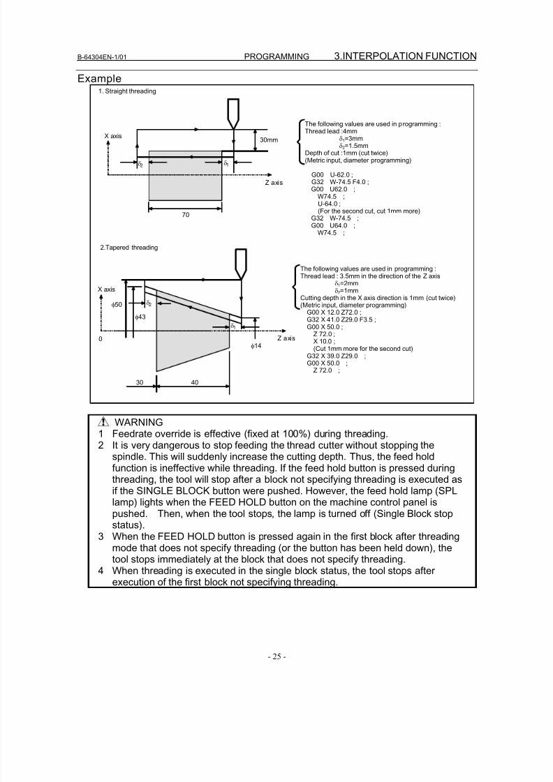
8/16/2019 Manual Operacion para FANUC
http://slidepdf.com/reader/full/manual-operacion-para-fanuc 43/435
B-64304EN-1/01 PROGRAMMING 3.INTERPOLATION FUNCTION
- 25 -
Example
Z axis
X axis
δ2 δ1
30mm
70
The following values are used in programming :Thread lead :4mm
δ1=3mmδ2=1.5mm
Depth of cut :1mm (cut twice)(Metric input, diameter programming)
G00 U-62.0 ; G32 W-74.5 F4.0 ; G00 U62.0 ; W74.5 ; U-64.0 ; (For the second cut, cut 1mm more) G32 W-74.5 ; G00 U64.0 ; W74.5 ;
1. Straight threading
Z axis
X axis
δ2
δ1
40
The following values are used in programming :Thread lead : 3.5mm in the direction of the Z axis
δ1=2mmδ2=1mm
Cutting depth in the X axis direction is 1mm (cut twice)(Metric input, diameter programming) G00 X 12.0 Z72.0 ; G32 X 41.0 Z29.0 F3.5 ; G00 X 50.0 ; Z 72.0 ; X 10.0 ; (Cut 1mm more for the second cut) G32 X 39.0 Z29.0 ; G00 X 50.0 ;
Z 72.0 ;
30
0
φ50
φ43
φ14
2.Tapered threading
WARNING1 Feedrate override is effective (fixed at 100%) during threading.2 It is very dangerous to stop feeding the thread cutter without stopping the
spindle. This will suddenly increase the cutting depth. Thus, the feed holdfunction is ineffective while threading. If the feed hold button is pressed duringthreading, the tool will stop after a block not specifying threading is executed as
if the SINGLE BLOCK button were pushed. However, the feed hold lamp (SPLlamp) lights when the FEED HOLD button on the machine control panel ispushed. Then, when the tool stops, the lamp is turned off (Single Block stopstatus).
3 When the FEED HOLD button is pressed again in the first block after threadingmode that does not specify threading (or the button has been held down), thetool stops immediately at the block that does not specify threading.
4 When threading is executed in the single block status, the tool stops afterexecution of the first block not specifying threading.
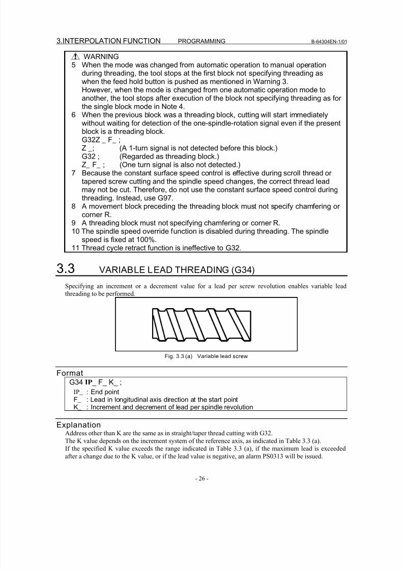
8/16/2019 Manual Operacion para FANUC
http://slidepdf.com/reader/full/manual-operacion-para-fanuc 44/435
3.INTERPOLATION FUNCTION PROGRAMMING B-64304EN-1/01
- 26 -
WARNING5 When the mode was changed from automatic operation to manual operation
during threading, the tool stops at the first block not specifying threading aswhen the feed hold button is pushed as mentioned in Warning 3.
However, when the mode is changed from one automatic operation mode toanother, the tool stops after execution of the block not specifying threading as forthe single block mode in Note 4.
6 When the previous block was a threading block, cutting will start immediatelywithout waiting for detection of the one-spindle-rotation signal even if the presentblock is a threading block.G32Z _ F_ ;Z _; (A 1-turn signal is not detected before this block.)G32 ; (Regarded as threading block.)Z_ F_ ; (One turn signal is also not detected.)
7 Because the constant surface speed control is effective during scroll thread or
tapered screw cutting and the spindle speed changes, the correct thread leadmay not be cut. Therefore, do not use the constant surface speed control duringthreading. Instead, use G97.
8 A movement block preceding the threading block must not specify chamfering orcorner R.
9 A threading block must not specifying chamfering or corner R.10 The spindle speed override function is disabled during threading. The spindle
speed is fixed at 100%.11 Thread cycle retract function is ineffective to G32.
3.3 VARIABLE LEAD THREADING (G34)
Specifying an increment or a decrement value for a lead per screw revolution enables variable lead
threading to be performed.
Fig. 3.3 (a) Variable lead screw
FormatG34 IP _ F_ K_ ;
IP _ : End pointF_ : Lead in longitudinal axis direction at the start pointK_ : Increment and decrement of lead per spindle revolution
ExplanationAddress other than K are the same as in straight/taper thread cutting with G32.
The K value depends on the increment system of the reference axis, as indicated in Table 3.3 (a).
If the specified K value exceeds the range indicated in Table 3.3 (a), if the maximum lead is exceededafter a change due to the K value, or if the lead value is negative, an alarm PS0313 will be issued.
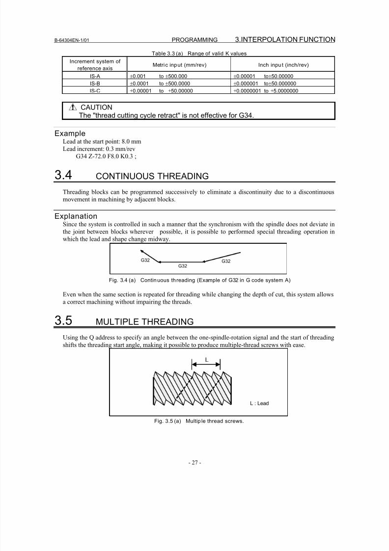
8/16/2019 Manual Operacion para FANUC
http://slidepdf.com/reader/full/manual-operacion-para-fanuc 45/435
B-64304EN-1/01 PROGRAMMING 3.INTERPOLATION FUNCTION
- 27 -
Table 3.3 (a) Range of valid K values
Increment system of
reference axisMetric input (mm/rev) Inch inpu t (inch/rev)
IS-A ±0.001 to ±500.000 ±0.00001 to±50.00000
IS-B ±0.0001 to ±500.0000 ±0.000001 to±50.000000
IS-C ±0.00001 to ±50.00000 ±0.0000001 to ±5.0000000
CAUTIONThe "thread cutting cycle retract" is not effective for G34.
ExampleLead at the start point: 8.0 mm
Lead increment: 0.3 mm/rev
G34 Z-72.0 F8.0 K0.3 ;
3.4 CONTINUOUS THREADING
Threading blocks can be programmed successively to eliminate a discontinuity due to a discontinuous
movement in machining by adjacent blocks.
ExplanationSince the system is controlled in such a manner that the synchronism with the spindle does not deviate in
the joint between blocks wherever possible, it is possible to performed special threading operation in
which the lead and shape change midway.
G32G32
G32
Fig. 3.4 (a) Continuous threading (Example of G32 in G code system A)
Even when the same section is repeated for threading while changing the depth of cut, this system allows
a correct machining without impairing the threads.
3.5 MULTIPLE THREADING
Using the Q address to specify an angle between the one-spindle-rotation signal and the start of threading
shifts the threading start angle, making it possible to produce multiple-thread screws with ease.
L
L : Lead
Fig. 3.5 (a) Multip le thread screws.
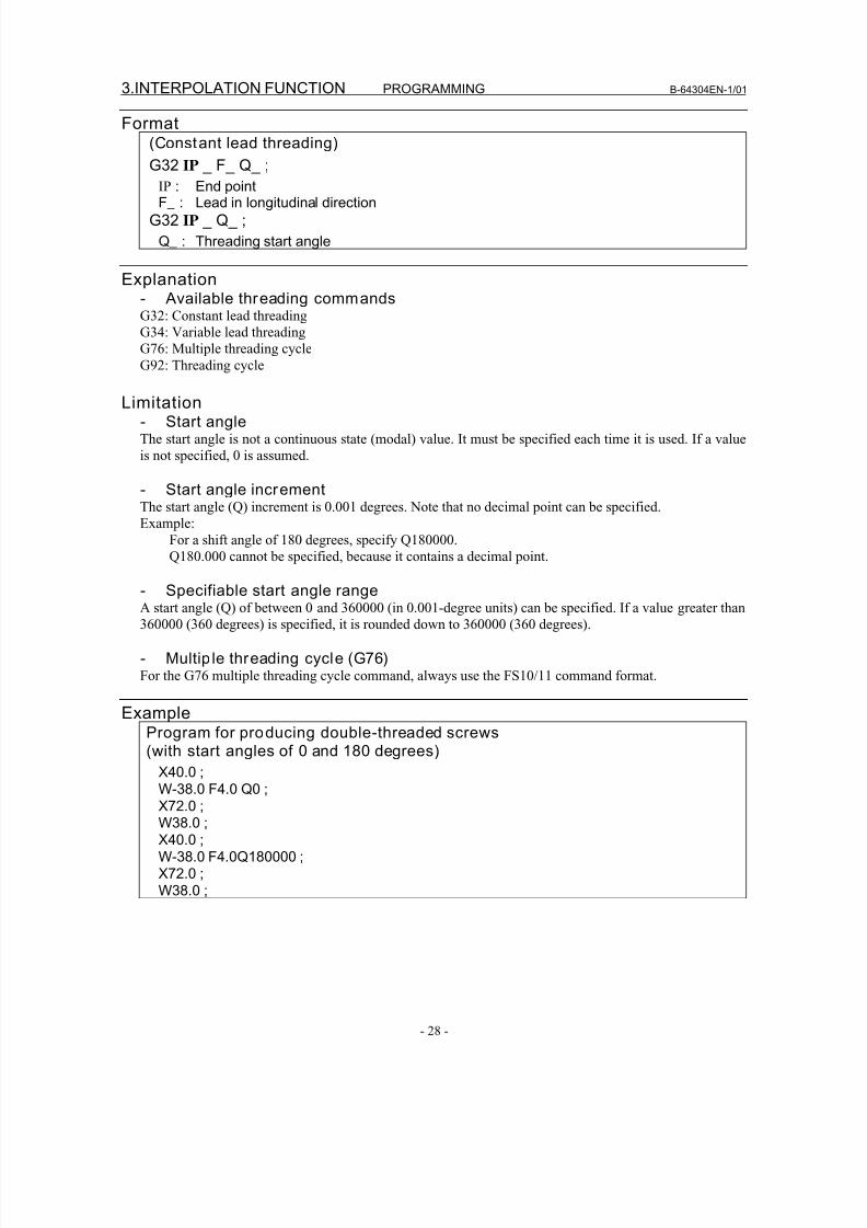
8/16/2019 Manual Operacion para FANUC
http://slidepdf.com/reader/full/manual-operacion-para-fanuc 46/435
3.INTERPOLATION FUNCTION PROGRAMMING B-64304EN-1/01
- 28 -
Format(Constant lead threading)
G32 IP _ F_ Q_ ;
IP : End pointF_ : Lead in longitudinal direction
G32 IP _ Q_ ;
Q_ : Threading start angle
Explanation- Available threading commandsG32: Constant lead threading
G34: Variable lead threading
G76: Multiple threading cycle
G92: Threading cycle
Limitation- Start angleThe start angle is not a continuous state (modal) value. It must be specified each time it is used. If a value
is not specified, 0 is assumed.
- Start angle incrementThe start angle (Q) increment is 0.001 degrees. Note that no decimal point can be specified.
Example:
For a shift angle of 180 degrees, specify Q180000.
Q180.000 cannot be specified, because it contains a decimal point.
- Specifiable start angle rangeA start angle (Q) of between 0 and 360000 (in 0.001-degree units) can be specified. If a value greater than
360000 (360 degrees) is specified, it is rounded down to 360000 (360 degrees).
- Multip le threading cycle (G76)For the G76 multiple threading cycle command, always use the FS10/11 command format.
ExampleProgram for producing double-threaded screws(with start angles of 0 and 180 degrees)
X40.0 ;W-38.0 F4.0 Q0 ;
X72.0 ;W38.0 ;
X40.0 ;
W-38.0 F4.0Q180000 ;X72.0 ;
W38.0 ;
8/16/2019 Manual Operacion para FANUC
http://slidepdf.com/reader/full/manual-operacion-para-fanuc 47/435
B-64304EN-1/01 PROGRAMMING
- 29 -
4.FUNCTIONS TO SIMPLIFYPROGRAMMING
4 FUNCTIONS TO SIMPLIFY PROGRAMMING
Chapter 4, "FUNCTIONS TO SIMPLIFY PROGRAMMING", consists of the following sections:
4.1 CANNED CYCLE (G90, G92, G94)..................................................................................................29
4.2 MULTIPLE REPETITIVE CANNED CYCLE (G70-G76) ...............................................................45
4.3 CANNED CYCLE FOR DRILLING .................................................................................................78
4.4 RIGID TAPPING................................................................................................................................91
4.5 CANNED GRINDING CYCLE (FOR GRINDING MACHINE)....................................................103
4.6 CHAMFERING AND CORNER R..................................................................................................103
4.7 MIRROR IMAGE FOR DOUBLE TURRET (G68, G69) ...............................................................117
4.8 DIRECT DRAWING DIMENSION PROGRAMMING .................................................................119
4.1 CANNED CYCLE (G90, G92, G94)There are three canned cycles : the outer diameter/internal diameter cutting canned cycle (G90), the
threading canned cycle (G92), and the end face turning canned cycle (G94).
NOTE1 Explanatory figures in this section use the ZX plane as the selected plane,
diameter programming for the X-axis, and radius programming for the Z-axis.When radius programming is used for the X-axis, change U/2 to U and X/2 to X.
2 A canned cycle can be performed on any plane (including parallel axes for planedefinition). When G-code system A is used, however, U, V, and W cannot be set
as a parallel axis.3 The direction of the length means the direction of the first axis on the plane asfollows:ZX plane: Z-axis directionYZ plane: Y-axis directionXY plane: X-axis direction
4 The direction of the end face means the direction of the second axis on theplane as follows:ZX plane: X-axis directionYZ plane: Z-axis directionXY plane: Y-axis direction
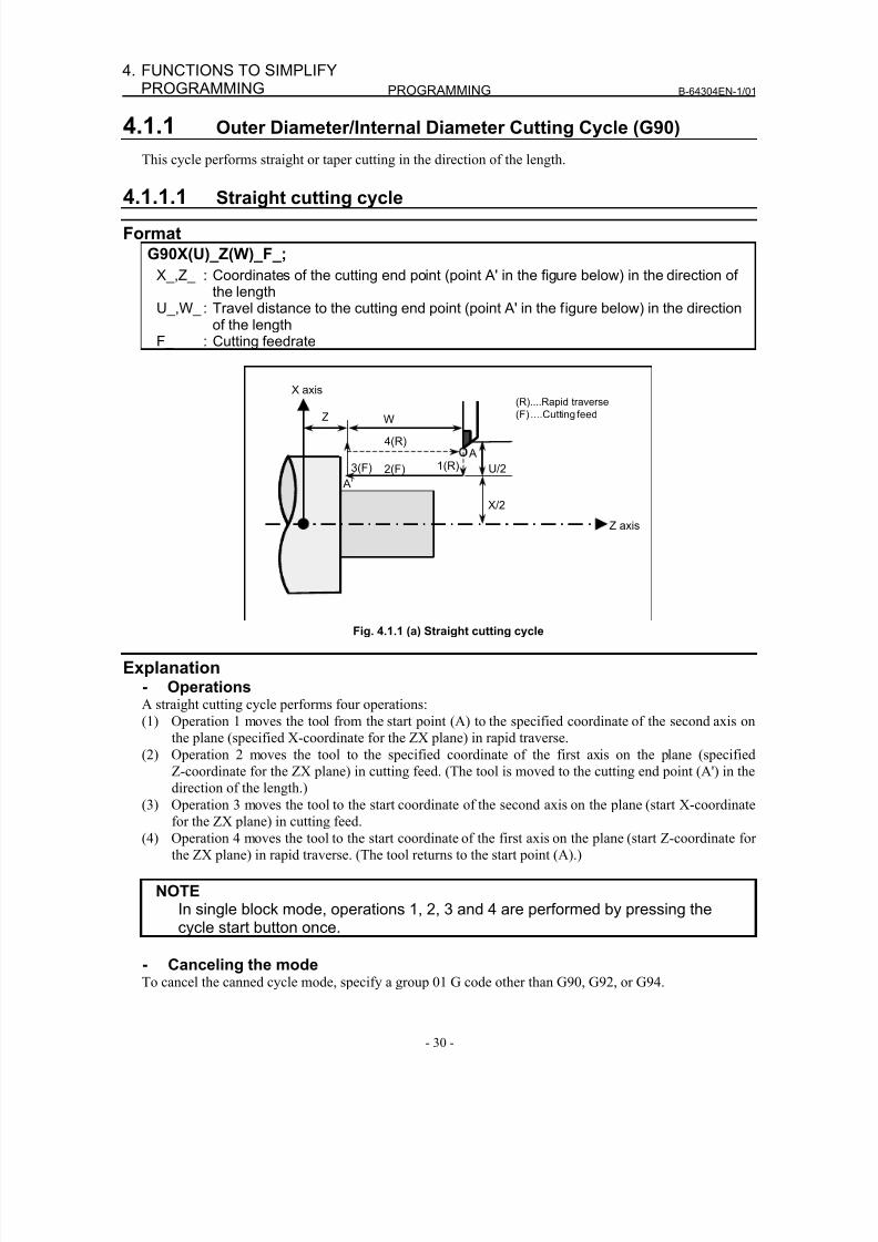
8/16/2019 Manual Operacion para FANUC
http://slidepdf.com/reader/full/manual-operacion-para-fanuc 48/435
PROGRAMMING B-64304EN-1/01
- 30 -
4. FUNCTIONS TO SIMPLIFYPROGRAMMING
4.1.1 Outer Diameter/Internal Diameter Cutting Cycle (G90)
This cycle performs straight or taper cutting in the direction of the length.
4.1.1.1 Straight cutting cycle
FormatG90X(U)_Z(W)_F_;
X_,Z_ : Coordinates of the cutting end point (point A' in the figure below) in the direction ofthe length
U_,W_ : Travel distance to the cutting end point (point A' in the figure below) in the directionof the length
F_ : Cutting feedrate
X/2
X axis
Z axis
2(F)3(F) 1(R)
4(R)
Z W
U/2
A’
A
(R)....Rapid traverse
(F) ....Cutting feed
Fig. 4.1.1 (a) Straight cutting cycle
Explanation- OperationsA straight cutting cycle performs four operations:
(1) Operation 1 moves the tool from the start point (A) to the specified coordinate of the second axis on
the plane (specified X-coordinate for the ZX plane) in rapid traverse.
(2) Operation 2 moves the tool to the specified coordinate of the first axis on the plane (specified
Z-coordinate for the ZX plane) in cutting feed. (The tool is moved to the cutting end point (A') in the
direction of the length.)
(3) Operation 3 moves the tool to the start coordinate of the second axis on the plane (start X-coordinate
for the ZX plane) in cutting feed.
(4) Operation 4 moves the tool to the start coordinate of the first axis on the plane (start Z-coordinate for
the ZX plane) in rapid traverse. (The tool returns to the start point (A).)
NOTEIn single block mode, operations 1, 2, 3 and 4 are performed by pressing thecycle start button once.
- Canceling the modeTo cancel the canned cycle mode, specify a group 01 G code other than G90, G92, or G94.
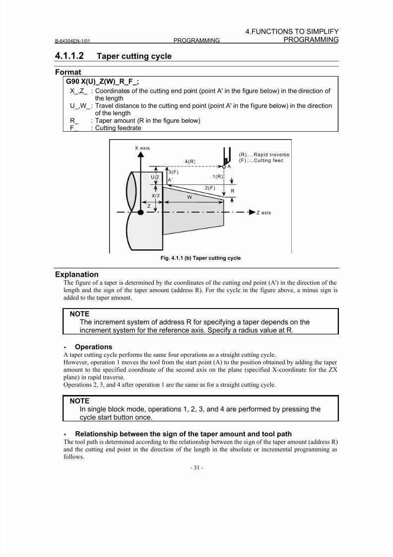
8/16/2019 Manual Operacion para FANUC
http://slidepdf.com/reader/full/manual-operacion-para-fanuc 49/435
B-64304EN-1/01 PROGRAMMING
- 31 -
4.FUNCTIONS TO SIMPLIFYPROGRAMMING
4.1.1.2 Taper cutting cycle
Format
G90 X(U)_Z(W)_R_F_;
X_,Z_ : Coordinates of the cutting end point (point A' in the figure below) in the direction ofthe length
U_,W_ : Travel distance to the cutting end point (point A' in the figure below) in the directionof the length
R_ : Taper amount (R in the figure below)F_ : Cutting feedrate
3(F)
X/2
4(R)
Z
U/2 1(R)
W
Z axis
2(F)R
X axis
A
A’
(R)....Rapid traverse
(F) ....Cutting feed
Fig. 4.1.1 (b) Taper cutting cycle
ExplanationThe figure of a taper is determined by the coordinates of the cutting end point (A') in the direction of the
length and the sign of the taper amount (address R). For the cycle in the figure above, a minus sign is
added to the taper amount.
NOTEThe increment system of address R for specifying a taper depends on theincrement system for the reference axis. Specify a radius value at R.
- OperationsA taper cutting cycle performs the same four operations as a straight cutting cycle.
However, operation 1 moves the tool from the start point (A) to the position obtained by adding the taper
amount to the specified coordinate of the second axis on the plane (specified X-coordinate for the ZX
plane) in rapid traverse.
Operations 2, 3, and 4 after operation 1 are the same as for a straight cutting cycle.
NOTEIn single block mode, operations 1, 2, 3, and 4 are performed by pressing thecycle start button once.
- Relationship between the sign of the taper amount and tool pathThe tool path is determined according to the relationship between the sign of the taper amount (address R)
and the cutting end point in the direction of the length in the absolute or incremental programming as
follows.
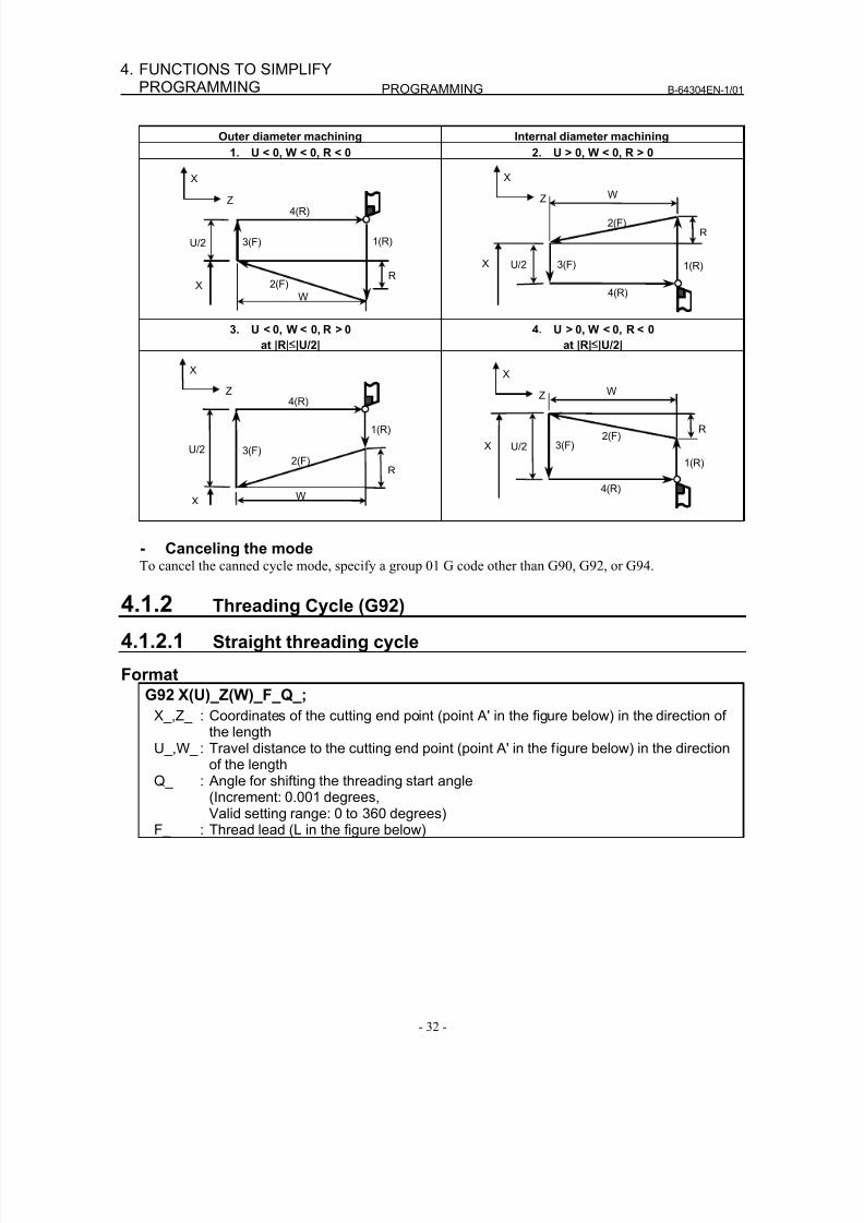
8/16/2019 Manual Operacion para FANUC
http://slidepdf.com/reader/full/manual-operacion-para-fanuc 50/435
PROGRAMMING B-64304EN-1/01
- 32 -
4. FUNCTIONS TO SIMPLIFYPROGRAMMING
Outer diameter machining Internal diameter machining
1. U < 0, W < 0, R < 0 2. U > 0, W < 0, R > 0
X
Z
U/2 3(F)
4(R)
1(R)
2(F)
W
RX
X
Z
U/2 3(F)
4(R)
1(R)
2(F)
W
R
X
3. U < 0, W < 0, R > 0
at |R|≤|U/2|
4. U > 0, W < 0, R < 0
at |R|≤|U/2|
X
Z
U/2 3(F)
4(R)
1(R)
2(F)
W
R
X
X
Z
U/2 3(F)
4(R)
1(R)
2(F)
W
R
X
- Canceling the modeTo cancel the canned cycle mode, specify a group 01 G code other than G90, G92, or G94.
4.1.2 Threading Cycle (G92)
4.1.2.1 Straight threading cycle
Format
G92 X(U)_Z(W)_F_Q_;
X_,Z_ : Coordinates of the cutting end point (point A' in the figure below) in the direction ofthe length
U_,W_ : Travel distance to the cutting end point (point A' in the figure below) in the direction
of the lengthQ_ : Angle for shifting the threading start angle(Increment: 0.001 degrees,Valid setting range: 0 to 360 degrees)
F_ : Thread lead (L in the figure below)
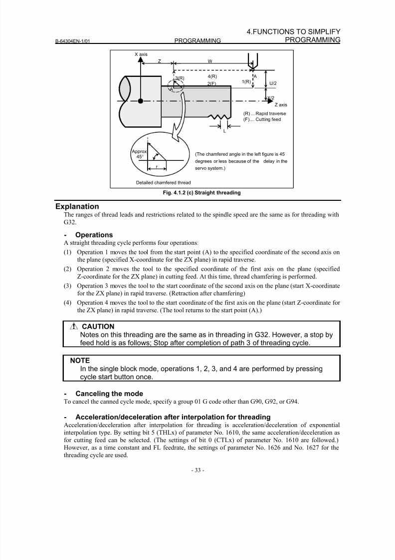
8/16/2019 Manual Operacion para FANUC
http://slidepdf.com/reader/full/manual-operacion-para-fanuc 51/435
B-64304EN-1/01 PROGRAMMING
- 33 -
4.FUNCTIONS TO SIMPLIFYPROGRAMMING
X/2
X axis
Z axis
Z
L
1(R)2(F)
3(R) 4(R)
Detailed chamfered thread
(The chamfered angle in the left figure is 45
degrees or less because of the delay in the
servo system.)
W
Approx.45°
(R) ... Rapid traverse
(F).... Cutting feed
A
A’
U/2
r
Fig. 4.1.2 (c) Straight threading
ExplanationThe ranges of thread leads and restrictions related to the spindle speed are the same as for threading with
G32.
- OperationsA straight threading cycle performs four operations:
(1) Operation 1 moves the tool from the start point (A) to the specified coordinate of the second axis on
the plane (specified X-coordinate for the ZX plane) in rapid traverse.
(2) Operation 2 moves the tool to the specified coordinate of the first axis on the plane (specified
Z-coordinate for the ZX plane) in cutting feed. At this time, thread chamfering is performed.
(3) Operation 3 moves the tool to the start coordinate of the second axis on the plane (start X-coordinate
for the ZX plane) in rapid traverse. (Retraction after chamfering)
(4) Operation 4 moves the tool to the start coordinate of the first axis on the plane (start Z-coordinate for
the ZX plane) in rapid traverse. (The tool returns to the start point (A).)
CAUTIONNotes on this threading are the same as in threading in G32. However, a stop byfeed hold is as follows; Stop after completion of path 3 of threading cycle.
NOTEIn the single block mode, operations 1, 2, 3, and 4 are performed by pressingcycle start button once.
- Canceling the modeTo cancel the canned cycle mode, specify a group 01 G code other than G90, G92, or G94.
- Acceleration/deceleration after interpolation for threadingAcceleration/deceleration after interpolation for threading is acceleration/deceleration of exponential
interpolation type. By setting bit 5 (THLx) of parameter No. 1610, the same acceleration/deceleration as
for cutting feed can be selected. (The settings of bit 0 (CTLx) of parameter No. 1610 are followed.)However, as a time constant and FL feedrate, the settings of parameter No. 1626 and No. 1627 for the
threading cycle are used.
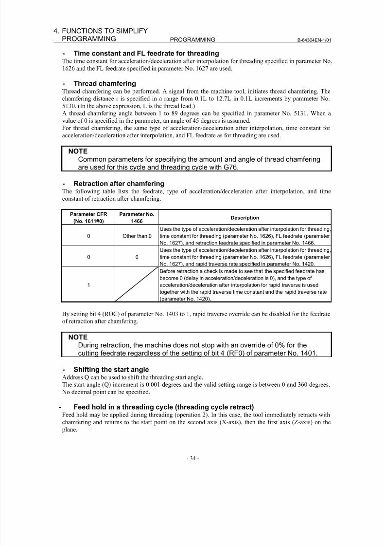
8/16/2019 Manual Operacion para FANUC
http://slidepdf.com/reader/full/manual-operacion-para-fanuc 52/435
PROGRAMMING B-64304EN-1/01
- 34 -
4. FUNCTIONS TO SIMPLIFYPROGRAMMING
- Time constant and FL feedrate for threadingThe time constant for acceleration/deceleration after interpolation for threading specified in parameter No.
1626 and the FL feedrate specified in parameter No. 1627 are used.
- Thread chamferingThread chamfering can be performed. A signal from the machine tool, initiates thread chamfering. The
chamfering distance r is specified in a range from 0.1L to 12.7L in 0.1L increments by parameter No.
5130. (In the above expression, L is the thread lead.)
A thread chamfering angle between 1 to 89 degrees can be specified in parameter No. 5131. When a
value of 0 is specified in the parameter, an angle of 45 degrees is assumed.
For thread chamfering, the same type of acceleration/deceleration after interpolation, time constant for
acceleration/deceleration after interpolation, and FL feedrate as for threading are used.
NOTECommon parameters for specifying the amount and angle of thread chamferingare used for this cycle and threading cycle with G76.
- Retraction after chamferingThe following table lists the feedrate, type of acceleration/deceleration after interpolation, and time
constant of retraction after chamfering.
Parameter CFR
(No. 1611#0)
Parameter No.
1466Description
0 Other than 0
Uses the type of acceleration/deceleration after interpolation for threading,
time constant for threading (parameter No. 1626), FL feedrate (parameter
No. 1627), and retraction feedrate specified in parameter No. 1466.
0 0
Uses the type of acceleration/deceleration after interpolation for threading,
time constant for threading (parameter No. 1626), FL feedrate (parameterNo. 1627), and rapid traverse rate specified in parameter No. 1420.
1
Before retraction a check is made to see that the specified feedrate has
become 0 (delay in acceleration/deceleration is 0), and the type of
acceleration/deceleration after interpolation for rapid traverse is used
together with the rapid traverse time constant and the rapid traverse rate
(parameter No. 1420).
By setting bit 4 (ROC) of parameter No. 1403 to 1, rapid traverse override can be disabled for the feedrate
of retraction after chamfering.
NOTE
During retraction, the machine does not stop with an override of 0% for thecutting feedrate regardless of the setting of bit 4 (RF0) of parameter No. 1401.
- Shifting the start angleAddress Q can be used to shift the threading start angle.
The start angle (Q) increment is 0.001 degrees and the valid setting range is between 0 and 360 degrees.
No decimal point can be specified.
- Feed hold in a threading cycle (threading cycle retract)Feed hold may be applied during threading (operation 2). In this case, the tool immediately retracts with
chamfering and returns to the start point on the second axis (X-axis), then the first axis (Z-axis) on the
plane.
8/16/2019 Manual Operacion para FANUC
http://slidepdf.com/reader/full/manual-operacion-para-fanuc 53/435
B-64304EN-1/01 PROGRAMMING
- 35 -
4.FUNCTIONS TO SIMPLIFYPROGRAMMING
Feed hold is effected here.
Start point
Ordinary cycle
Rapid traverse
Motion at feed hold
X axis
Z axis
Cutting feed
The chamfered angle is the same as that at the end point.
CAUTION
Another feed hold cannot be made during retreat.
- Inch threadingInch threading specified with address E is not allowed.
4.1.2.2 Taper threading cycle
Format
G92 X(U)_Z(W)_R_F_Q_;
X_,Z_ : Coordinates of the cutting end point (point A' in the figure below) in the direction ofthe length
U_,W_ : Travel distance to the cutting end point (point A' in the figure below) in the directionof the length
Q_ : Angle for shifting the threading start angle(Increment: 0.001 degrees, Valid setting range: 0 to 360 degrees)
R_ : Taper amount (R in the figure below)F_ : Thread lead (L in the figure below)
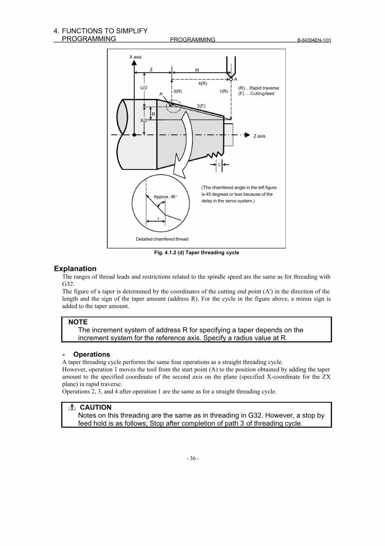
8/16/2019 Manual Operacion para FANUC
http://slidepdf.com/reader/full/manual-operacion-para-fanuc 54/435
PROGRAMMING B-64304EN-1/01
- 36 -
4. FUNCTIONS TO SIMPLIFYPROGRAMMING
Detailed chamfered thread
1(R)
Z axis
3(R)4(R)
2(F)
U/2
X/2
R
WZ
X axis
L
Approx. 45°
r
(The chamfered angle in the left figure
is 45 degrees or less because of the
delay in the servo system.)
(R)....Rapid traverse
(F) ....Cutting feed
A
A’
Fig. 4.1.2 (d) Taper threading cycle
ExplanationThe ranges of thread leads and restrictions related to the spindle speed are the same as for threading with
G32.
The figure of a taper is determined by the coordinates of the cutting end point (A') in the direction of the
length and the sign of the taper amount (address R). For the cycle in the figure above, a minus sign is
added to the taper amount.
NOTEThe increment system of address R for specifying a taper depends on theincrement system for the reference axis. Specify a radius value at R.
- OperationsA taper threading cycle performs the same four operations as a straight threading cycle.
However, operation 1 moves the tool from the start point (A) to the position obtained by adding the taper
amount to the specified coordinate of the second axis on the plane (specified X-coordinate for the ZX
plane) in rapid traverse.
Operations 2, 3, and 4 after operation 1 are the same as for a straight threading cycle.
CAUTIONNotes on this threading are the same as in threading in G32. However, a stop byfeed hold is as follows; Stop after completion of path 3 of threading cycle.
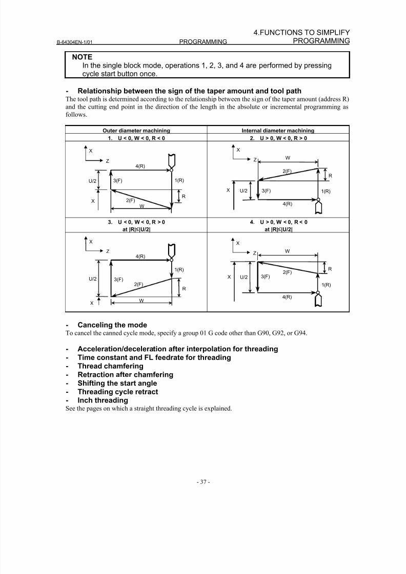
8/16/2019 Manual Operacion para FANUC
http://slidepdf.com/reader/full/manual-operacion-para-fanuc 55/435
B-64304EN-1/01 PROGRAMMING
- 37 -
4.FUNCTIONS TO SIMPLIFYPROGRAMMING
NOTEIn the single block mode, operations 1, 2, 3, and 4 are performed by pressingcycle start button once.
- Relationship between the sign of the taper amount and tool pathThe tool path is determined according to the relationship between the sign of the taper amount (address R)
and the cutting end point in the direction of the length in the absolute or incremental programming as
follows.
Outer diameter machining Internal diameter machining
1. U < 0, W < 0, R < 0 2. U > 0, W < 0, R > 0
X
Z
U/2 3(F)
4(R)
1(R)
2(F)
W
RX
X
Z
U/2 3(F)
4(R)
1(R)
2(F)
W
R
X
3. U < 0, W < 0, R > 0
at |R|≤
|U/2|
4. U > 0, W < 0, R < 0
at |R|≤
|U/2|
X
Z
U/2 3(F)
4(R)
1(R)
2(F)
W
R
X
X
Z
U/2 3(F)
4(R)
1(R)
2(F)
W
RX
- Canceling the modeTo cancel the canned cycle mode, specify a group 01 G code other than G90, G92, or G94.
- Acceleration/deceleration after interpolation for threading
- Time constant and FL feedrate for threading- Thread chamfering- Retraction after chamfering- Shifting the start angle- Threading cycle retract- Inch threadingSee the pages on which a straight threading cycle is explained.
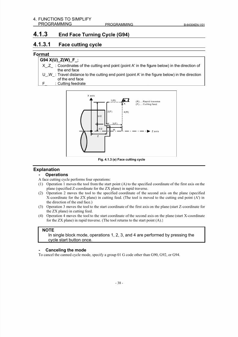
8/16/2019 Manual Operacion para FANUC
http://slidepdf.com/reader/full/manual-operacion-para-fanuc 56/435
PROGRAMMING B-64304EN-1/01
- 38 -
4. FUNCTIONS TO SIMPLIFYPROGRAMMING
4.1.3 End Face Turning Cycle (G94)
4.1.3.1 Face cutting cycle
FormatG94 X(U)_Z(W)_F_;
X_,Z_ : Coordinates of the cutting end point (point A' in the figure below) in the direction ofthe end face
U_,W_ : Travel distance to the cutting end point (point A' in the figure below) in the directionof the end face
F_ : Cutting feedrate
X axis
4(R)
X /2
3(F)
Z axis
1(R)
2(F)
Z
W
(R) .. . Rapid traverse
(F) . .. . Cutt ing feed
U/2
A
A’
Fig. 4.1.3 (e) Face cutting cycle
Explanation- OperationsA face cutting cycle performs four operations:
(1) Operation 1 moves the tool from the start point (A) to the specified coordinate of the first axis on the
plane (specified Z-coordinate for the ZX plane) in rapid traverse.
(2) Operation 2 moves the tool to the specified coordinate of the second axis on the plane (specified
X-coordinate for the ZX plane) in cutting feed. (The tool is moved to the cutting end point (A') in
the direction of the end face.)
(3) Operation 3 moves the tool to the start coordinate of the first axis on the plane (start Z-coordinate for
the ZX plane) in cutting feed.(4) Operation 4 moves the tool to the start coordinate of the second axis on the plane (start X-coordinate
for the ZX plane) in rapid traverse. (The tool returns to the start point (A).)
NOTEIn single block mode, operations 1, 2, 3, and 4 are performed by pressing thecycle start button once.
- Canceling the modeTo cancel the canned cycle mode, specify a group 01 G code other than G90, G92, or G94.
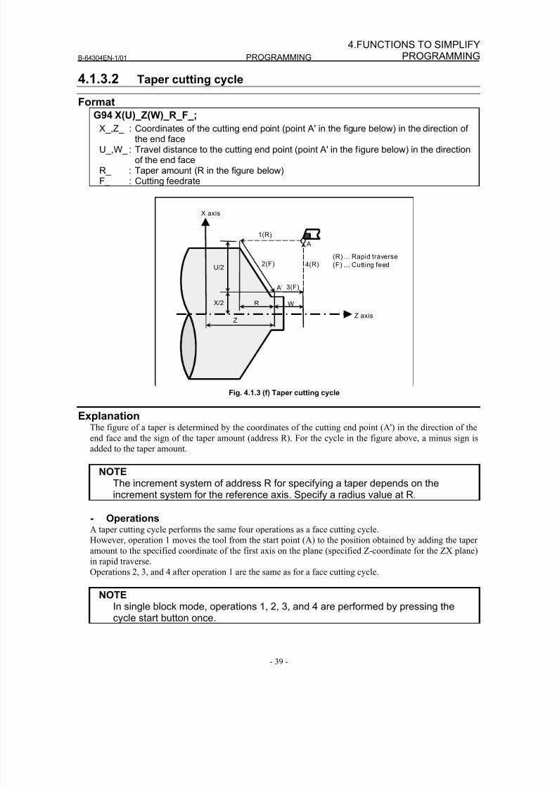
8/16/2019 Manual Operacion para FANUC
http://slidepdf.com/reader/full/manual-operacion-para-fanuc 57/435
B-64304EN-1/01 PROGRAMMING
- 39 -
4.FUNCTIONS TO SIMPLIFYPROGRAMMING
4.1.3.2 Taper cutting cycle
Format
G94 X(U)_Z(W)_R_F_;
X_,Z_ : Coordinates of the cutting end point (point A' in the figure below) in the direction ofthe end face
U_,W_ : Travel distance to the cutting end point (point A' in the figure below) in the directionof the end face
R_ : Taper amount (R in the figure below)F_ : Cutting feedrate
(R) ... Rapid traverse
(F) ... Cutting feed4(R)
X/2
3(F)
Z axis
1(R)
2(F)U/2
Z
WR
X axis
A
A’
Fig. 4.1.3 (f) Taper cutting cycle
ExplanationThe figure of a taper is determined by the coordinates of the cutting end point (A') in the direction of the
end face and the sign of the taper amount (address R). For the cycle in the figure above, a minus sign is
added to the taper amount.
NOTEThe increment system of address R for specifying a taper depends on the
increment system for the reference axis. Specify a radius value at R.
- OperationsA taper cutting cycle performs the same four operations as a face cutting cycle.
However, operation 1 moves the tool from the start point (A) to the position obtained by adding the taper
amount to the specified coordinate of the first axis on the plane (specified Z-coordinate for the ZX plane)
in rapid traverse.
Operations 2, 3, and 4 after operation 1 are the same as for a face cutting cycle.
NOTEIn single block mode, operations 1, 2, 3, and 4 are performed by pressing the
cycle start button once.
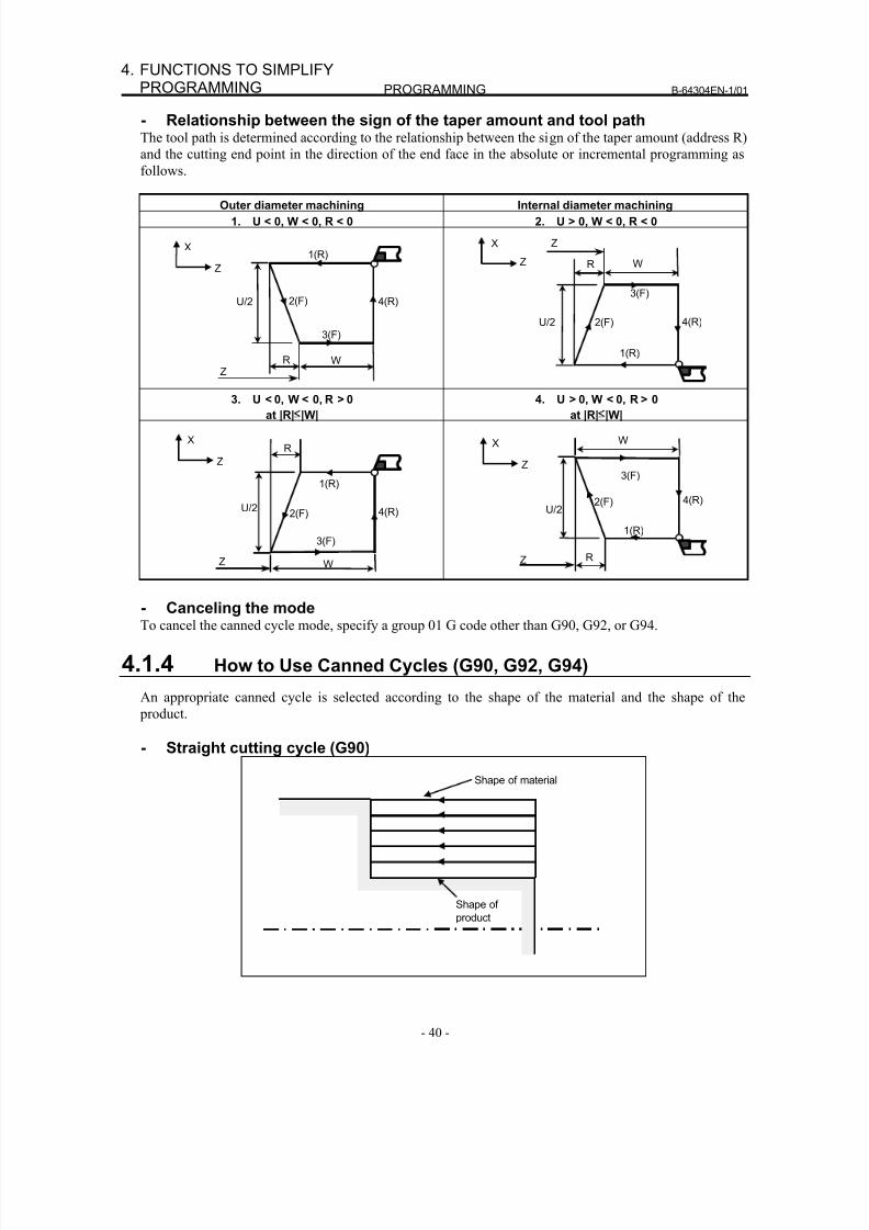
8/16/2019 Manual Operacion para FANUC
http://slidepdf.com/reader/full/manual-operacion-para-fanuc 58/435
PROGRAMMING B-64304EN-1/01
- 40 -
4. FUNCTIONS TO SIMPLIFYPROGRAMMING
- Relationship between the sign of the taper amount and tool pathThe tool path is determined according to the relationship between the sign of the taper amount (address R)
and the cutting end point in the direction of the end face in the absolute or incremental programming as
follows.
Outer diameter machining Internal diameter machining
1. U < 0, W < 0, R < 0 2. U > 0, W < 0, R < 0
X1(R)
Z
U/2
3(F)
4(R)2(F)
WRZ
Z
U/2
3(F)
4(R)2(F)
WR
X
1(R)
Z
3. U < 0, W < 0, R > 0
at |R|≤|W|
4. U > 0, W < 0, R > 0
at |R|≤|W|
W
Z
U/2
3(F)
4(R)2(F)
RX
1(R)
Z
Z
X W
U/2
3(F)
4(R)2(F)
R
1(R)
Z
- Canceling the modeTo cancel the canned cycle mode, specify a group 01 G code other than G90, G92, or G94.
4.1.4 How to Use Canned Cycles (G90, G92, G94)
An appropriate canned cycle is selected according to the shape of the material and the shape of the
product.
- Straight cutting cycle (G90)
Shape of
product
Shape of material
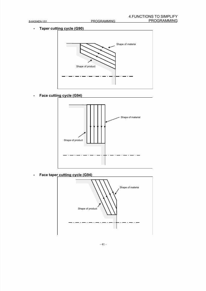
8/16/2019 Manual Operacion para FANUC
http://slidepdf.com/reader/full/manual-operacion-para-fanuc 59/435
B-64304EN-1/01 PROGRAMMING
- 41 -
4.FUNCTIONS TO SIMPLIFYPROGRAMMING
- Taper cutting cycle (G90)
Shape of product
Shape of material
- Face cutting cycle (G94)
Shape of product
Shape of material
- Face taper cutting cycle (G94)
Shape of product
Shape of material
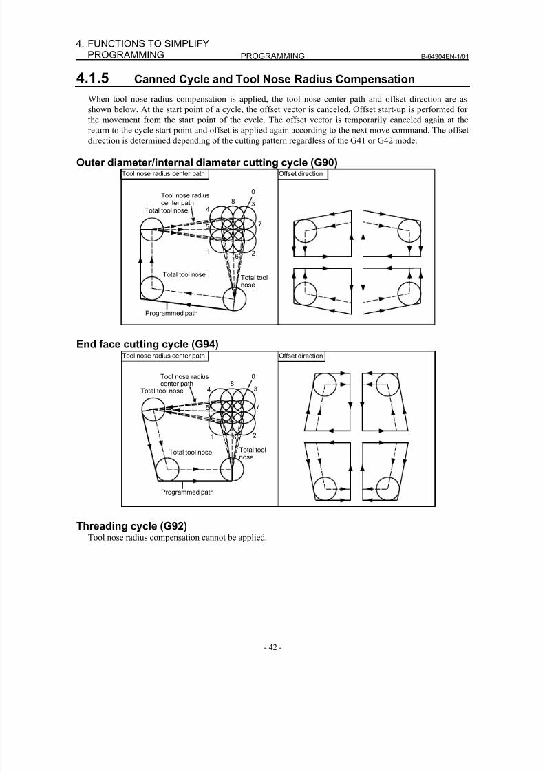
8/16/2019 Manual Operacion para FANUC
http://slidepdf.com/reader/full/manual-operacion-para-fanuc 60/435
PROGRAMMING B-64304EN-1/01
- 42 -
4. FUNCTIONS TO SIMPLIFYPROGRAMMING
4.1.5 Canned Cycle and Tool Nose Radius Compensation
When tool nose radius compensation is applied, the tool nose center path and offset direction are as
shown below. At the start point of a cycle, the offset vector is canceled. Offset start-up is performed for
the movement from the start point of the cycle. The offset vector is temporarily canceled again at thereturn to the cycle start point and offset is applied again according to the next move command. The offset
direction is determined depending of the cutting pattern regardless of the G41 or G42 mode.
Outer diameter/internal diameter cutting cycle (G90)Tool nose radius center path Offset direction
Total tool nose
Tool nose radiuscenter path
Programmed path
0
8
4
5 7
3
16 2
Total toolnose
Total tool nose
End face cutting cycle (G94)
Total tool nose
Tool nose radiuscenter path
Programmed path
08
4
5 7
3
1 6 2
Total toolnose
Total tool nose
Tool nose radius center path Offset direction
Threading cycle (G92)Tool nose radius compensation cannot be applied.
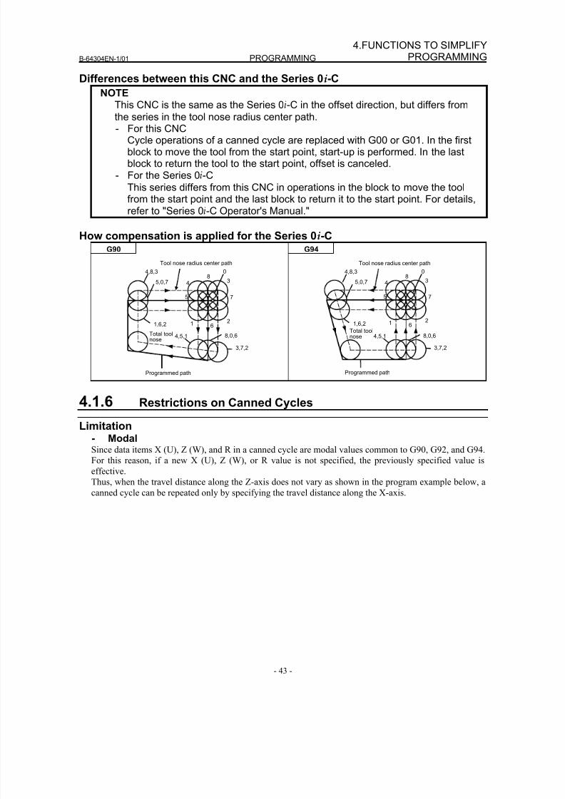
8/16/2019 Manual Operacion para FANUC
http://slidepdf.com/reader/full/manual-operacion-para-fanuc 61/435
B-64304EN-1/01 PROGRAMMING
- 43 -
4.FUNCTIONS TO SIMPLIFYPROGRAMMING
Differences between this CNC and the Series 0i-C
NOTEThis CNC is the same as the Series 0i-C in the offset direction, but differs from
the series in the tool nose radius center path.
- For this CNCCycle operations of a canned cycle are replaced with G00 or G01. In the firstblock to move the tool from the start point, start-up is performed. In the lastblock to return the tool to the start point, offset is canceled.
- For the Series 0i-C
This series differs from this CNC in operations in the block to move the toolfrom the start point and the last block to return it to the start point. For details,refer to "Series 0i-C Operator's Manual."
How compensation is applied for the Series 0i-C
G90 G94
4,8,3
5,0,7
1,6,2
4,5,1
8,0,6
3,7,2
Total toolnose
Tool nose radius center path
Programmed path
0
8
4
5 7
3
1 6
2
0
8
4
5 7
3
1 6
2
4,5,1 8,0,6
3,7,2
Total toolnose
4,8,3
5,0,7
1,6,2
Programmed path
Tool nose radius center path
4.1.6 Restrictions on Canned Cycles
Limitation- ModalSince data items X (U), Z (W), and R in a canned cycle are modal values common to G90, G92, and G94.
For this reason, if a new X (U), Z (W), or R value is not specified, the previously specified value is
effective.
Thus, when the travel distance along the Z-axis does not vary as shown in the program example below, a
canned cycle can be repeated only by specifying the travel distance along the X-axis.
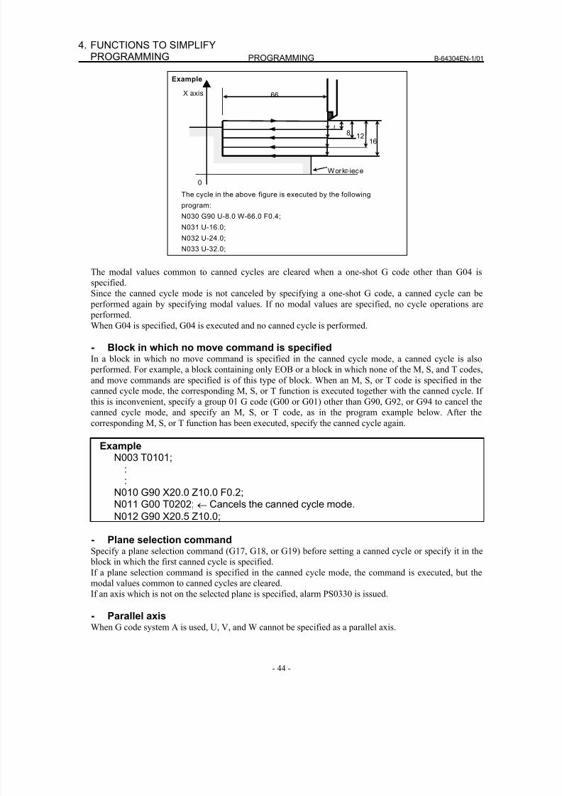
8/16/2019 Manual Operacion para FANUC
http://slidepdf.com/reader/full/manual-operacion-para-fanuc 62/435
PROGRAMMING B-64304EN-1/01
- 44 -
4. FUNCTIONS TO SIMPLIFYPROGRAMMING
Example
Work iece
16128
66 X axis
0
The cycle in the above figure is executed by the following
program:
N030 G90 U-8.0 W-66.0 F0.4;
N031 U-16.0;
N032 U-24.0;
N033 U-32.0;
The modal values common to canned cycles are cleared when a one-shot G code other than G04 is
specified.
Since the canned cycle mode is not canceled by specifying a one-shot G code, a canned cycle can be
performed again by specifying modal values. If no modal values are specified, no cycle operations are
performed.
When G04 is specified, G04 is executed and no canned cycle is performed.
- Block in which no move command is specifiedIn a block in which no move command is specified in the canned cycle mode, a canned cycle is also
performed. For example, a block containing only EOB or a block in which none of the M, S, and T codes,
and move commands are specified is of this type of block. When an M, S, or T code is specified in the
canned cycle mode, the corresponding M, S, or T function is executed together with the canned cycle. If
this is inconvenient, specify a group 01 G code (G00 or G01) other than G90, G92, or G94 to cancel the
canned cycle mode, and specify an M, S, or T code, as in the program example below. After the
corresponding M, S, or T function has been executed, specify the canned cycle again.
ExampleN003 T0101;
::
N010 G90 X20.0 Z10.0 F0.2;N011 G00 T0202; ← Cancels the canned cycle mode.
N012 G90 X20.5 Z10.0;
- Plane selection commandSpecify a plane selection command (G17, G18, or G19) before setting a canned cycle or specify it in the
block in which the first canned cycle is specified.
If a plane selection command is specified in the canned cycle mode, the command is executed, but the
modal values common to canned cycles are cleared.
If an axis which is not on the selected plane is specified, alarm PS0330 is issued.
- Parallel axis
When G code system A is used, U, V, and W cannot be specified as a parallel axis.
8/16/2019 Manual Operacion para FANUC
http://slidepdf.com/reader/full/manual-operacion-para-fanuc 63/435
B-64304EN-1/01 PROGRAMMING
- 45 -
4.FUNCTIONS TO SIMPLIFYPROGRAMMING
- ResetIf a reset operation is performed during execution of a canned cycle when any of the following states for
holding a modal G code of group 01 is set, the modal G code of group 01 is replaced with the G01 mode:
• Reset state (bit 6 (CLR) of parameter No. 3402 = 0)
• Cleared state (bit 6 (CLR) of parameter No. 3402 = 1) and state where the modal G code of group 01is held at reset time (bit 1 (C01) of parameter No. 3406 = 1)
Example of operation)
If a reset is made during execution of a canned cycle (X0 block) and the X20.Z1. command is
executed, linear interpolation (G01) is performed instead of the canned cycle.
4.2 MULTIPLE REPETITIVE CANNED CYCLE (G70-G76)
The multiple repetitive canned cycle is canned cycles to make CNC programming easy. For instance, the
data of the finish work shape describes the tool path for rough machining. And also, a canned cycles for
the threading is available.
NOTE1 Explanatory figures in this section use the ZX plane as the selected plane,
diameter programming for the X-axis, and radius programming for the Z-axis.When radius programming is used for the X-axis, change U/2 to U and X/2 to X.
2 A multiple repetitive canned cycle can be performed on any plane (includingparallel axes for plane definition). When G-code system A is used, however, U,V, and W cannot be set as a parallel axis.
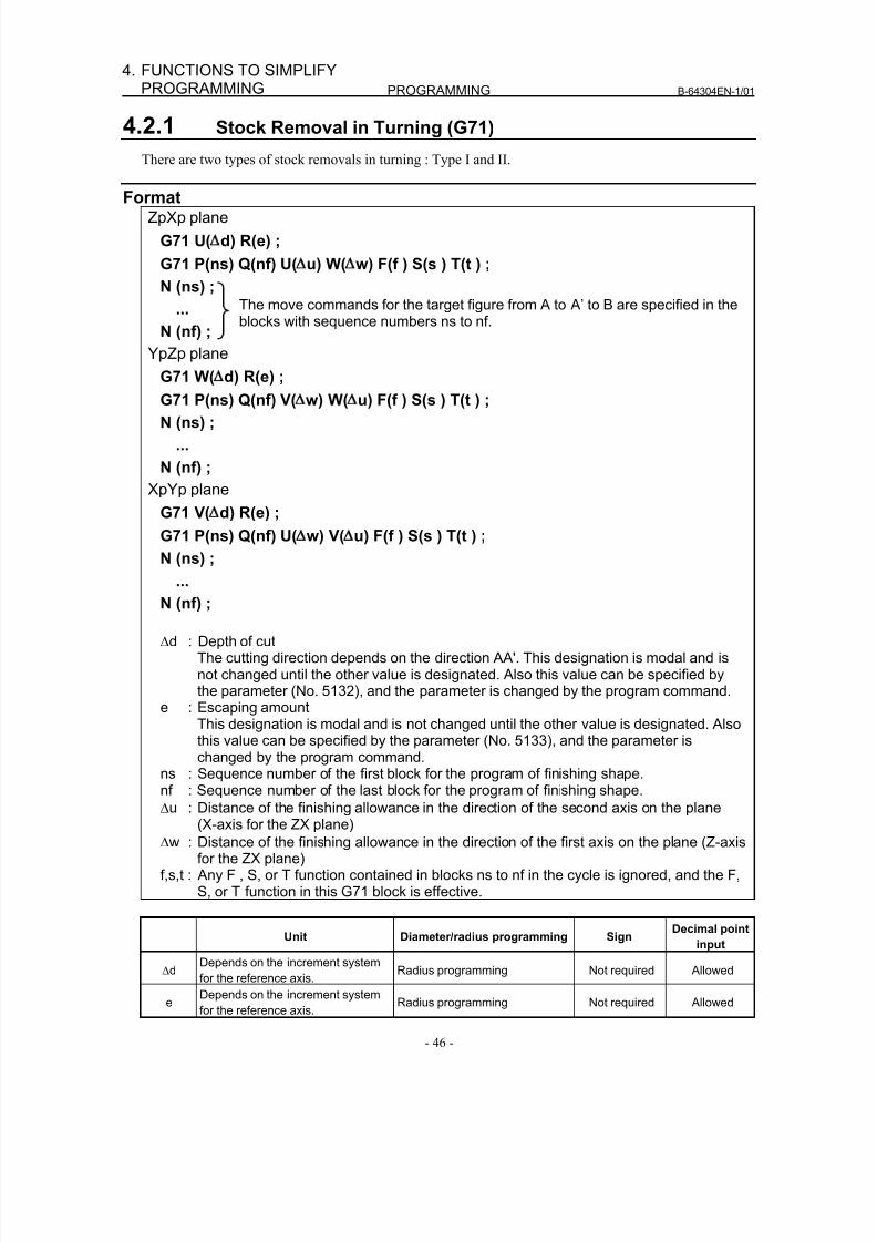
8/16/2019 Manual Operacion para FANUC
http://slidepdf.com/reader/full/manual-operacion-para-fanuc 64/435
PROGRAMMING B-64304EN-1/01
- 46 -
4. FUNCTIONS TO SIMPLIFYPROGRAMMING
4.2.1 Stock Removal in Turning (G71)
There are two types of stock removals in turning : Type I and II.
FormatZpXp plane
G71 U( d) R(e) ;
G71 P(ns) Q(nf) U( u) W( w) F(f ) S(s ) T(t ) ;
N (ns) ;
...
N (nf) ;
YpZp plane
G71 W( d) R(e) ;
G71 P(ns) Q(nf) V( w) W( u) F(f ) S(s ) T(t ) ;
N (ns) ;
...
N (nf) ;
XpYp plane
G71 V( d) R(e) ;
G71 P(ns) Q(nf) U( w) V( u) F(f ) S(s ) T(t ) ;
N (ns) ;
...N (nf) ;
Δd : Depth of cutThe cutting direction depends on the direction AA'. This designation is modal and isnot changed until the other value is designated. Also this value can be specified bythe parameter (No. 5132), and the parameter is changed by the program command.
e : Escaping amountThis designation is modal and is not changed until the other value is designated. Alsothis value can be specified by the parameter (No. 5133), and the parameter ischanged by the program command.
ns : Sequence number of the first block for the program of finishing shape.nf : Sequence number of the last block for the program of finishing shape.
Δu : Distance of the finishing allowance in the direction of the second axis on the plane(X-axis for the ZX plane)
Δw : Distance of the finishing allowance in the direction of the first axis on the plane (Z-axisfor the ZX plane)
f,s,t : Any F , S, or T function contained in blocks ns to nf in the cycle is ignored, and the F,S, or T function in this G71 block is effective.
Unit Diameter/radius programming SignDecimal point
input
Δd
Depends on the increment system
for the reference axis. Radius programming Not required Allowed
eDepends on the increment system
for the reference axis.Radius programming Not required Allowed
The move commands for the target figure from A to A’ to B are specified in theblocks with sequence numbers ns to nf.
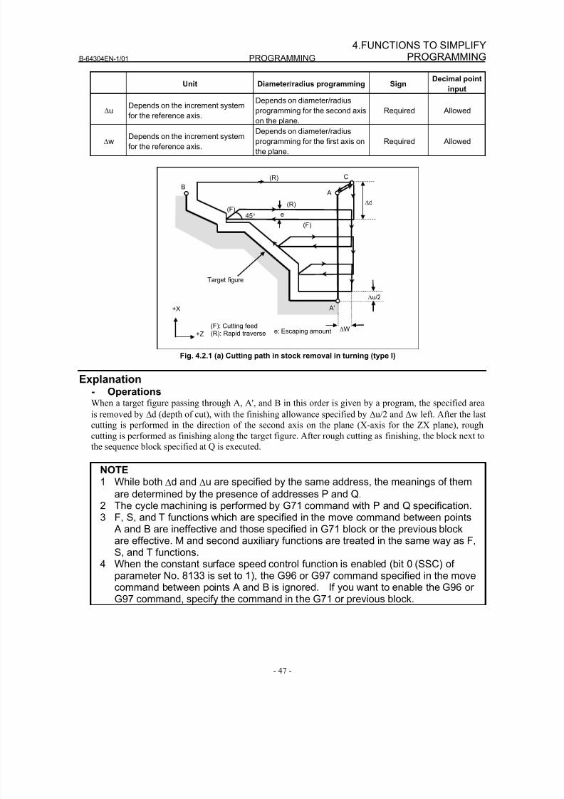
8/16/2019 Manual Operacion para FANUC
http://slidepdf.com/reader/full/manual-operacion-para-fanuc 65/435
B-64304EN-1/01 PROGRAMMING
- 47 -
4.FUNCTIONS TO SIMPLIFYPROGRAMMING
Unit Diameter/radius programming SignDecimal point
input
ΔuDepends on the increment system
for the reference axis.
Depends on diameter/radius
programming for the second axis
on the plane.
Required Allowed
ΔwDepends on the increment system
for the reference axis.
Depends on diameter/radius
programming for the first axis on
the plane.
Required Allowed
C
B
(R)
(R)
(F)
(F)
A
Δu/2
Δd
A’
ΔW
Target figure
45° e
(F): Cutting feed(R): Rapid traverse
+X
+Z e: Escaping amount
Fig. 4.2.1 (a) Cutting path in stock removal in turning (type I)
Explanation- OperationsWhen a target figure passing through A, A', and B in this order is given by a program, the specified area
is removed by Δd (depth of cut), with the finishing allowance specified by Δu/2 and Δw left. After the last
cutting is performed in the direction of the second axis on the plane (X-axis for the ZX plane), rough
cutting is performed as finishing along the target figure. After rough cutting as finishing, the block next to
the sequence block specified at Q is executed.
NOTE1 While both Δd and Δu are specified by the same address, the meanings of them
are determined by the presence of addresses P and Q.
2 The cycle machining is performed by G71 command with P and Q specification.3 F, S, and T functions which are specified in the move command between points
A and B are ineffective and those specified in G71 block or the previous blockare effective. M and second auxiliary functions are treated in the same way as F,S, and T functions.
4 When the constant surface speed control function is enabled (bit 0 (SSC) ofparameter No. 8133 is set to 1), the G96 or G97 command specified in the movecommand between points A and B is ignored. If you want to enable the G96 orG97 command, specify the command in the G71 or previous block.
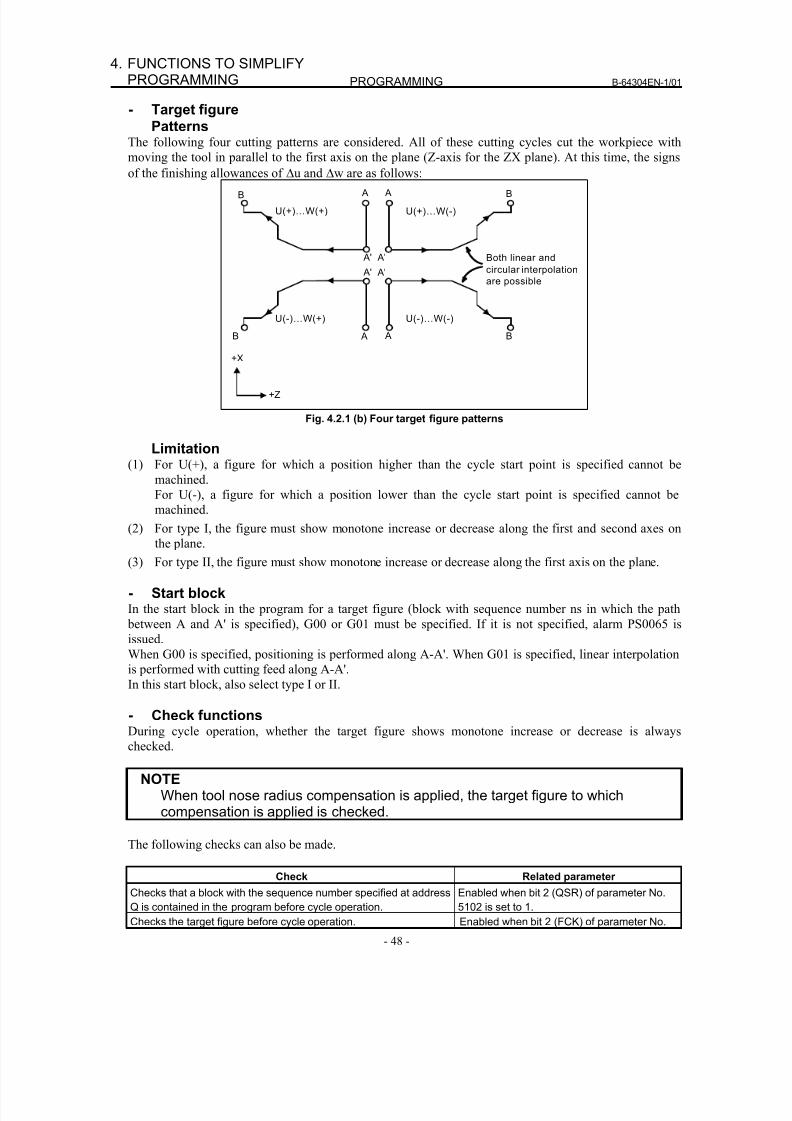
8/16/2019 Manual Operacion para FANUC
http://slidepdf.com/reader/full/manual-operacion-para-fanuc 66/435
PROGRAMMING B-64304EN-1/01
- 48 -
4. FUNCTIONS TO SIMPLIFYPROGRAMMING
- Target figurePatterns
The following four cutting patterns are considered. All of these cutting cycles cut the workpiece with
moving the tool in parallel to the first axis on the plane (Z-axis for the ZX plane). At this time, the signs
of the finishing allowances of Δu and Δw are as follows:
Both linear and
circular interpolation
are possible
A'
B
U(+)…W(+)
A'
B A
U(+)…W(-)
A'
B A
U(-)…W(+)
A'
B A
U(-)…W(-)
A
+X
+Z
Fig. 4.2.1 (b) Four target figure patterns
Limitation(1) For U(+), a figure for which a position higher than the cycle start point is specified cannot be
machined.
For U(-), a figure for which a position lower than the cycle start point is specified cannot be
machined.
(2) For type I, the figure must show monotone increase or decrease along the first and second axes onthe plane.
(3) For type II, the figure must show monotone increase or decrease along the first axis on the plane.
- Start blockIn the start block in the program for a target figure (block with sequence number ns in which the path
between A and A' is specified), G00 or G01 must be specified. If it is not specified, alarm PS0065 is
issued.
When G00 is specified, positioning is performed along A-A'. When G01 is specified, linear interpolation
is performed with cutting feed along A-A'.
In this start block, also select type I or II.
- Check functionsDuring cycle operation, whether the target figure shows monotone increase or decrease is always
checked.
NOTEWhen tool nose radius compensation is applied, the target figure to whichcompensation is applied is checked.
The following checks can also be made.
Check Related parameterChecks that a block with the sequence number specified at address
Q is contained in the program before cycle operation.
Enabled when bit 2 (QSR) of parameter No.
5102 is set to 1.
Checks the target figure before cycle operation. Enabled when bit 2 (FCK) of parameter No.
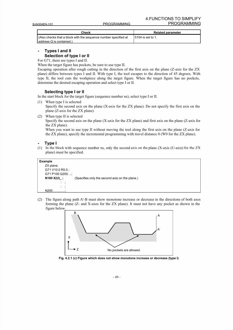
8/16/2019 Manual Operacion para FANUC
http://slidepdf.com/reader/full/manual-operacion-para-fanuc 67/435
B-64304EN-1/01 PROGRAMMING
- 49 -
4.FUNCTIONS TO SIMPLIFYPROGRAMMING
Check Related parameter
(Also checks that a block with the sequence number specified at
address Q is contained.)
5104 is set to 1.
- Types I and IISelection of type I or II
For G71, there are types I and II.
When the target figure has pockets, be sure to use type II.
Escaping operation after rough cutting in the direction of the first axis on the plane (Z-axis for the ZX
plane) differs between types I and II. With type I, the tool escapes to the direction of 45 degrees. With
type II, the tool cuts the workpiece along the target figure. When the target figure has no pockets,
determine the desired escaping operation and select type I or II.
Selecting type I or IIIn the start block for the target figure (sequence number ns), select type I or II.
(1) When type I is selectedSpecify the second axis on the plane (X-axis for the ZX plane). Do not specify the first axis on the
plane (Z-axis for the ZX plane).
(2) When type II is selected
Specify the second axis on the plane (X-axis for the ZX plane) and first axis on the plane (Z-axis for
the ZX plane).
When you want to use type II without moving the tool along the first axis on the plane (Z-axis for
the ZX plane), specify the incremental programming with travel distance 0 (W0 for the ZX plane).
- Type I(1) In the block with sequence number ns, only the second axis on the plane (X-axis (U-axis) for the ZX
plane) must be specified.
Example
ZX plane
G71 V10.0 R5.0 ;
G71 P100 Q200....;
N100 X(U)_ ; (Specifies only the second axis on the plane.)
: ;
: ;
N200…………;
(2) The figure along path A'-B must show monotone increase or decrease in the directions of both axes
forming the plane (Z- and X-axes for the ZX plane). It must not have any pocket as shown in the
figure below.
No pockets are allowed.
A
A’
X
Z
B
Fig. 4.2.1 (c) Figure which does not show monotone increase or decrease (type I)
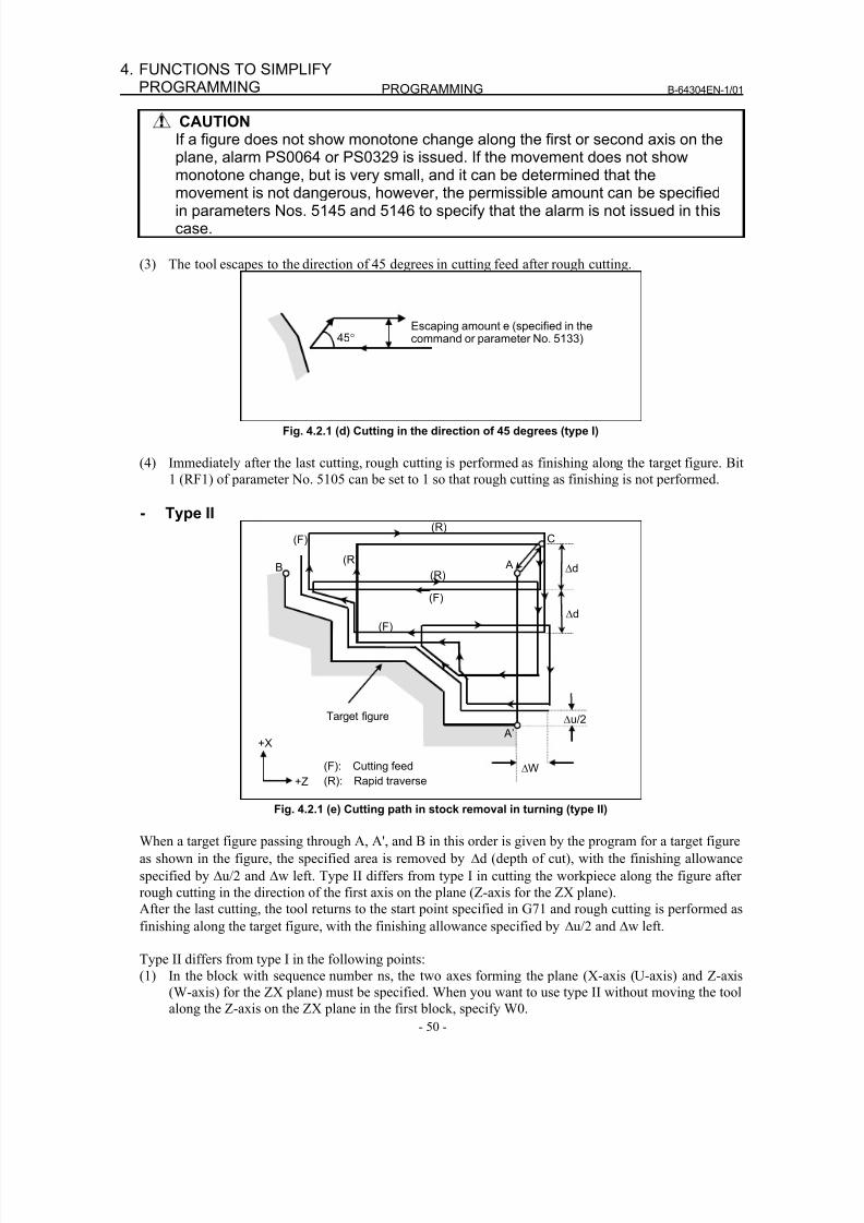
8/16/2019 Manual Operacion para FANUC
http://slidepdf.com/reader/full/manual-operacion-para-fanuc 68/435
PROGRAMMING B-64304EN-1/01
- 50 -
4. FUNCTIONS TO SIMPLIFYPROGRAMMING
CAUTIONIf a figure does not show monotone change along the first or second axis on theplane, alarm PS0064 or PS0329 is issued. If the movement does not showmonotone change, but is very small, and it can be determined that the
movement is not dangerous, however, the permissible amount can be specifiedin parameters Nos. 5145 and 5146 to specify that the alarm is not issued in thiscase.
(3) The tool escapes to the direction of 45 degrees in cutting feed after rough cutting.
Escaping amount e (specified in thecommand or parameter No. 5133)45°
Fig. 4.2.1 (d) Cutting in the direction of 45 degrees (type I)
(4) Immediately after the last cutting, rough cutting is performed as finishing along the target figure. Bit
1 (RF1) of parameter No. 5105 can be set to 1 so that rough cutting as finishing is not performed.
- Type II
C
B
(F)
A
Δu/2
Δd
A’
ΔW
Target figure
(F): Cutting feed(R): Rapid traverse
+X
+Z
(R)
Δd
(F)
(F)
(R)
(R)
Fig. 4.2.1 (e) Cutting path in stock removal in turning (type II)
When a target figure passing through A, A', and B in this order is given by the program for a target figure
as shown in the figure, the specified area is removed by Δd (depth of cut), with the finishing allowance
specified by Δu/2 and Δw left. Type II differs from type I in cutting the workpiece along the figure after
rough cutting in the direction of the first axis on the plane (Z-axis for the ZX plane).
After the last cutting, the tool returns to the start point specified in G71 and rough cutting is performed as
finishing along the target figure, with the finishing allowance specified by Δu/2 and Δw left.
Type II differs from type I in the following points:(1) In the block with sequence number ns, the two axes forming the plane (X-axis (U-axis) and Z-axis
(W-axis) for the ZX plane) must be specified. When you want to use type II without moving the tool
along the Z-axis on the ZX plane in the first block, specify W0.
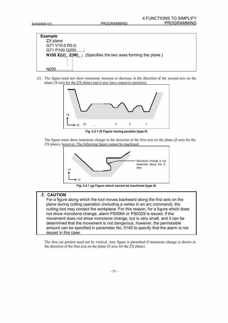
8/16/2019 Manual Operacion para FANUC
http://slidepdf.com/reader/full/manual-operacion-para-fanuc 69/435
B-64304EN-1/01 PROGRAMMING
- 51 -
4.FUNCTIONS TO SIMPLIFYPROGRAMMING
ExampleZX planeG71 V10.0 R5.0;
G71 P100 Q200.......;N100 X(U)_ Z(W)_ ; (Specifies the two axes forming the plane.)
: ;: ;
N200…………;
(2) The figure need not show monotone increase or decrease in the direction of the second axis on the
plane (X-axis for the ZX plane) and it may have concaves (pockets).
12310 . . .
+X
+Z
Fig. 4.2.1 (f) Figure having pockets (type II)
The figure must show monotone change in the direction of the first axis on the plane (Z-axis for the
ZX plane), however. The following figure cannot be machined.
Monotone change is not
observed along the Z-
axis.+X
+Z
Fig. 4.2.1 (g) Figure which cannot be machined (type II)
CAUTIONFor a figure along which the tool moves backward along the first axis on the
plane during cutting operation (including a vertex in an arc command), thecutting tool may contact the workpiece. For this reason, for a figure which doesnot show monotone change, alarm PS0064 or PS0329 is issued. If themovement does not show monotone change, but is very small, and it can bedetermined that the movement is not dangerous, however, the permissibleamount can be specified in parameter No. 5145 to specify that the alarm is notissued in this case.
The first cut portion need not be vertical. Any figure is permitted if monotone change is shown in
the direction of the first axis on the plane (Z-axis for the ZX plane).
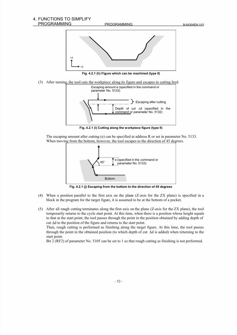
8/16/2019 Manual Operacion para FANUC
http://slidepdf.com/reader/full/manual-operacion-para-fanuc 70/435
PROGRAMMING B-64304EN-1/01
- 52 -
4. FUNCTIONS TO SIMPLIFYPROGRAMMING
+X
+Z
Fig. 4.2.1 (h) Figure which can be machined (type II)
(3) After turning, the tool cuts the workpiece along its figure and escapes in cutting feed.
Escaping amount e (specified in the command or parameter No. 5133)
Depth of cut Δd (specified in thecommand or parameter No. 5132)
Escaping after cutting
Fig. 4.2.1 (i) Cutting along the workpiece figure (type II)
The escaping amount after cutting (e) can be specified at address R or set in parameter No. 5133.
When moving from the bottom, however, the tool escapes to the direction of 45 degrees.
e (specified in the command or parameter No. 5133)45°
Bottom
Fig. 4.2.1 (j) Escaping from the bottom to the direction of 45 degrees
(4) When a position parallel to the first axis on the plane (Z-axis for the ZX plane) is specified in a
block in the program for the target figure, it is assumed to be at the bottom of a pocket.
(5) After all rough cutting terminates along the first axis on the plane (Z-axis for the ZX plane), the tooltemporarily returns to the cycle start point. At this time, when there is a position whose height equals
to that at the start point, the tool passes through the point in the position obtained by adding depth of
cut Δd to the position of the figure and returns to the start point.
Then, rough cutting is performed as finishing along the target figure. At this time, the tool passes
through the point in the obtained position (to which depth of cut Δd is added) when returning to the
start point.
Bit 2 (RF2) of parameter No. 5105 can be set to 1 so that rough cutting as finishing is not performed.
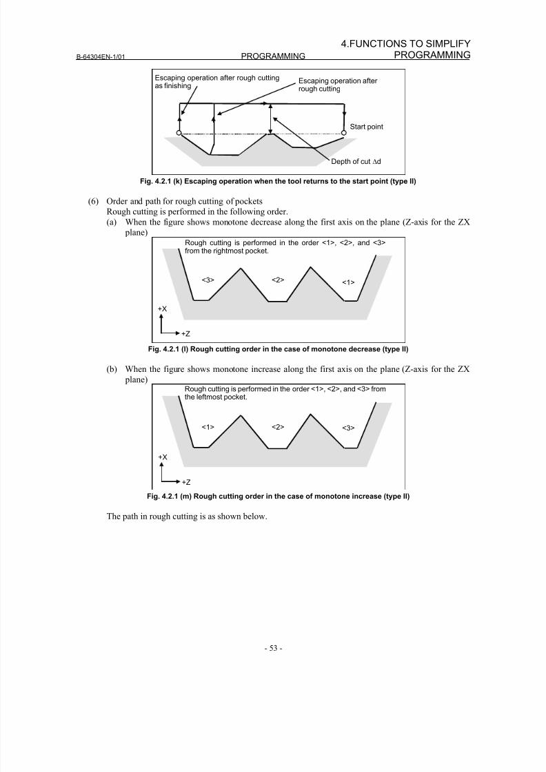
8/16/2019 Manual Operacion para FANUC
http://slidepdf.com/reader/full/manual-operacion-para-fanuc 71/435
B-64304EN-1/01 PROGRAMMING
- 53 -
4.FUNCTIONS TO SIMPLIFYPROGRAMMING
Depth of cut Δd
Start point
Escaping operation after rough cutting
Escaping operation after rough cuttingas finishing
Fig. 4.2.1 (k) Escaping operation when the tool returns to the start point (type II)
(6) Order and path for rough cutting of pockets
Rough cutting is performed in the following order.
(a) When the figure shows monotone decrease along the first axis on the plane (Z-axis for the ZX
plane)
<1><2><3>
Rough cutting is performed in the order <1>, <2>, and <3>from the rightmost pocket.
+X
+Z
Fig. 4.2.1 (l) Rough cutting order in the case of monotone decrease (type II)
(b) When the figure shows monotone increase along the first axis on the plane (Z-axis for the ZX
plane)
<3><2><1>
Rough cutting is performed in the order <1>, <2>, and <3> fromthe leftmost pocket.
+X
+Z Fig. 4.2.1 (m) Rough cutting order in the case of monotone increase (type II)
The path in rough cutting is as shown below.
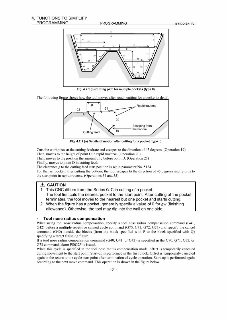
8/16/2019 Manual Operacion para FANUC
http://slidepdf.com/reader/full/manual-operacion-para-fanuc 72/435
PROGRAMMING B-64304EN-1/01
- 54 -
4. FUNCTIONS TO SIMPLIFYPROGRAMMING
18
23
28 30
27
26
24
25
22
9 102
14 20
7
13
19
5 1
611
1216
17
8
4
21
15
29
3
31
32
33
34
35
Fig. 4.2.1 (n) Cutting path for multiple pockets (type II)
The following figure shows how the tool moves after rough cutting for a pocket in detail.
19
20
22 21•
g Rapid traverse
Escaping fromthe bottom
Cutting feed
D
Fig. 4.2.1 (o) Details of motion after cutting for a pocket (type II)
Cuts the workpiece at the cutting feedrate and escapes to the direction of 45 degrees. (Operation 19)Then, moves to the height of point D in rapid traverse. (Operation 20)
Then, moves to the position the amount of g before point D. (Operation 21)
Finally, moves to point D in cutting feed.
The clearance g to the cutting feed start position is set in parameter No. 5134.
For the last pocket, after cutting the bottom, the tool escapes to the direction of 45 degrees and returns to
the start point in rapid traverse. (Operations 34 and 35)
CAUTION1 This CNC differs from the Series 0i-C in cutting of a pocket.
The tool first cuts the nearest pocket to the start point. After cutting of the pocketterminates, the tool moves to the nearest but one pocket and starts cutting.
2 When the figure has a pocket, generally specify a value of 0 for Δw (finishing
allowance). Otherwise, the tool may dig into the wall on one side.
- Tool nose radius compensationWhen using tool nose radius compensation, specify a tool nose radius compensation command (G41,
G42) before a multiple repetitive canned cycle command (G70, G71, G72, G73) and specify the cancel
command (G40) outside the blocks (from the block specified with P to the block specified with Q)
specifying a target finishing figure.
If a tool nose radius compensation command (G40, G41, or G42) is specified in the G70, G71, G72, or
G73 command, alarm PS0325 is issued.
When this cycle is specified in the tool nose radius compensation mode, offset is temporarily canceled
during movement to the start point. Start-up is performed in the first block. Offset is temporarily canceledagain at the return to the cycle start point after termination of cycle operation. Start-up is performed again
according to the next move command. This operation is shown in the figure below.
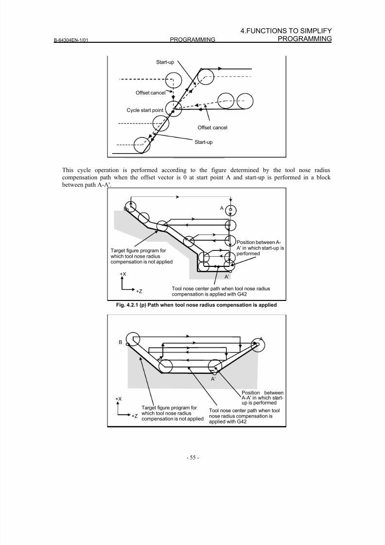
8/16/2019 Manual Operacion para FANUC
http://slidepdf.com/reader/full/manual-operacion-para-fanuc 73/435
B-64304EN-1/01 PROGRAMMING
- 55 -
4.FUNCTIONS TO SIMPLIFYPROGRAMMING
Cycle start point
Start-up
Offset cancel
Start-up
Offset cancel
This cycle operation is performed according to the figure determined by the tool nose radiuscompensation path when the offset vector is 0 at start point A and start-up is performed in a block
between path A-A'.
Target figure program for
which tool nose radiuscompensation is not applied
+X
+Z
B A
A’
Tool nose center path when tool nose radiuscompensation is applied with G42
Position between A- A' in which start-up isperformed
Fig. 4.2.1 (p) Path when tool nose radius compensation is applied
Target figure program for which tool nose radiuscompensation is not applied
+X
+ZTool nose center path when toolnose radius compensation isapplied with G42
B A
A’
Position between A-A' in which start-up is performed
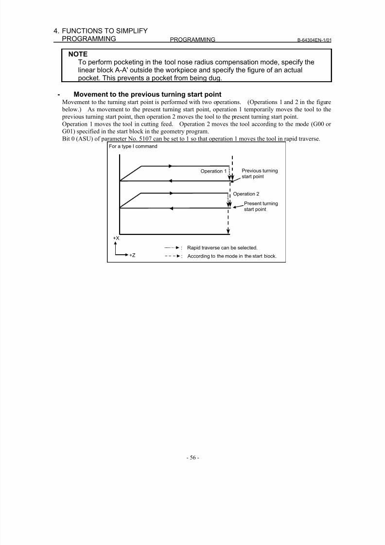
8/16/2019 Manual Operacion para FANUC
http://slidepdf.com/reader/full/manual-operacion-para-fanuc 74/435
PROGRAMMING B-64304EN-1/01
- 56 -
4. FUNCTIONS TO SIMPLIFYPROGRAMMING
NOTETo perform pocketing in the tool nose radius compensation mode, specify thelinear block A-A' outside the workpiece and specify the figure of an actualpocket. This prevents a pocket from being dug.
- Movement to the previous turning start pointMovement to the turning start point is performed with two operations. (Operations 1 and 2 in the figure
below.) As movement to the present turning start point, operation 1 temporarily moves the tool to the
previous turning start point, then operation 2 moves the tool to the present turning start point.
Operation 1 moves the tool in cutting feed. Operation 2 moves the tool according to the mode (G00 or
G01) specified in the start block in the geometry program.
Bit 0 (ASU) of parameter No. 5107 can be set to 1 so that operation 1 moves the tool in rapid traverse.
For a type I command
+X
+Z
: Rapid traverse can be selected.
: According to the mode in the start block.
Operation 1
Operation 2
Previous turningstart point
Present turningstart point
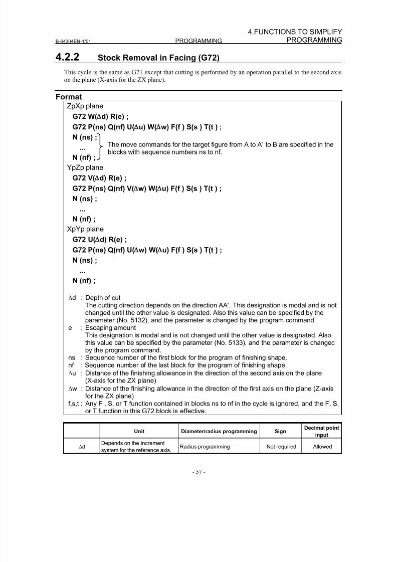
8/16/2019 Manual Operacion para FANUC
http://slidepdf.com/reader/full/manual-operacion-para-fanuc 75/435
B-64304EN-1/01 PROGRAMMING
- 57 -
4.FUNCTIONS TO SIMPLIFYPROGRAMMING
4.2.2 Stock Removal in Facing (G72)
This cycle is the same as G71 except that cutting is performed by an operation parallel to the second axis
on the plane (X-axis for the ZX plane).
FormatZpXp plane
G72 W( d) R(e) ;
G72 P(ns) Q(nf) U( u) W( w) F(f ) S(s ) T(t ) ;
N (ns) ;
...
N (nf) ;
YpZp plane
G72 V( d) R(e) ;
G72 P(ns) Q(nf) V( w) W( u) F(f ) S(s ) T(t ) ;
N (ns) ;
...
N (nf) ;
XpYp plane
G72 U( d) R(e) ;
G72 P(ns) Q(nf) U( w) W( u) F(f ) S(s ) T(t ) ;
N (ns) ;
...
N (nf) ;
Δd : Depth of cutThe cutting direction depends on the direction AA'. This designation is modal and is notchanged until the other value is designated. Also this value can be specified by theparameter (No. 5132), and the parameter is changed by the program command.
e : Escaping amountThis designation is modal and is not changed until the other value is designated. Alsothis value can be specified by the parameter (No. 5133), and the parameter is changed
by the program command.ns : Sequence number of the first block for the program of finishing shape.nf : Sequence number of the last block for the program of finishing shape.
Δu : Distance of the finishing allowance in the direction of the second axis on the plane(X-axis for the ZX plane)
Δw : Distance of the finishing allowance in the direction of the first axis on the plane (Z-axisfor the ZX plane)
f,s,t : Any F , S, or T function contained in blocks ns to nf in the cycle is ignored, and the F, S,or T function in this G72 block is effective.
Unit Diameter/radius programming SignDecimal point
input
ΔdDepends on the increment
system for the reference axis.Radius programming Not required Allowed
The move commands for the target figure from A to A’ to B are specified in theblocks with sequence numbers ns to nf.
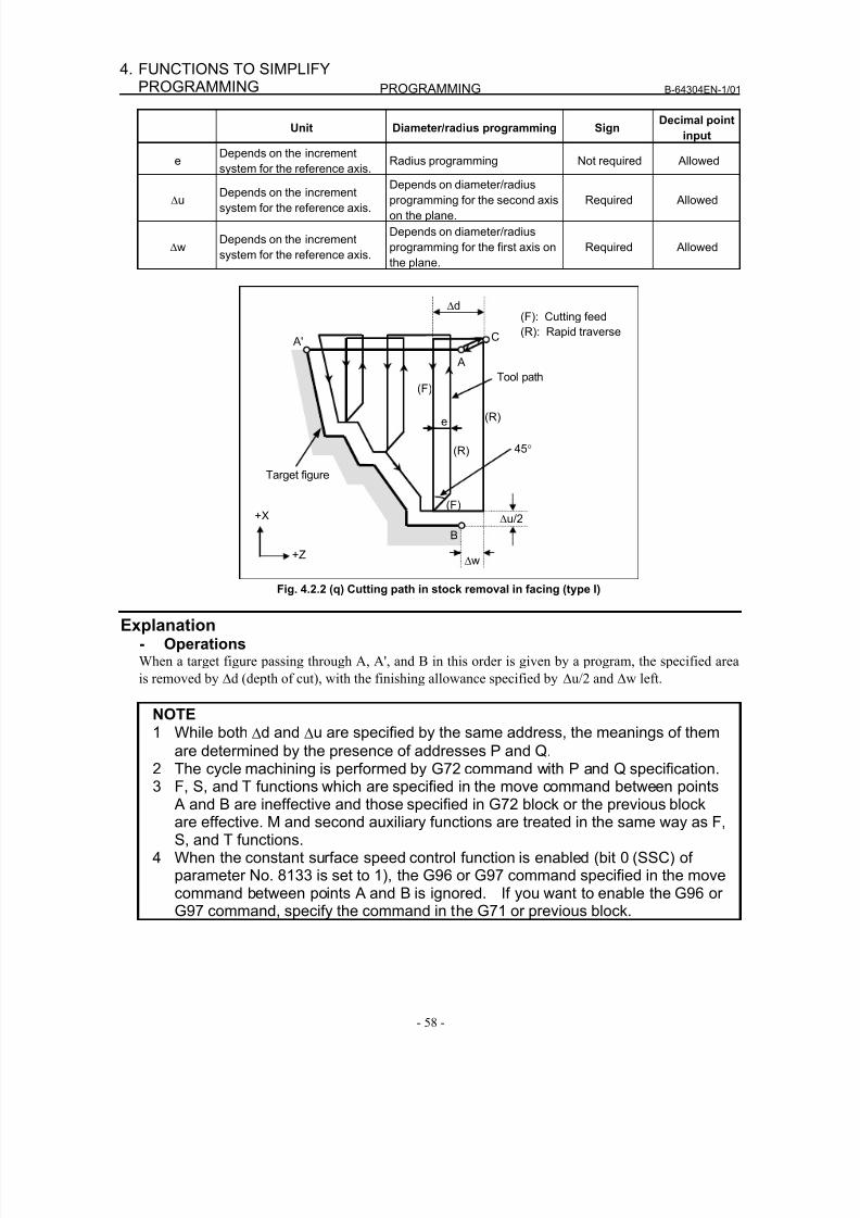
8/16/2019 Manual Operacion para FANUC
http://slidepdf.com/reader/full/manual-operacion-para-fanuc 76/435
PROGRAMMING B-64304EN-1/01
- 58 -
4. FUNCTIONS TO SIMPLIFYPROGRAMMING
Unit Diameter/radius programming SignDecimal point
input
eDepends on the increment
system for the reference axis.Radius programming Not required Allowed
Δu Depends on the incrementsystem for the reference axis.
Depends on diameter/radius
programming for the second axis
on the plane.
Required Allowed
ΔwDepends on the increment
system for the reference axis.
Depends on diameter/radius
programming for the first axis on
the plane.
Required Allowed
A'
Δu/2
Δd
B
Tool path(F)
(R)
e
45°
(R)
(F)
A
C
Δw
Target figure
(F): Cutting feed
(R): Rapid traverse
+X
+Z
Fig. 4.2.2 (q) Cutting path in stock removal in facing (type I)
Explanation- OperationsWhen a target figure passing through A, A', and B in this order is given by a program, the specified area
is removed by Δd (depth of cut), with the finishing allowance specified by Δu/2 and Δw left.
NOTE1 While both Δd and Δu are specified by the same address, the meanings of them
are determined by the presence of addresses P and Q.
2 The cycle machining is performed by G72 command with P and Q specification.3 F, S, and T functions which are specified in the move command between points
A and B are ineffective and those specified in G72 block or the previous blockare effective. M and second auxiliary functions are treated in the same way as F,S, and T functions.
4 When the constant surface speed control function is enabled (bit 0 (SSC) ofparameter No. 8133 is set to 1), the G96 or G97 command specified in the movecommand between points A and B is ignored. If you want to enable the G96 orG97 command, specify the command in the G71 or previous block.
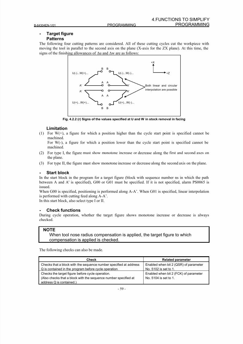
8/16/2019 Manual Operacion para FANUC
http://slidepdf.com/reader/full/manual-operacion-para-fanuc 77/435
B-64304EN-1/01 PROGRAMMING
- 59 -
4.FUNCTIONS TO SIMPLIFYPROGRAMMING
- Target figurePatterns
The following four cutting patterns are considered. All of these cutting cycles cut the workpiece with
moving the tool in parallel to the second axis on the plane (X-axis for the ZX plane). At this time, the
signs of the finishing allowances of Δu and Δw are as follows:
Both linear and circular
interpolation are possible
+X
+Z
B
A
U(-)...W(+)...
A'
B
A
U(-)...W(-)...
A'
B
A
U(+)...W(+)...
A'
B
A
U(+)...W(-)...
A'
Fig. 4.2.2 (r) Signs of the values specified at U and W in stock removal in facing
Limitation(1) For W(+), a figure for which a position higher than the cycle start point is specified cannot be
machined.
For W(-), a figure for which a position lower than the cycle start point is specified cannot be
machined.
(2) For type I, the figure must show monotone increase or decrease along the first and second axes on
the plane.
(3) For type II, the figure must show monotone increase or decrease along the second axis on the plane.
- Start blockIn the start block in the program for a target figure (block with sequence number ns in which the path
between A and A' is specified), G00 or G01 must be specified. If it is not specified, alarm PS0065 is
issued.
When G00 is specified, positioning is performed along A-A’. When G01 is specified, linear interpolation
is performed with cutting feed along A-A’.
In this start block, also select type I or II.
- Check functions
During cycle operation, whether the target figure shows monotone increase or decrease is alwayschecked.
NOTEWhen tool nose radius compensation is applied, the target figure to whichcompensation is applied is checked.
The following checks can also be made.
Check Related parameter
Checks that a block with the sequence number specified at address
Q is contained in the program before cycle operation.
Enabled when bit 2 (QSR) of parameter
No. 5102 is set to 1.Checks the target figure before cycle operation.
(Also checks that a block with the sequence number specified at
address Q is contained.)
Enabled when bit 2 (FCK) of parameter
No. 5104 is set to 1.
8/16/2019 Manual Operacion para FANUC
http://slidepdf.com/reader/full/manual-operacion-para-fanuc 78/435
PROGRAMMING B-64304EN-1/01
- 60 -
4. FUNCTIONS TO SIMPLIFYPROGRAMMING
- Types I and IISelection of type I or II
For G72, there are types I and II.
When the target figure has pockets, be sure to use type II.Escaping operation after rough cutting in the direction of the second axis on the plane (X-axis for the ZX
plane) differs between types I and II. With type I, the tool escapes to the direction of 45 degrees. With
type II, the tool cuts the workpiece along the target figure. When the target figure has no pockets,
determine the desired escaping operation and select type I or II.
Selecting type I or IIIn the start block for the target figure (sequence number ns), select type I or II.
(1) When type I is selected
Specify the first axis on the plane (Z-axis for the ZX plane). Do not specify the second axis on the
plane (X-axis for the ZX plane).
(2) When type II is selectedSpecify the second axis on the plane (X-axis for the ZX plane) and first axis on the plane (Z-axis for
the ZX plane).
When you want to use type II without moving the tool along the second axis on the plane (X-axis for
the ZX plane), specify the incremental programming with travel distance 0 (U0 for the ZX plane).
- Type IG72 differs from G71 in the following points:
(1) G72 cuts the workpiece with moving the tool in parallel with the second axis on the plane (X-axis on
the ZX plane).
(2) In the start block in the program for a target figure (block with sequence number ns), only the first
axis on the plane (Z-axis (W-axis) for the ZX plane) must be specified.
- Type IIG72 differs from G71 in the following points:
(1) G72 cuts the workpiece with moving the tool in parallel with the second axis on the plane (X-axis on
the ZX plane).
(2) The figure need not show monotone increase or decrease in the direction of the first axis on the
plane (Z-axis for the ZX plane) and it may have concaves (pockets). The figure must show
monotone change in the direction of the second axis on the plane (X-axis for the ZX plane),
however.
(3) When a position parallel to the second axis on the plane (X-axis for the ZX plane) is specified in a
block in the program for the target figure, it is assumed to be at the bottom of a pocket.(4) After all rough cutting terminates along the second axis on the plane (X-axis for the ZX plane), the
tool temporarily returns to the start point. Then, rough cutting as finishing is performed.
- Tool nose radius compensationSee the pages on which G71 is explained.
- Movement to the previous turning start pointSee the pages on which G71 is explained.
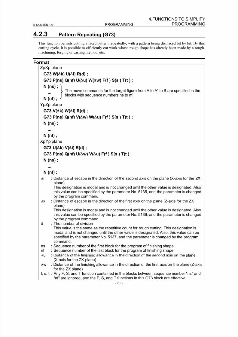
8/16/2019 Manual Operacion para FANUC
http://slidepdf.com/reader/full/manual-operacion-para-fanuc 79/435
B-64304EN-1/01 PROGRAMMING
- 61 -
4.FUNCTIONS TO SIMPLIFYPROGRAMMING
4.2.3 Pattern Repeating (G73)
This function permits cutting a fixed pattern repeatedly, with a pattern being displaced bit by bit. By this
cutting cycle, it is possible to efficiently cut work whose rough shape has already been made by a rough
machining, forging or casting method, etc.
FormatZpXp plane
G73 W( k) U( i) R(d) ;
G73 P(ns) Q(nf) U( u) W( w) F(f ) S(s ) T(t ) ;
N (ns) ;
...
N (nf) ;
YpZp planeG73 V( k) W( i) R(d) ;
G73 P(ns) Q(nf) V( w) W( u) F(f ) S(s ) T(t ) ;
N (ns) ;
...
N (nf) ;
XpYp plane
G73 U( k) V( i) R(d) ;
G73 P(ns) Q(nf) U( w) V( u) F(f ) S(s ) T(t ) ;
N (ns) ;
...
N (nf) ;
Δi : Distance of escape in the direction of the second axis on the plane (X-axis for the ZXplane)This designation is modal and is not changed until the other value is designated. Alsothis value can be specified by the parameter No. 5135, and the parameter is changedby the program command.
Δk : Distance of escape in the direction of the first axis on the plane (Z-axis for the ZXplane)
This designation is modal and is not changed until the other value is designated. Alsothis value can be specified by the parameter No. 5136, and the parameter is changedby the program command.
d : The number of divisionThis value is the same as the repetitive count for rough cutting. This designation ismodal and is not changed until the other value is designated. Also, this value can bespecified by the parameter No. 5137, and the parameter is changed by the programcommand.
ns : Sequence number of the first block for the program of finishing shape.nf : Sequence number of the last block for the program of finishing shape.
Δu : Distance of the finishing allowance in the direction of the second axis on the plane(X-axis for the ZX plane)
Δw : Distance of the finishing allowance in the direction of the first axis on the plane (Z-axisfor the ZX plane)
f, s, t : Any F, S, and T function contained in the blocks between sequence number "ns" and"nf" are ignored, and the F, S, and T functions in this G73 block are effective.
The move commands for the target figure from A to A’ to B are specified in theblocks with sequence numbers ns to nf.
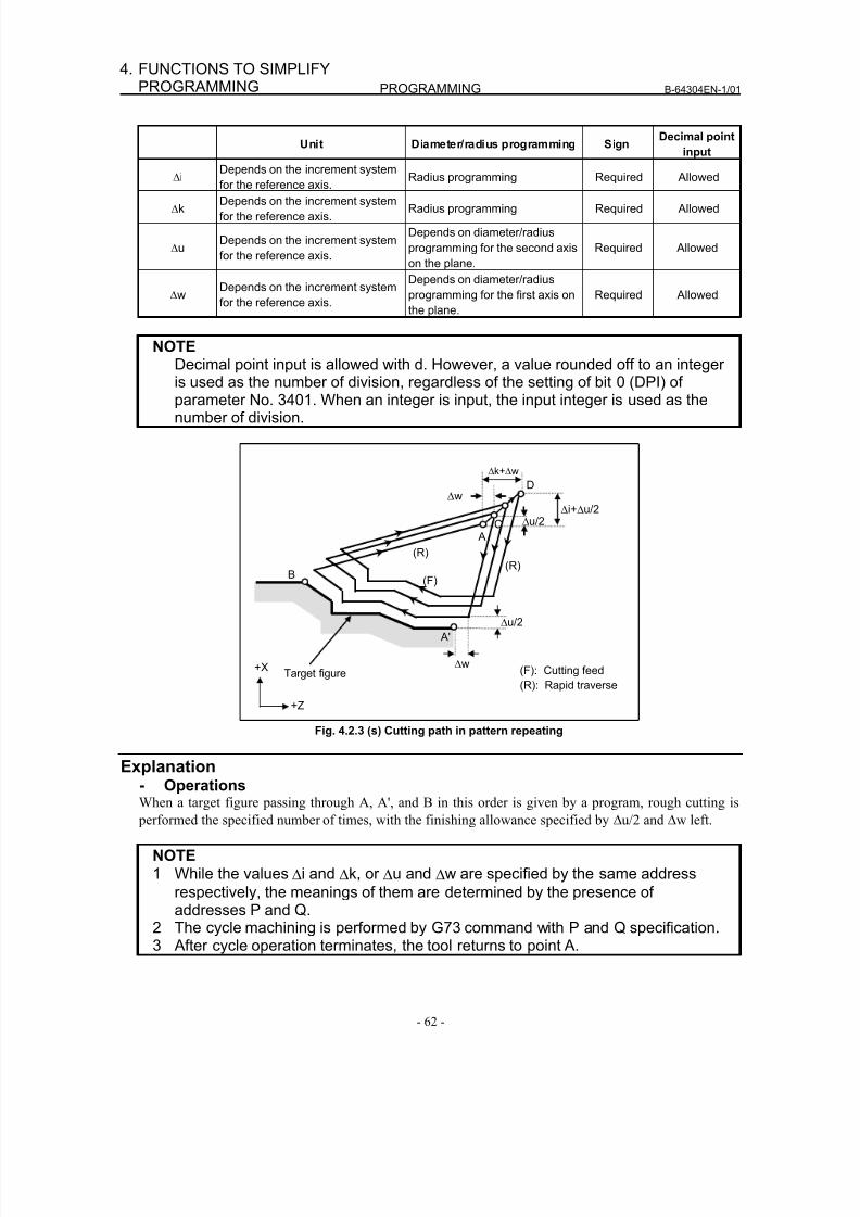
8/16/2019 Manual Operacion para FANUC
http://slidepdf.com/reader/full/manual-operacion-para-fanuc 80/435
PROGRAMMING B-64304EN-1/01
- 62 -
4. FUNCTIONS TO SIMPLIFYPROGRAMMING
Unit Diameter/radius programming SignDecimal point
input
ΔiDepends on the increment system
for the reference axis.
Radius programming Required Allowed
ΔkDepends on the increment system
for the reference axis.Radius programming Required Allowed
ΔuDepends on the increment system
for the reference axis.
Depends on diameter/radius
programming for the second axis
on the plane.
Required Allowed
ΔwDepends on the increment system
for the reference axis.
Depends on diameter/radius
programming for the first axis on
the plane.
Required Allowed
NOTEDecimal point input is allowed with d. However, a value rounded off to an integer
is used as the number of division, regardless of the setting of bit 0 (DPI) ofparameter No. 3401. When an integer is input, the input integer is used as thenumber of division.
Δw
A'
Δu/2 Δi+Δu/2
B
D
Δk+Δw
C
Δw
Δu/2
Target figure (F): Cutting feed
(R): Rapid traverse
(R)
+X
+Z
(R)
A
(F)
Fig. 4.2.3 (s) Cutting path in pattern repeating
Explanation- OperationsWhen a target figure passing through A, A', and B in this order is given by a program, rough cutting is
performed the specified number of times, with the finishing allowance specified by Δu/2 and Δw left.
NOTE1 While the values Δi and Δk, or Δu and Δw are specified by the same address
respectively, the meanings of them are determined by the presence ofaddresses P and Q.
2 The cycle machining is performed by G73 command with P and Q specification.3 After cycle operation terminates, the tool returns to point A.
8/16/2019 Manual Operacion para FANUC
http://slidepdf.com/reader/full/manual-operacion-para-fanuc 81/435
B-64304EN-1/01 PROGRAMMING
- 63 -
4.FUNCTIONS TO SIMPLIFYPROGRAMMING
NOTE4 F, S, and T functions which are specified in the move command between points
A and B are ineffective and those specified in G73 block or the previous blockare effective. M and second auxiliary functions are treated in the same way as F,
S, and T functions.
- Target figurePatterns
As in the case of G71, there are four target figure patterns. Be careful about signs of Δu, Δw, Δi, and Δk
when programming this cycle.
- Start blockIn the start block in the program for the target figure (block with sequence number ns in which the path
between A and A' is specified), G00 or G01 must be specified. If it is not specified, alarm PS0065 is
issued.
When G00 is specified, positioning is performed along A-A’. When G01 is specified, linear interpolationis performed with cutting feed along A-A’.
- Check functionThe following check can be made.
Check Related parameter
Checks that a block with the sequence number specified at address
Q is contained in the program before cycle operation.
Enabled when bit 2 (QSR) of parameter
No. 5102 is set to 1.
- Tool nose radius compensation
Like G71, this cycle operation is performed according to the figure determined by the tool nose radiuscompensation path when the offset vector is 0 at start point A and start-up is performed in a block
between path A-A'.
4.2.4 Finishing Cycle (G70)
After rough cutting by G71, G72 or G73, the following command permits finishing.
FormatG70 P(ns) Q(nf) ;
ns : Sequence number of the first block for the program of finishing shape.
nf : Sequence number of the last block for the program of finishing shape.
Explanation- OperationsThe blocks with sequence numbers ns to nf in the program for a target figure are executed for finishing.
The F, S, T, M, and second auxiliary functions specified in the G71, G72, or G73 block are ignored and
the F, S, T, M, and second auxiliary functions specified in the blocks with sequence numbers ns to nf are
effective.
When cycle operation terminates, the tool is returned to the start point in rapid traverse and the next G70
cycle block is read.
- Target figureCheck function
The following check can be made.
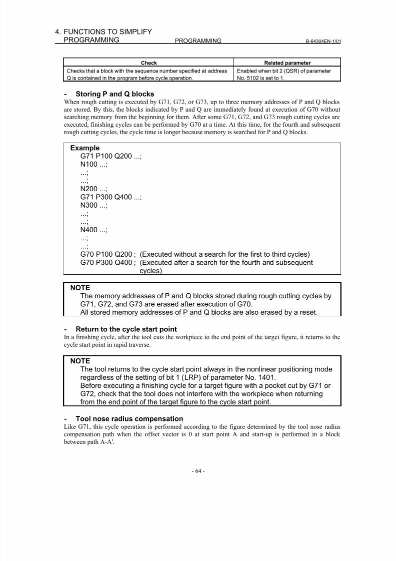
8/16/2019 Manual Operacion para FANUC
http://slidepdf.com/reader/full/manual-operacion-para-fanuc 82/435
PROGRAMMING B-64304EN-1/01
- 64 -
4. FUNCTIONS TO SIMPLIFYPROGRAMMING
Check Related parameter
Checks that a block with the sequence number specified at address
Q is contained in the program before cycle operation.
Enabled when bit 2 (QSR) of parameter
No. 5102 is set to 1.
- Storing P and Q blocksWhen rough cutting is executed by G71, G72, or G73, up to three memory addresses of P and Q blocks
are stored. By this, the blocks indicated by P and Q are immediately found at execution of G70 without
searching memory from the beginning for them. After some G71, G72, and G73 rough cutting cycles are
executed, finishing cycles can be performed by G70 at a time. At this time, for the fourth and subsequent
rough cutting cycles, the cycle time is longer because memory is searched for P and Q blocks.
ExampleG71 P100 Q200 ...;N100 ...;
...;...;N200 ...;G71 P300 Q400 ...;N300 ...;...;...;N400 ...;...;...;G70 P100 Q200 ; (Executed without a search for the first to third cycles)
G70 P300 Q400 ; (Executed after a search for the fourth and subsequentcycles)
NOTEThe memory addresses of P and Q blocks stored during rough cutting cycles byG71, G72, and G73 are erased after execution of G70. All stored memory addresses of P and Q blocks are also erased by a reset.
- Return to the cycle start pointIn a finishing cycle, after the tool cuts the workpiece to the end point of the target figure, it returns to the
cycle start point in rapid traverse.
NOTEThe tool returns to the cycle start point always in the nonlinear positioning moderegardless of the setting of bit 1 (LRP) of parameter No. 1401.Before executing a finishing cycle for a target figure with a pocket cut by G71 orG72, check that the tool does not interfere with the workpiece when returningfrom the end point of the target figure to the cycle start point.
- Tool nose radius compensationLike G71, this cycle operation is performed according to the figure determined by the tool nose radius
compensation path when the offset vector is 0 at start point A and start-up is performed in a block
between path A-A'.
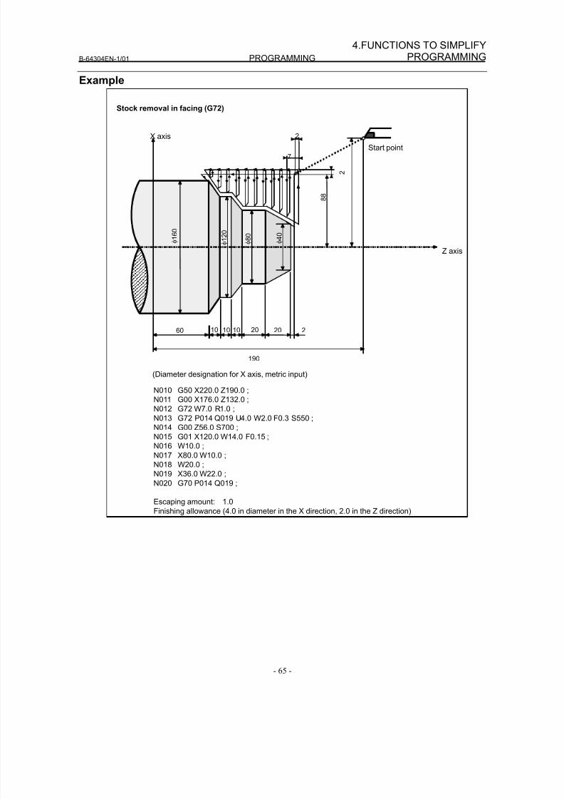
8/16/2019 Manual Operacion para FANUC
http://slidepdf.com/reader/full/manual-operacion-para-fanuc 83/435
B-64304EN-1/01 PROGRAMMING
- 65 -
4.FUNCTIONS TO SIMPLIFYPROGRAMMING
Example
Stock removal in facing (G72)
(Diameter designation for X axis, metric input)
N010 G50 X220.0 Z190.0 ;
N011 G00 X176.0 Z132.0 ;
N012 G72 W7.0 R1.0 ;
N013 G72 P014 Q019 U4.0 W2.0 F0.3 S550 ;
N014 G00 Z56.0 S700 ;
N015 G01 X120.0 W14.0 F0.15 ;
N016 W10.0 ;
N017 X80.0 W10.0 ;
N018 W20.0 ;
N019 X36.0 W22.0 ;
N020 G70 P014 Q019 ;
Escaping amount: 1.0Finishing allowance (4.0 in diameter in the X direction, 2.0 in the Z direction)
φ 1 2 0
φ 8 0
φ 4 0
φ 1 6 0
20 2
8 8
Start point
Z axis
X axis
201060 10
190
7
2
2
10
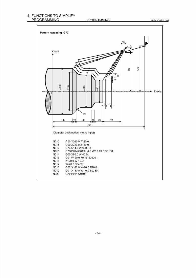
8/16/2019 Manual Operacion para FANUC
http://slidepdf.com/reader/full/manual-operacion-para-fanuc 84/435
PROGRAMMING B-64304EN-1/01
- 66 -
4. FUNCTIONS TO SIMPLIFYPROGRAMMING
Pattern repeating (G73)
(Diameter designation, metric input)
φ 8 0
φ 1 8 0
Z axis
X axis
220
B
2
1 3 0
1 6
16
1 1 0
1 4
φ 1 6 0
2 14
0
20
φ 1 2
0
40 10 40 20 4010
N010 G50 X260.0 Z220.0 ;
N011 G00 X220.0 Z160.0 ;
N012 G73 U14.0 W14.0 R3 ;
N013 G73 P014 Q019 U4.0 W2.0 F0.3 S0180 ;
N014 G00 X80.0 W-40.0 ;
N015 G01 W-20.0 F0.15 S0600 ;
N016 X120.0 W-10.0;
N017 W-20.0 S0400 ;
N018 G02 X160.0 W-20.0 R20.0 ;
N019 G01 X180.0 W-10.0 S0280 ;
N020 G70 P014 Q019 ;
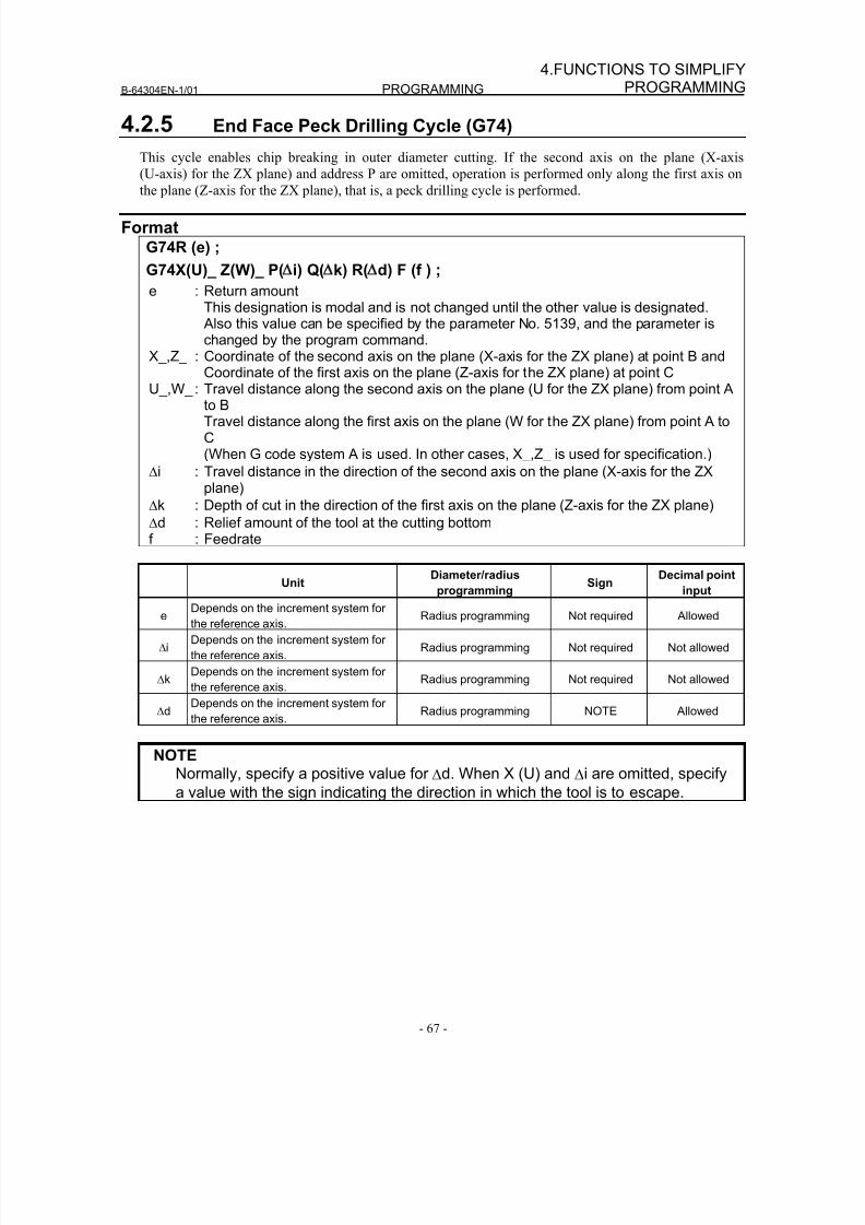
8/16/2019 Manual Operacion para FANUC
http://slidepdf.com/reader/full/manual-operacion-para-fanuc 85/435
B-64304EN-1/01 PROGRAMMING
- 67 -
4.FUNCTIONS TO SIMPLIFYPROGRAMMING
4.2.5 End Face Peck Drilling Cycle (G74)
This cycle enables chip breaking in outer diameter cutting. If the second axis on the plane (X-axis
(U-axis) for the ZX plane) and address P are omitted, operation is performed only along the first axis on
the plane (Z-axis for the ZX plane), that is, a peck drilling cycle is performed.
FormatG74R (e) ;
G74X(U)_ Z(W)_ P( i) Q( k) R( d) F (f ) ;
e : Return amountThis designation is modal and is not changed until the other value is designated. Also this value can be specified by the parameter No. 5139, and the parameter ischanged by the program command.
X_,Z_ : Coordinate of the second axis on the plane (X-axis for the ZX plane) at point B andCoordinate of the first axis on the plane (Z-axis for the ZX plane) at point C
U_,W_ : Travel distance along the second axis on the plane (U for the ZX plane) from point Ato BTravel distance along the first axis on the plane (W for the ZX plane) from point A toC(When G code system A is used. In other cases, X_,Z_ is used for specification.)
Δi : Travel distance in the direction of the second axis on the plane (X-axis for the ZXplane)
Δk : Depth of cut in the direction of the first axis on the plane (Z-axis for the ZX plane)
Δd : Relief amount of the tool at the cutting bottomf : Feedrate
Unit Diameter/radiusprogramming
Sign Decimal pointinput
eDepends on the increment system for
the reference axis.Radius programming Not required Allowed
ΔiDepends on the increment system for
the reference axis.Radius programming Not required Not allowed
ΔkDepends on the increment system for
the reference axis.Radius programming Not required Not allowed
ΔdDepends on the increment system for
the reference axis.Radius programming NOTE Allowed
NOTE
Normally, specify a positive value for Δd. When X (U) and Δi are omitted, specifya value with the sign indicating the direction in which the tool is to escape.
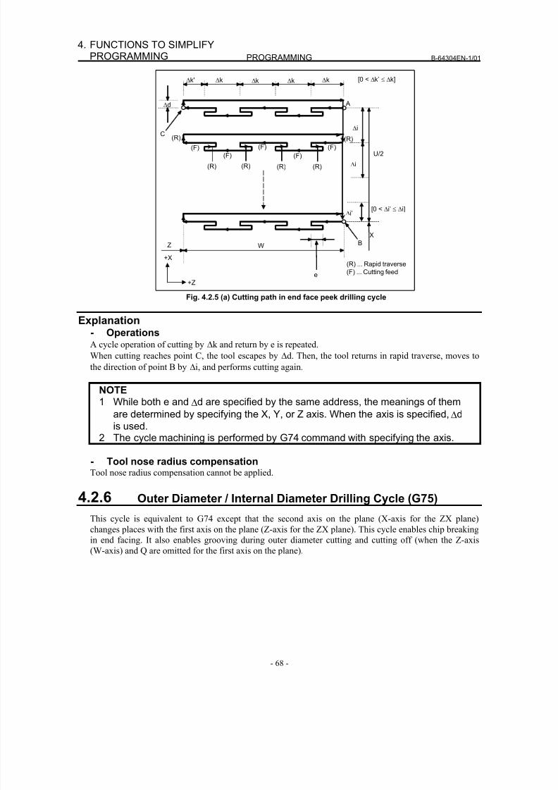
8/16/2019 Manual Operacion para FANUC
http://slidepdf.com/reader/full/manual-operacion-para-fanuc 86/435
PROGRAMMING B-64304EN-1/01
- 68 -
4. FUNCTIONS TO SIMPLIFYPROGRAMMING
U/2
W
Δd
Δi’
C
Δk' Δk Δk Δk Δk
A
(R)
(R)
(F)
(R)(R)(R)
(F)
(F)
(F)
(F)
Δi
Δi
e
B
[0 < Δk’ ≤ Δk]
X
Z
(R)
[0 < Δi’ ≤ Δi]
(R) ... Rapid traverse
(F) ... Cutting feed
+X
+Z
Fig. 4.2.5 (a) Cutting path in end face peek drilling cycle
Explanation- OperationsA cycle operation of cutting by Δk and return by e is repeated.
When cutting reaches point C, the tool escapes by Δd. Then, the tool returns in rapid traverse, moves to
the direction of point B by Δi, and performs cutting again.
NOTE1 While both e and Δd are specified by the same address, the meanings of them
are determined by specifying the X, Y, or Z axis. When the axis is specified, Δd
is used.2 The cycle machining is performed by G74 command with specifying the axis.
- Tool nose radius compensationTool nose radius compensation cannot be applied.
4.2.6 Outer Diameter / Internal Diameter Drilling Cycle (G75)
This cycle is equivalent to G74 except that the second axis on the plane (X-axis for the ZX plane)
changes places with the first axis on the plane (Z-axis for the ZX plane). This cycle enables chip breaking
in end facing. It also enables grooving during outer diameter cutting and cutting off (when the Z-axis
(W-axis) and Q are omitted for the first axis on the plane).
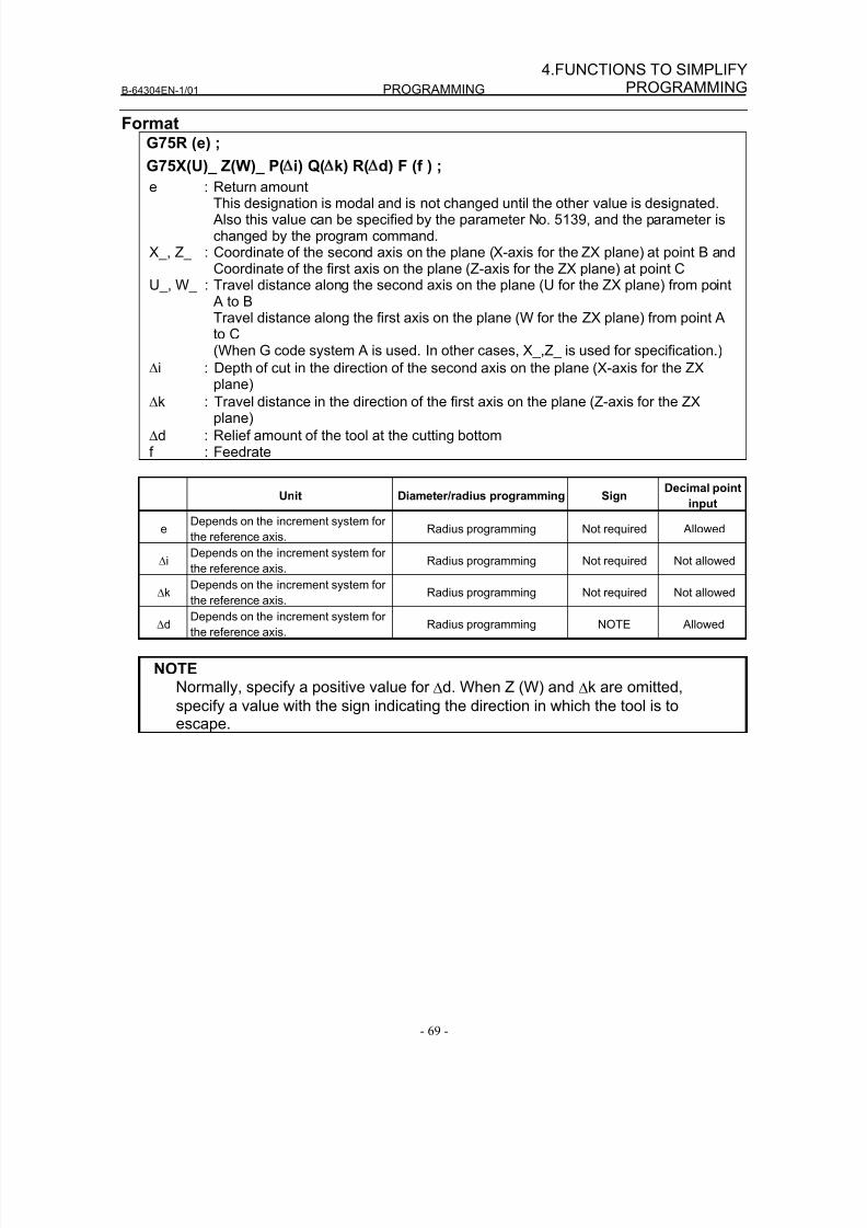
8/16/2019 Manual Operacion para FANUC
http://slidepdf.com/reader/full/manual-operacion-para-fanuc 87/435
B-64304EN-1/01 PROGRAMMING
- 69 -
4.FUNCTIONS TO SIMPLIFYPROGRAMMING
FormatG75R (e) ;
G75X(U)_ Z(W)_ P( i) Q( k) R( d) F (f ) ;
e : Return amountThis designation is modal and is not changed until the other value is designated. Also this value can be specified by the parameter No. 5139, and the parameter ischanged by the program command.
X_, Z_ : Coordinate of the second axis on the plane (X-axis for the ZX plane) at point B and Coordinate of the first axis on the plane (Z-axis for the ZX plane) at point CU_, W_ : Travel distance along the second axis on the plane (U for the ZX plane) from point
A to BTravel distance along the first axis on the plane (W for the ZX plane) from point Ato C(When G code system A is used. In other cases, X_,Z_ is used for specification.)
Δi : Depth of cut in the direction of the second axis on the plane (X-axis for the ZX
plane)Δk : Travel distance in the direction of the first axis on the plane (Z-axis for the ZX
plane)
Δd : Relief amount of the tool at the cutting bottomf : Feedrate
Unit Diameter/radius programming SignDecimal point
input
eDepends on the increment system for
the reference axis.Radius programming Not required Allowed
ΔiDepends on the increment system for
the reference axis.Radius programming Not required Not allowed
ΔkDepends on the increment system for
the reference axis.Radius programming Not required Not allowed
ΔdDepends on the increment system for
the reference axis.Radius programming NOTE Allowed
NOTENormally, specify a positive value for Δd. When Z (W) and Δk are omitted,
specify a value with the sign indicating the direction in which the tool is toescape.
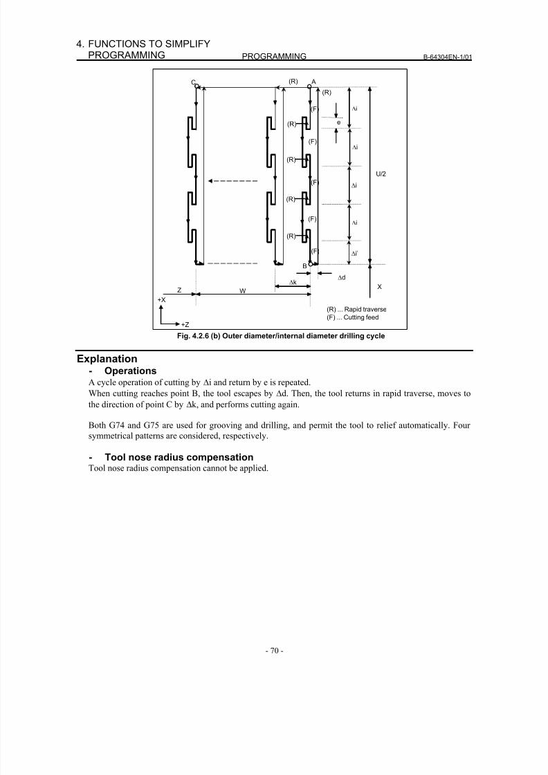
8/16/2019 Manual Operacion para FANUC
http://slidepdf.com/reader/full/manual-operacion-para-fanuc 88/435
PROGRAMMING B-64304EN-1/01
- 70 -
4. FUNCTIONS TO SIMPLIFYPROGRAMMING
W
Δd
A
(R)
(F) Δi
e
Z
Δk X
(F)
(F)
(F)
(F)
(R)
U/2
(R) ... Rapid traverse
(F) ... Cutting feed
(R)
B
C
Δi
Δi
Δi
+X
+Z
Δi’
(R)
(R)
(R)
Fig. 4.2.6 (b) Outer diameter/internal diameter drilling cycle
Explanation- OperationsA cycle operation of cutting by Δi and return by e is repeated.
When cutting reaches point B, the tool escapes by Δd. Then, the tool returns in rapid traverse, moves to
the direction of point C by Δk, and performs cutting again.
Both G74 and G75 are used for grooving and drilling, and permit the tool to relief automatically. Four
symmetrical patterns are considered, respectively.
- Tool nose radius compensationTool nose radius compensation cannot be applied.
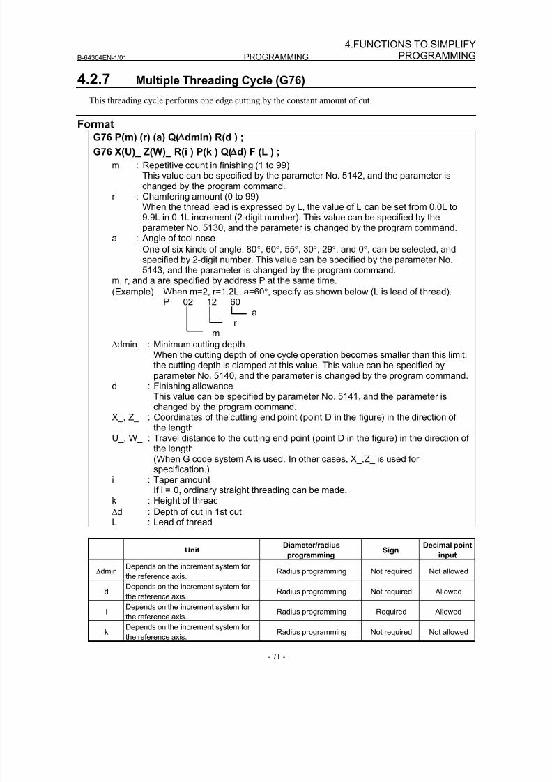
8/16/2019 Manual Operacion para FANUC
http://slidepdf.com/reader/full/manual-operacion-para-fanuc 89/435
B-64304EN-1/01 PROGRAMMING
- 71 -
4.FUNCTIONS TO SIMPLIFYPROGRAMMING
4.2.7 Multiple Threading Cycle (G76)
This threading cycle performs one edge cutting by the constant amount of cut.
FormatG76 P(m) (r) (a) Q( dmin) R(d ) ;
G76 X(U)_ Z(W)_ R(i ) P(k ) Q( d) F (L ) ;
m : Repetitive count in finishing (1 to 99)This value can be specified by the parameter No. 5142, and the parameter ischanged by the program command.
r : Chamfering amount (0 to 99)When the thread lead is expressed by L, the value of L can be set from 0.0L to9.9L in 0.1L increment (2-digit number). This value can be specified by theparameter No. 5130, and the parameter is changed by the program command.
a : Angle of tool nose
One of six kinds of angle, 80°, 60°, 55°, 30°, 29°, and 0°, can be selected, andspecified by 2-digit number. This value can be specified by the parameter No.5143, and the parameter is changed by the program command.
m, r, and a are specified by address P at the same time.
(Example) When m=2, r=1.2L, a=60°, specify as shown below (L is lead of thread).P 02 12 60
ar
m
Δdmin : Minimum cutting depthWhen the cutting depth of one cycle operation becomes smaller than this limit,
the cutting depth is clamped at this value. This value can be specified byparameter No. 5140, and the parameter is changed by the program command.d : Finishing allowance
This value can be specified by parameter No. 5141, and the parameter ischanged by the program command.
X_, Z_ : Coordinates of the cutting end point (point D in the figure) in the direction ofthe length
U_, W_ : Travel distance to the cutting end point (point D in the figure) in the direction ofthe length(When G code system A is used. In other cases, X_,Z_ is used forspecification.)
i : Taper amount
If i = 0, ordinary straight threading can be made.k : Height of thread
Δd : Depth of cut in 1st cutL : Lead of thread
UnitDiameter/radius
programmingSign
Decimal point
input
ΔdminDepends on the increment system for
the reference axis.Radius programming Not required Not allowed
dDepends on the increment system for
the reference axis.Radius programming Not required Allowed
i
Depends on the increment system for
the reference axis. Radius programming Required Allowed
kDepends on the increment system for
the reference axis.Radius programming Not required Not allowed
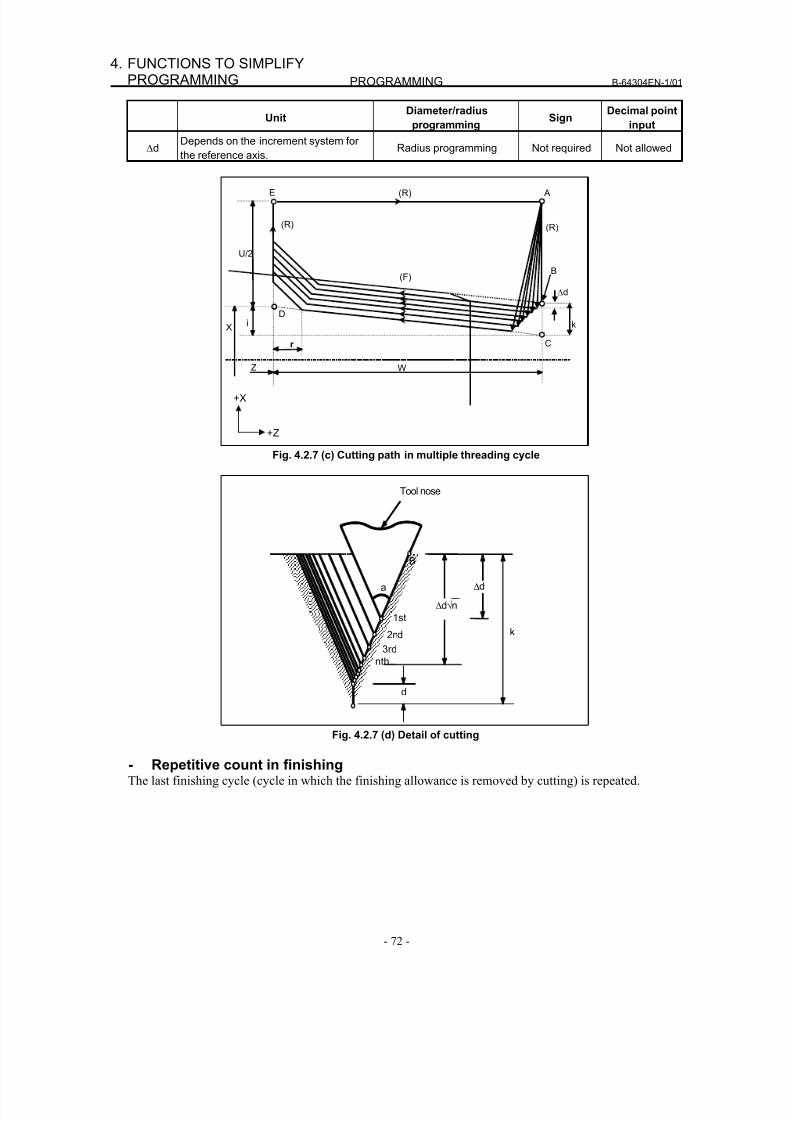
8/16/2019 Manual Operacion para FANUC
http://slidepdf.com/reader/full/manual-operacion-para-fanuc 90/435
PROGRAMMING B-64304EN-1/01
- 72 -
4. FUNCTIONS TO SIMPLIFYPROGRAMMING
UnitDiameter/radius
programmingSign
Decimal point
input
ΔdDepends on the increment system for
the reference axis.Radius programming Not required Not allowed
W
C
(F)
(R) A
U/2
Δd
E
i X
Z
r
Dk
(R)
B
+X
+Z
(R)
Fig. 4.2.7 (c) Cutting path in multiple threading cycle
k
Δd
Δd√n
1st
3rd
2nd
nth
Tool nose
a
B
d
Fig. 4.2.7 (d) Detail of cutting
- Repetitive count in finishingThe last finishing cycle (cycle in which the finishing allowance is removed by cutting) is repeated.
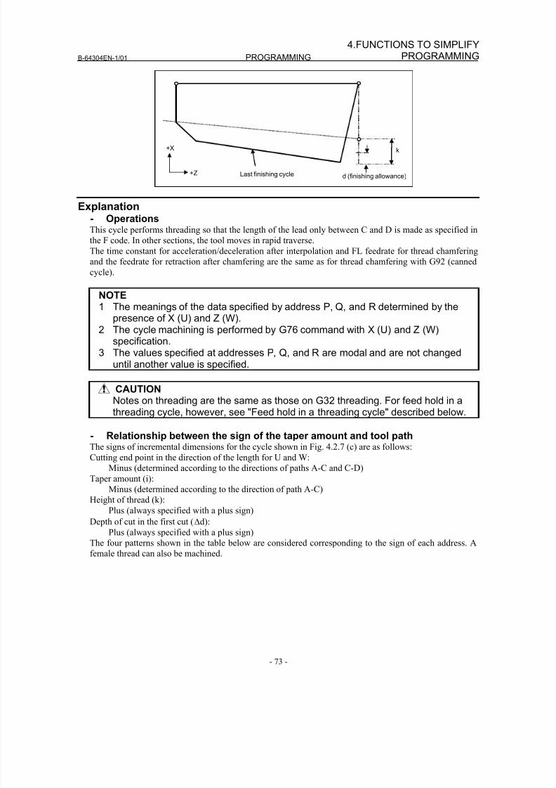
8/16/2019 Manual Operacion para FANUC
http://slidepdf.com/reader/full/manual-operacion-para-fanuc 91/435
B-64304EN-1/01 PROGRAMMING
- 73 -
4.FUNCTIONS TO SIMPLIFYPROGRAMMING
+X
+Z
k
d (finishing allowance)Last finishing cycle
Explanation- OperationsThis cycle performs threading so that the length of the lead only between C and D is made as specified in
the F code. In other sections, the tool moves in rapid traverse.
The time constant for acceleration/deceleration after interpolation and FL feedrate for thread chamfering
and the feedrate for retraction after chamfering are the same as for thread chamfering with G92 (canned
cycle).
NOTE1 The meanings of the data specified by address P, Q, and R determined by the
presence of X (U) and Z (W).2 The cycle machining is performed by G76 command with X (U) and Z (W)
specification.3 The values specified at addresses P, Q, and R are modal and are not changed
until another value is specified.
CAUTIONNotes on threading are the same as those on G32 threading. For feed hold in athreading cycle, however, see "Feed hold in a threading cycle" described below.
- Relationship between the sign of the taper amount and tool pathThe signs of incremental dimensions for the cycle shown in Fig. 4.2.7 (c) are as follows:
Cutting end point in the direction of the length for U and W:
Minus (determined according to the directions of paths A-C and C-D)
Taper amount (i):
Minus (determined according to the direction of path A-C)
Height of thread (k):
Plus (always specified with a plus sign)
Depth of cut in the first cut (Δd):
Plus (always specified with a plus sign)
The four patterns shown in the table below are considered corresponding to the sign of each address. A
female thread can also be machined.
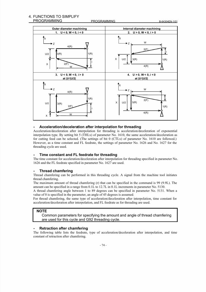
8/16/2019 Manual Operacion para FANUC
http://slidepdf.com/reader/full/manual-operacion-para-fanuc 92/435
PROGRAMMING B-64304EN-1/01
- 74 -
4. FUNCTIONS TO SIMPLIFYPROGRAMMING
Outer diameter machining Internal diameter machining
1. U < 0, W < 0, i < 0 2. U > 0, W < 0, i > 0
X
Z
U/2 3(R)
4(R)
1(R)
2(F)
W
iX
X
Z
U/2 3(R)
4(R)
1(R)
2(F)
W
i
X
3. U < 0, W < 0, i > 0
at |i|≤
|U/2|
4. U > 0, W < 0, i < 0
at |i|≤
|U/2|
X
Z
U/2 3(R)
4(R)
1(R)
2(F)
W
i
X
X
Z
U/2 3(R)
4(R)
1(R)
2(F)
W
i
X
- Acceleration/deceleration after interpolation for threadingAcceleration/deceleration after interpolation for threading is acceleration/deceleration of exponential
interpolation type. By setting bit 5 (THLx) of parameter No. 1610, the same acceleration/deceleration as
for cutting feed can be selected. (The settings of bit 0 (CTLx) of parameter No. 1610 are followed.)However, as a time constant and FL feedrate, the settings of parameter No. 1626 and No. 1627 for the
threading cycle are used.
- Time constant and FL feedrate for threadingThe time constant for acceleration/deceleration after interpolation for threading specified in parameter No.
1626 and the FL feedrate specified in parameter No. 1627 are used.
- Thread chamferingThread chamfering can be performed in this threading cycle. A signal from the machine tool initiates
thread chamfering.
The maximum amount of thread chamfering (r) that can be specified in the command is 99 (9.9L). Theamount can be specified in a range from 0.1L to 12.7L in 0.1L increments in parameter No. 5130.
A thread chamfering angle between 1 to 89 degrees can be specified in parameter No. 5131. When a
value of 0 is specified in the parameter, an angle of 45 degrees is assumed.
For thread chamfering, the same type of acceleration/deceleration after interpolation, time constant for
acceleration/deceleration after interpolation, and FL feedrate as for threading are used.
NOTECommon parameters for specifying the amount and angle of thread chamferingare used for this cycle and G92 threading cycle.
- Retraction after chamferingThe following table lists the feedrate, type of acceleration/deceleration after interpolation, and time
constant of retraction after chamfering.
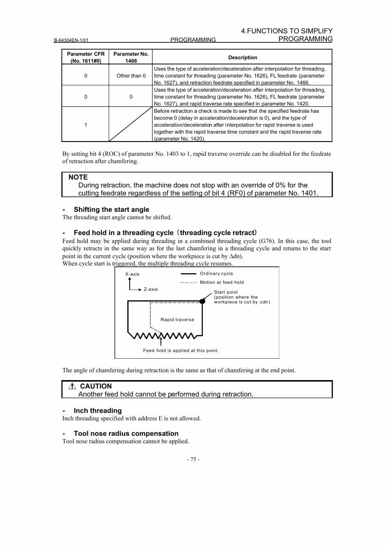
8/16/2019 Manual Operacion para FANUC
http://slidepdf.com/reader/full/manual-operacion-para-fanuc 93/435
B-64304EN-1/01 PROGRAMMING
- 75 -
4.FUNCTIONS TO SIMPLIFYPROGRAMMING
Parameter CFR
(No. 1611#0)
Parameter No.
1466Description
0 Other than 0
Uses the type of acceleration/deceleration after interpolation for threading,
time constant for threading (parameter No. 1626), FL feedrate (parameter
No. 1627), and retraction feedrate specified in parameter No. 1466.
0 0
Uses the type of acceleration/deceleration after interpolation for threading,
time constant for threading (parameter No. 1626), FL feedrate (parameter
No. 1627), and rapid traverse rate specified in parameter No. 1420.
1
Before retraction a check is made to see that the specified feedrate has
become 0 (delay in acceleration/deceleration is 0), and the type of
acceleration/deceleration after interpolation for rapid traverse is used
together with the rapid traverse time constant and the rapid traverse rate
(parameter No. 1420).
By setting bit 4 (ROC) of parameter No. 1403 to 1, rapid traverse override can be disabled for the feedrate
of retraction after chamfering.
NOTEDuring retraction, the machine does not stop with an override of 0% for thecutting feedrate regardless of the setting of bit 4 (RF0) of parameter No. 1401.
- Shifting the start angleThe threading start angle cannot be shifted.
- Feed hold in a threading cycle threading cycle retract) Feed hold may be applied during threading in a combined threading cycle (G76). In this case, the tool
quickly retracts in the same way as for the last chamfering in a threading cycle and returns to the start
point in the current cycle (position where the workpiece is cut by Δdn).When cycle start is triggered, the multiple threading cycle resumes.
Feed hold is applied at this point.
Start point(position where theworkpiece is cut by Δdn )
Ordinary cycle
Rapid traverse
Motion at feed hold
X-axis
Z-axis
The angle of chamfering during retraction is the same as that of chamfering at the end point.
CAUTION Another feed hold cannot be performed during retraction.
- Inch threadingInch threading specified with address E is not allowed.
- Tool nose radius compensationTool nose radius compensation cannot be applied.
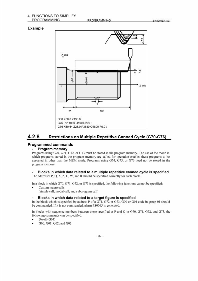
8/16/2019 Manual Operacion para FANUC
http://slidepdf.com/reader/full/manual-operacion-para-fanuc 94/435
PROGRAMMING B-64304EN-1/01
- 76 -
4. FUNCTIONS TO SIMPLIFYPROGRAMMING
Example
G80 X80.0 Z130.0; G76 P011060 Q100 R200 ; G76 X60.64 Z25.0 P3680 Q1800 F6.0 ;
1 .
8
3 .
6 8
6
10525
1 .
8
0
X axis
Z axis
ϕ 6 8
ϕ 6 0 .
6 4
4.2.8 Restrictions on Multiple Repetitive Canned Cycle (G70-G76)
Programmed commands- Program memoryPrograms using G70, G71, G72, or G73 must be stored in the program memory. The use of the mode in
which programs stored in the program memory are called for operation enables these programs to be
executed in other than the MEM mode. Programs using G74, G75, or G76 need not be stored in the
program memory.
- Blocks in which data related to a multiple repetitive canned cycle is specified
The addresses P, Q, X, Z, U, W, and R should be specified correctly for each block.
In a block in which G70, G71, G72, or G73 is specified, the following functions cannot be specified:
• Custom macro calls
(simple call, modal call, and subprogram call)
- Blocks in which data related to a target figure is specifiedIn the block which is specified by address P of a G71, G72 or G73, G00 or G01 code in group 01 should
be commanded. If it is not commanded, alarm PS0065 is generated.
In blocks with sequence numbers between those specified at P and Q in G70, G71, G72, and G73, the
following commands can be specified:
• Dwell (G04)• G00, G01, G02, and G03
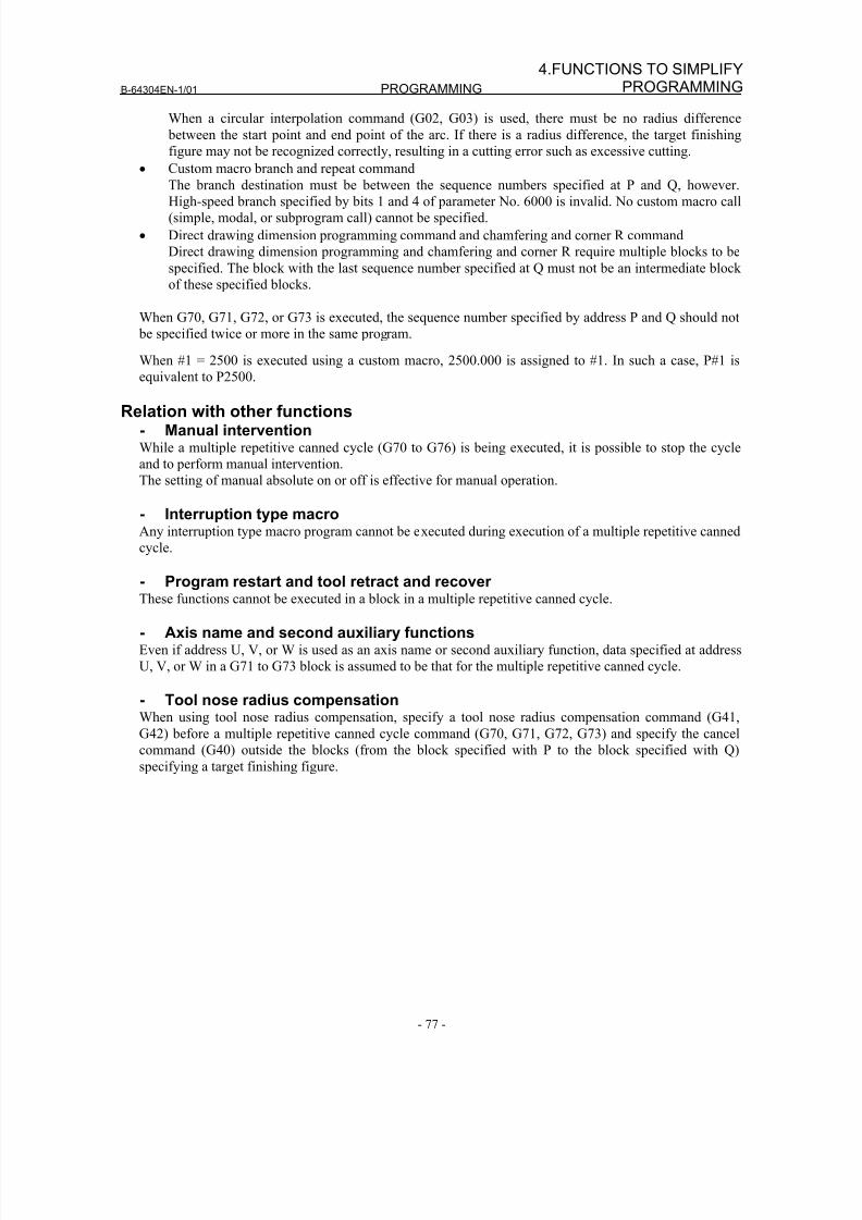
8/16/2019 Manual Operacion para FANUC
http://slidepdf.com/reader/full/manual-operacion-para-fanuc 95/435
B-64304EN-1/01 PROGRAMMING
- 77 -
4.FUNCTIONS TO SIMPLIFYPROGRAMMING
When a circular interpolation command (G02, G03) is used, there must be no radius difference
between the start point and end point of the arc. If there is a radius difference, the target finishing
figure may not be recognized correctly, resulting in a cutting error such as excessive cutting.
• Custom macro branch and repeat command
The branch destination must be between the sequence numbers specified at P and Q, however.High-speed branch specified by bits 1 and 4 of parameter No. 6000 is invalid. No custom macro call
(simple, modal, or subprogram call) cannot be specified.
• Direct drawing dimension programming command and chamfering and corner R command
Direct drawing dimension programming and chamfering and corner R require multiple blocks to be
specified. The block with the last sequence number specified at Q must not be an intermediate block
of these specified blocks.
When G70, G71, G72, or G73 is executed, the sequence number specified by address P and Q should not
be specified twice or more in the same program.
When #1 = 2500 is executed using a custom macro, 2500.000 is assigned to #1. In such a case, P#1 is
equivalent to P2500.
Relation with other functions- Manual interventionWhile a multiple repetitive canned cycle (G70 to G76) is being executed, it is possible to stop the cycle
and to perform manual intervention.
The setting of manual absolute on or off is effective for manual operation.
- Interruption type macroAny interruption type macro program cannot be executed during execution of a multiple repetitive canned
cycle.
- Program restart and tool retract and recoverThese functions cannot be executed in a block in a multiple repetitive canned cycle.
- Axis name and second auxiliary functionsEven if address U, V, or W is used as an axis name or second auxiliary function, data specified at address
U, V, or W in a G71 to G73 block is assumed to be that for the multiple repetitive canned cycle.
- Tool nose radius compensationWhen using tool nose radius compensation, specify a tool nose radius compensation command (G41,
G42) before a multiple repetitive canned cycle command (G70, G71, G72, G73) and specify the cancel
command (G40) outside the blocks (from the block specified with P to the block specified with Q)
specifying a target finishing figure.
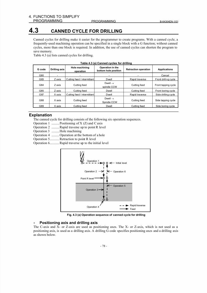
8/16/2019 Manual Operacion para FANUC
http://slidepdf.com/reader/full/manual-operacion-para-fanuc 96/435
PROGRAMMING B-64304EN-1/01
- 78 -
4. FUNCTIONS TO SIMPLIFYPROGRAMMING
4.3 CANNED CYCLE FOR DRILLING
Canned cycles for drilling make it easier for the programmer to create programs. With a canned cycle, a
frequently-used machining operation can be specified in a single block with a G function; without canned
cycles, more than one block is required. In addition, the use of canned cycles can shorten the program to
save memory.
Table 4.3 (a) lists canned cycles for drilling.
Table 4.3 (a) Canned cycles for drilling
G code Drilling axisHole machining
operation
Operation in the
bottom hole positionRetraction operation Applications
G80 - - - - Cancel
G83 Z axis Cutting feed / intermittent Dwell Rapid traverse Front drilling cycle
G84 Z axis Cutting feedDwell →
spindle CCWCutting feed Front tapping cycle
G85 Z axis Cutting feed Dwell Cutting feed Front boring cycleG87 X axis Cutting feed / intermittent Dwell Rapid traverse Side drilling cycle
G88 X axis Cutting feedDwell →
Spindle CCWCutting feed Side tapping cycle
G89 X axis Cutting feed Dwell Cutting feed Side boring cycle
ExplanationThe canned cycle for drilling consists of the following six operation sequences.
Operation 1 ......... Positioning of X (Z) and C axis
Operation 2 .........Rapid traverse up to point R level
Operation 3 .........Hole machining
Operation 4 .........Operation at the bottom of a hole
Operation 5........... Retraction to point R levelOperation 6........... Rapid traverse up to the initial level
Operation 1
Operation 2
Point R level
Initial level
Operation 6
Operation 5
Operation 3
Operation 4Rapid traverse
Feed
Fig. 4.3 (a) Operation sequence of canned cycle for drilling
- Positioning axis and drilling axisThe C-axis and X- or Z-axis are used as positioning axes. The X- or Z-axis, which is not used as a
positioning axis, is used as a drilling axis. A drilling G code specifies positioning axes and a drilling axisas shown below.
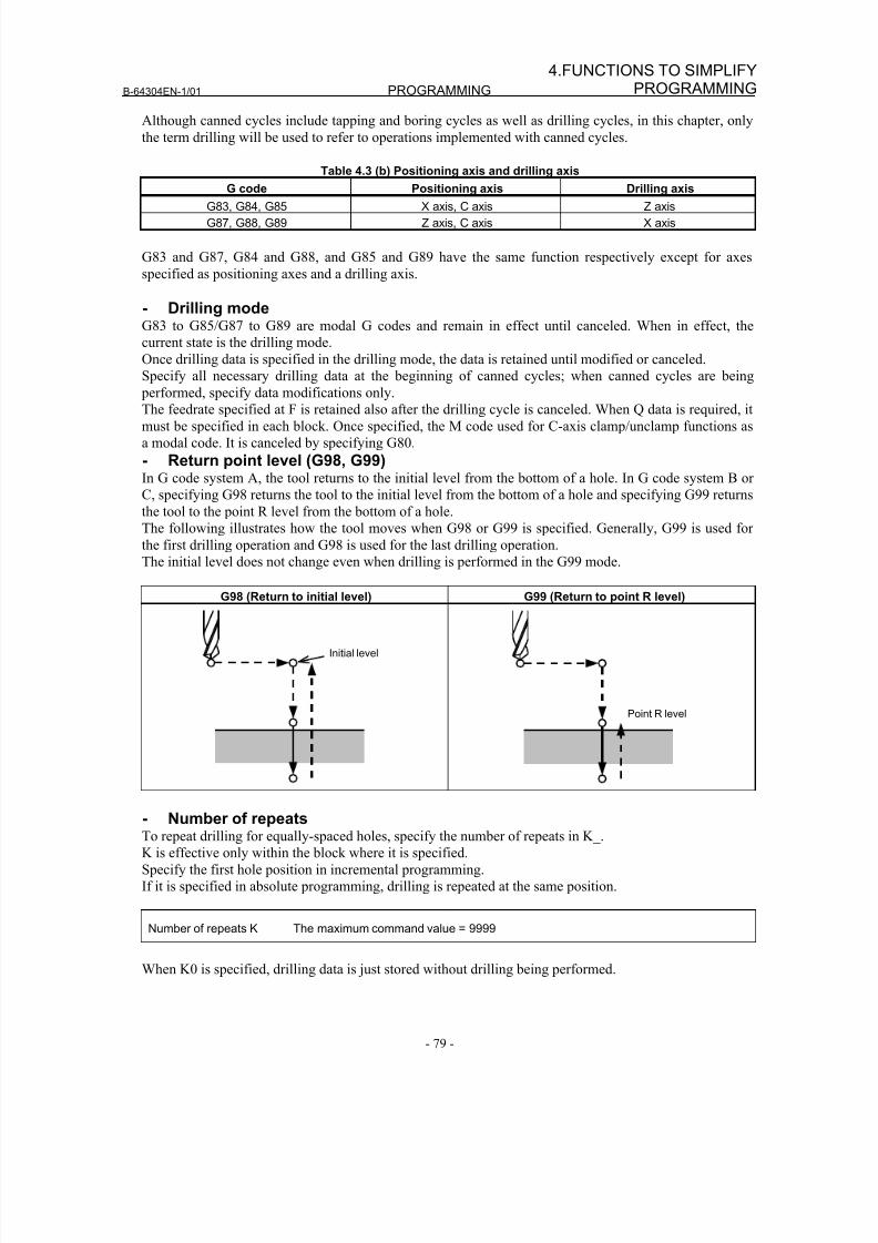
8/16/2019 Manual Operacion para FANUC
http://slidepdf.com/reader/full/manual-operacion-para-fanuc 97/435
B-64304EN-1/01 PROGRAMMING
- 79 -
4.FUNCTIONS TO SIMPLIFYPROGRAMMING
Although canned cycles include tapping and boring cycles as well as drilling cycles, in this chapter, only
the term drilling will be used to refer to operations implemented with canned cycles.
Table 4.3 (b) Positioning axis and drilling axis
G code Positioning axis Drilling axis
G83, G84, G85 X axis, C axis Z axis
G87, G88, G89 Z axis, C axis X axis
G83 and G87, G84 and G88, and G85 and G89 have the same function respectively except for axes
specified as positioning axes and a drilling axis.
- Drilling modeG83 to G85/G87 to G89 are modal G codes and remain in effect until canceled. When in effect, the
current state is the drilling mode.
Once drilling data is specified in the drilling mode, the data is retained until modified or canceled.
Specify all necessary drilling data at the beginning of canned cycles; when canned cycles are being
performed, specify data modifications only.The feedrate specified at F is retained also after the drilling cycle is canceled. When Q data is required, it
must be specified in each block. Once specified, the M code used for C-axis clamp/unclamp functions as
a modal code. It is canceled by specifying G80.
- Return point level (G98, G99)In G code system A, the tool returns to the initial level from the bottom of a hole. In G code system B or
C, specifying G98 returns the tool to the initial level from the bottom of a hole and specifying G99 returns
the tool to the point R level from the bottom of a hole.
The following illustrates how the tool moves when G98 or G99 is specified. Generally, G99 is used for
the first drilling operation and G98 is used for the last drilling operation.
The initial level does not change even when drilling is performed in the G99 mode.
G98 (Return to initial level) G99 (Return to point R level)
Initial level
Point R level
- Number of repeatsTo repeat drilling for equally-spaced holes, specify the number of repeats in K_.
K is effective only within the block where it is specified.
Specify the first hole position in incremental programming.
If it is specified in absolute programming, drilling is repeated at the same position.
Number of repeats K The maximum command value = 9999
When K0 is specified, drilling data is just stored without drilling being performed.
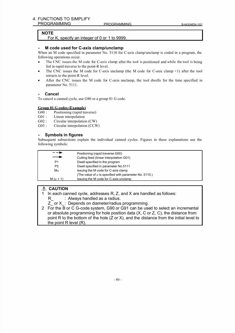
8/16/2019 Manual Operacion para FANUC
http://slidepdf.com/reader/full/manual-operacion-para-fanuc 98/435
PROGRAMMING B-64304EN-1/01
- 80 -
4. FUNCTIONS TO SIMPLIFYPROGRAMMING
NOTEFor K, specify an integer of 0 or 1 to 9999.
- M code used for C-axis clamp/unclamp
When an M code specified in parameter No. 5110 for C-axis clamp/unclamp is coded in a program, thefollowing operations occur.
• The CNC issues the M code for C-axis clamp after the tool is positioned and while the tool is being
fed in rapid traverse to the point-R level.
• The CNC issues the M code for C-axis unclamp (the M code for C-axis clamp +1) after the tool
retracts to the point-R level.
• After the CNC issues the M code for C-axis unclamp, the tool dwells for the time specified in
parameter No. 5111.
- CancelTo cancel a canned cycle, use G80 or a group 01 G code.
Group 01 G codes (Example)
G00 : Positioning (rapid traverse)
G01 : Linear interpolation
G02 : Circular interpolation (CW)
G03 : Circular interpolation (CCW)
- Symbols in figuresSubsequent subsections explain the individual canned cycles. Figures in these explanations use the
following symbols:
Positioning (rapid traverse G00)
Cutting feed (linear interpolation G01)P1 Dwell specified in the program
P2 Dwell specified in parameter No.5111
Mα Issuing the M code for C-axis clamp
(The value of α is specified with parameter No. 5110.)
M (α + 1) Issuing the M code for C-axis unclamp
CAUTION1 In each canned cycle, addresses R, Z, and X are handled as follows:
R_ : Always handled as a radius.Z_ or X_ : Depends on diameter/radius programming.
2 For the B or C G-code system, G90 or G91 can be used to select an incrementalor absolute programming for hole position data (X, C or Z, C), the distance frompoint R to the bottom of the hole (Z or X), and the distance from the initial level tothe point R level (R).
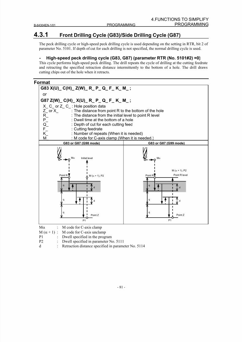
8/16/2019 Manual Operacion para FANUC
http://slidepdf.com/reader/full/manual-operacion-para-fanuc 99/435
B-64304EN-1/01 PROGRAMMING
- 81 -
4.FUNCTIONS TO SIMPLIFYPROGRAMMING
4.3.1 Front Drilling Cycle (G83)/Side Drilling Cycle (G87)
The peck drilling cycle or high-speed peck drilling cycle is used depending on the setting in RTR, bit 2 of
parameter No. 5101. If depth of cut for each drilling is not specified, the normal drilling cycle is used.
- High-speed peck drilling cycle (G83, G87) (parameter RTR (No. 5101#2) =0)This cycle performs high-speed peck drilling. The drill repeats the cycle of drilling at the cutting feedrate
and retracting the specified retraction distance intermittently to the bottom of a hole. The drill draws
cutting chips out of the hole when it retracts.
Format
G83 X(U)_ C(H)_ Z(W)_ R_ P_ Q_ F_ K_ M_ ;
or
G87 Z(W)_ C(H)_ X(U)_ R_ P_ Q_ F_ K_ M_ ;
X_ C_ or Z_ C_ : Hole position dataZ_ or X_ : The distance from point R to the bottom of the holeR_ : The distance from the initial level to point R levelP_ : Dwell time at the bottom of a holeQ_ : Depth of cut for each cutting feedF_ : Cutting feedrateK_ : Number of repeats (When it is needed)M_ : M code for C-axis clamp (When it is needed.)
G83 or G87 (G98 mode) G83 or G87 (G99 mode)
Mα
P1
M (α + 1), P2Point R
q
q
q
d
d
Point Z
Initial level
Point R levelPoint R
q
q
q
d
d
Point Z
P1
M (α + 1), P2
Mα
Mα : M code for C-axis clamp
M (α + 1) : M code for C-axis unclamp
P1 : Dwell specified in the program
P2 : Dwell specified in parameter No. 5111
d : Retraction distance specified in parameter No. 5114
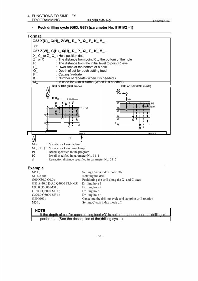
8/16/2019 Manual Operacion para FANUC
http://slidepdf.com/reader/full/manual-operacion-para-fanuc 100/435
PROGRAMMING B-64304EN-1/01
- 82 -
4. FUNCTIONS TO SIMPLIFYPROGRAMMING
- Peck drilling cycle (G83, G87) (parameter No. 5101#2 =1)
Format
G83 X(U)_ C(H)_ Z(W)_ R_ P_ Q_ F_ K_ M_ ;
or
G87 Z(W)_ C(H)_ X(U)_ R_ P_ Q_ F_ K_ M_ ;
X_ C_ or Z_ C_ : Hole position dataZ_ or X_ : The distance from point R to the bottom of the holeR_ : The distance from the initial level to point R levelP_ : Dwell time at the bottom of a holeQ_ : Depth of cut for each cutting feedF_ : Cutting feedrateK_ : Number of repeats (When it is needed.)M_ : M code for C-axis clamp (When it is needed.)
G83 or G87 (G98 mode) G83 or G87 (G99 mode)
Point R
q
q
q
d
Point Z
Initial level
d
Mα
P1
M (α + 1), P2
Point R
q
q
q
d
Point Z
Point R level
d
Mα
M (α + 1), P2
P1
Mα : M code for C-axis clamp
M (α + 1) : M code for C-axis unclamp
P1 : Dwell specified in the program
P2 : Dwell specified in parameter No. 5111
d : Retraction distance specified in parameter No. 5115
ExampleM51 ; Setting C-axis index mode ON
M3 S2000 ; Rotating the drillG00 X50.0 C0.0 ; Positioning the drill along the X- and C-axes
G83 Z-40.0 R-5.0 Q5000 F5.0 M31 ; Drilling hole 1
C90.0 Q5000 M31 ; Drilling hole 2
C180.0 Q5000 M31 ; Drilling hole 3
C270.0 Q5000 M31 ; Drilling hole 4
G80 M05 ; Canceling the drilling cycle and stopping drill rotation
M50 ; Setting C-axis index mode off
NOTEIf the depth of cut for each cutting feed (Q) is not commanded, normal drilling isperformed. (See the description of the drilling cycle.)
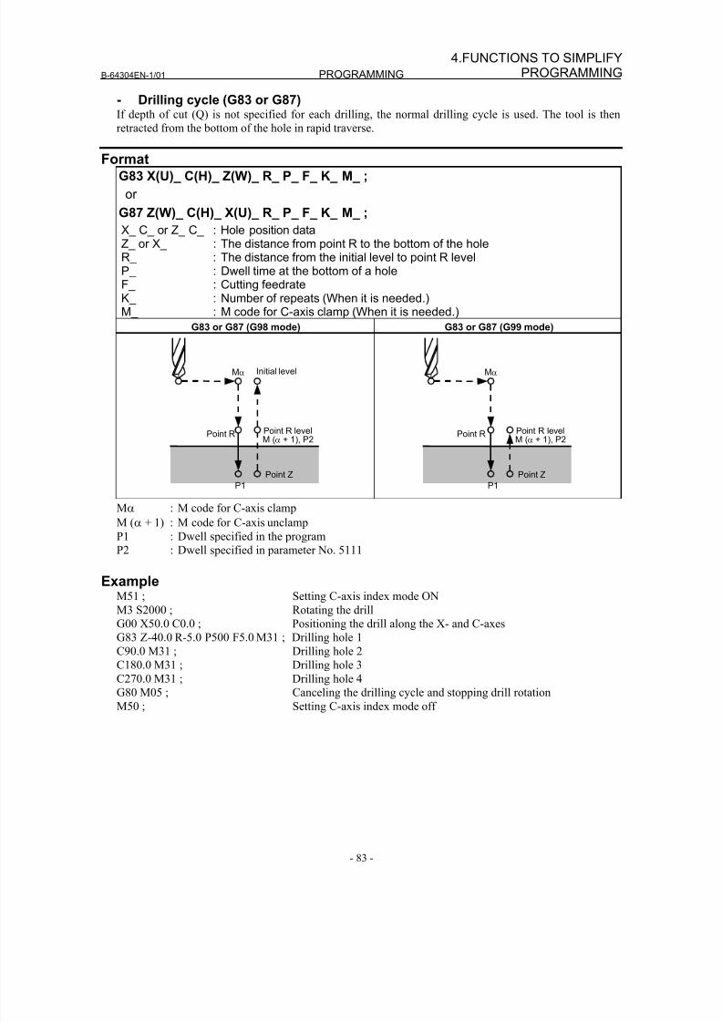
8/16/2019 Manual Operacion para FANUC
http://slidepdf.com/reader/full/manual-operacion-para-fanuc 101/435
B-64304EN-1/01 PROGRAMMING
- 83 -
4.FUNCTIONS TO SIMPLIFYPROGRAMMING
- Drilling cycle (G83 or G87)If depth of cut (Q) is not specified for each drilling, the normal drilling cycle is used. The tool is then
retracted from the bottom of the hole in rapid traverse.
FormatG83 X(U)_ C(H)_ Z(W)_ R_ P_ F_ K_ M_ ;
or
G87 Z(W)_ C(H)_ X(U)_ R_ P_ F_ K_ M_ ;
X_ C_ or Z_ C_ : Hole position dataZ_ or X_ : The distance from point R to the bottom of the holeR_ : The distance from the initial level to point R levelP_ : Dwell time at the bottom of a holeF_ : Cutting feedrateK_ : Number of repeats (When it is needed.)M_ : M code for C-axis clamp (When it is needed.)
G83 or G87 (G98 mode) G83 or G87 (G99 mode)
Initial level
Point R
Point Z
Point R levelM (α + 1), P2
Mα
P1
Point R levelPoint R
Point Z
M (α + 1), P2
P1
Mα
Mα : M code for C-axis clamp
M (α + 1) : M code for C-axis unclamp
P1 : Dwell specified in the program
P2 : Dwell specified in parameter No. 5111
ExampleM51 ; Setting C-axis index mode ON
M3 S2000 ; Rotating the drill
G00 X50.0 C0.0 ; Positioning the drill along the X- and C-axes
G83 Z-40.0 R-5.0 P500 F5.0 M31 ; Drilling hole 1C90.0 M31 ; Drilling hole 2
C180.0 M31 ; Drilling hole 3
C270.0 M31 ; Drilling hole 4
G80 M05 ; Canceling the drilling cycle and stopping drill rotation
M50 ; Setting C-axis index mode off
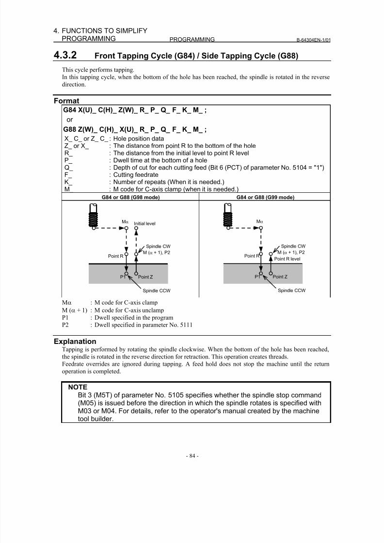
8/16/2019 Manual Operacion para FANUC
http://slidepdf.com/reader/full/manual-operacion-para-fanuc 102/435
PROGRAMMING B-64304EN-1/01
- 84 -
4. FUNCTIONS TO SIMPLIFYPROGRAMMING
4.3.2 Front Tapping Cycle (G84) / Side Tapping Cycle (G88)
This cycle performs tapping.
In this tapping cycle, when the bottom of the hole has been reached, the spindle is rotated in the reverse
direction.
Format
G84 X(U)_ C(H)_ Z(W)_ R_ P_ Q_ F_ K_ M_ ;
or
G88 Z(W)_ C(H)_ X(U)_ R_ P_ Q_ F_ K_ M_ ;
X_ C_ or Z_ C_ : Hole position dataZ_ or X_ : The distance from point R to the bottom of the holeR_ : The distance from the initial level to point R levelP_ : Dwell time at the bottom of a hole
Q_ : Depth of cut for each cutting feed (Bit 6 (PCT) of parameter No. 5104 = "1")F_ : Cutting feedrateK_ : Number of repeats (When it is needed.)M_ : M code for C-axis clamp (when it is needed.)
G84 or G88 (G98 mode) G84 or G88 (G99 mode)
Point R
Point Z
Spindle CCW
Spindle CW
Initial level
M (α + 1), P2
Mα
P1
Point R
Point Z
Spindle CCW
Spindle CW
Point R level
P1
Mα
M (α + 1), P2
Mα : M code for C-axis clamp
M (α + 1) : M code for C-axis unclamp
P1 : Dwell specified in the program
P2 : Dwell specified in parameter No. 5111
ExplanationTapping is performed by rotating the spindle clockwise. When the bottom of the hole has been reached,
the spindle is rotated in the reverse direction for retraction. This operation creates threads.
Feedrate overrides are ignored during tapping. A feed hold does not stop the machine until the return
operation is completed.
NOTEBit 3 (M5T) of parameter No. 5105 specifies whether the spindle stop command(M05) is issued before the direction in which the spindle rotates is specified withM03 or M04. For details, refer to the operator's manual created by the machinetool builder.
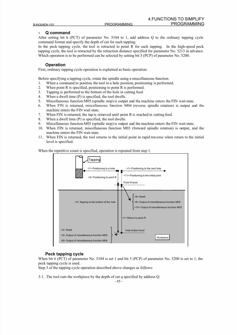
8/16/2019 Manual Operacion para FANUC
http://slidepdf.com/reader/full/manual-operacion-para-fanuc 103/435
B-64304EN-1/01 PROGRAMMING
- 85 -
4.FUNCTIONS TO SIMPLIFYPROGRAMMING
- Q commandAfter setting bit 6 (PCT) of parameter No. 5104 to 1, add address Q to the ordinary tapping cycle
command format and specify the depth of cut for each tapping.
In the peck tapping cycle, the tool is retracted to point R for each tapping. In the high-speed peck
tapping cycle, the tool is retracted by the retraction distance specified for parameter No. 5213 in advance.Which operation is to be performed can be selected by setting bit 5 (PCP) of parameter No. 5200.
OperationFirst, ordinary tapping cycle operation is explained as basic operation.
Before specifying a tapping cycle, rotate the spindle using a miscellaneous function.
1. When a command to position the tool to a hole position, positioning is performed.
2. When point R is specified, positioning to point R is performed.
3. Tapping is performed to the bottom of the hole in cutting feed.
4. When a dwell time (P) is specified, the tool dwells.
5. Miscellaneous function M05 (spindle stop) is output and the machine enters the FIN wait state.
6. When FIN is returned, miscellaneous function M04 (reverse spindle rotation) is output and themachine enters the FIN wait state.
7. When FIN is returned, the tap is removed until point R is reached in cutting feed.
8. When a dwell time (P) is specified, the tool dwells.
9. Miscellaneous function M05 (spindle stop) is output and the machine enters the FIN wait state.
10. When FIN is returned, miscellaneous function M03 (forward spindle rotation) is output, and the
machine enters the FIN wait state.
11. When FIN is returned, the tool returns to the initial point in rapid traverse when return to the initial
level is specified.
When the repetitive count is specified, operation is repeated from step 1.
<1> Positioning to a hole
<2> Positioning to point R
Point R level
Hole bottom level
<3> Tapping to the bottom of the hole
<4> Dwell
<5> Output of miscellaneous function M05
<6> Output of miscellaneous function M04
<7> Return to point R
<8> Dwell
<9> Output of miscellaneous function M05
<10> Output of miscellaneous function M03
<11> Positioning to the initial point
<1> Positioning to the next hole
Workpiece
Tapping
Peck tapping cycleWhen bit 6 (PCT) of parameter No. 5104 is set 1 and bit 5 (PCP) of parameter No. 5200 is set to 1, the
peck tapping cycle is used.Step 3 of the tapping cycle operation described above changes as follows:
3-1. The tool cuts the workpiece by the depth of cut q specified by address Q.
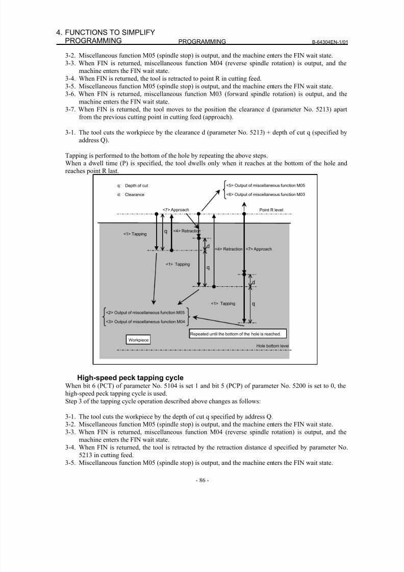
8/16/2019 Manual Operacion para FANUC
http://slidepdf.com/reader/full/manual-operacion-para-fanuc 104/435
PROGRAMMING B-64304EN-1/01
- 86 -
4. FUNCTIONS TO SIMPLIFYPROGRAMMING
3-2. Miscellaneous function M05 (spindle stop) is output, and the machine enters the FIN wait state.
3-3. When FIN is returned, miscellaneous function M04 (reverse spindle rotation) is output, and the
machine enters the FIN wait state.
3-4. When FIN is returned, the tool is retracted to point R in cutting feed.
3-5. Miscellaneous function M05 (spindle stop) is output, and the machine enters the FIN wait state.
3-6. When FIN is returned, miscellaneous function M03 (forward spindle rotation) is output, and the
machine enters the FIN wait state.
3-7. When FIN is returned, the tool moves to the position the clearance d (parameter No. 5213) apart
from the previous cutting point in cutting feed (approach).
3-1. The tool cuts the workpiece by the clearance d (parameter No. 5213) + depth of cut q (specified by
address Q).
Tapping is performed to the bottom of the hole by repeating the above steps.
When a dwell time (P) is specified, the tool dwells only when it reaches at the bottom of the hole and
reaches point R last.
Point R level
Hole bottom level Workpiece
q
d
q
q
<2> Output of miscellaneous function M05
<3> Output of miscellaneous function M04
<5> Output of miscellaneous function M05
<6> Output of miscellaneous function M03
<1> Tapping
<1> Tapping
<1> Tapping
<4> Retraction
<4> Retraction
d
<7> Approach
Repeated until the bottom of the hole is reached.
q: Depth of cut
d: Clearance
<7> Approach
High-speed peck tapping cycleWhen bit 6 (PCT) of parameter No. 5104 is set 1 and bit 5 (PCP) of parameter No. 5200 is set to 0, the
high-speed peck tapping cycle is used.
Step 3 of the tapping cycle operation described above changes as follows:
3-1. The tool cuts the workpiece by the depth of cut q specified by address Q.
3-2. Miscellaneous function M05 (spindle stop) is output, and the machine enters the FIN wait state.
3-3. When FIN is returned, miscellaneous function M04 (reverse spindle rotation) is output, and the
machine enters the FIN wait state.
3-4. When FIN is returned, the tool is retracted by the retraction distance d specified by parameter No.5213 in cutting feed.
3-5. Miscellaneous function M05 (spindle stop) is output, and the machine enters the FIN wait state.
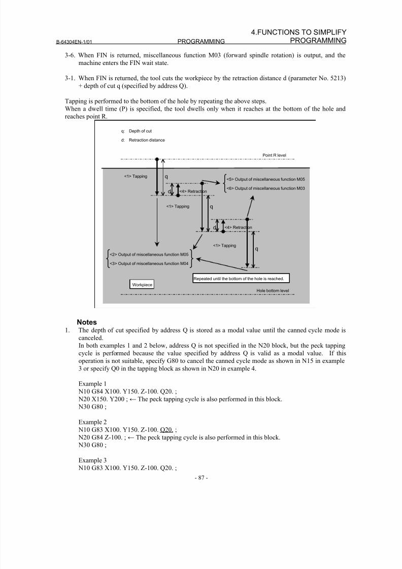
8/16/2019 Manual Operacion para FANUC
http://slidepdf.com/reader/full/manual-operacion-para-fanuc 105/435
B-64304EN-1/01 PROGRAMMING
- 87 -
4.FUNCTIONS TO SIMPLIFYPROGRAMMING
3-6. When FIN is returned, miscellaneous function M03 (forward spindle rotation) is output, and the
machine enters the FIN wait state.
3-1. When FIN is returned, the tool cuts the workpiece by the retraction distance d (parameter No. 5213)
+ depth of cut q (specified by address Q).
Tapping is performed to the bottom of the hole by repeating the above steps.
When a dwell time (P) is specified, the tool dwells only when it reaches at the bottom of the hole and
reaches point R.
Point R level
Hole bottom level Workpiece
q
d
q
d
q<2> Output of miscellaneous function M05
<3> Output of miscellaneous function M04
<5> Output of miscellaneous function M05
<6> Output of miscellaneous function M03
<1> Tapping
<1> Tapping
<1> Tapping
<4> Retraction
<4> Retraction
Repeated until the bottom of the hole is reached.
q: Depth of cut
d: Retraction distance
Notes1. The depth of cut specified by address Q is stored as a modal value until the canned cycle mode is
canceled.
In both examples 1 and 2 below, address Q is not specified in the N20 block, but the peck tapping
cycle is performed because the value specified by address Q is valid as a modal value. If this
operation is not suitable, specify G80 to cancel the canned cycle mode as shown in N15 in example
3 or specify Q0 in the tapping block as shown in N20 in example 4.
Example 1
N10 G84 X100. Y150. Z-100. Q20. ;
N20 X150. Y200 ;← The peck tapping cycle is also performed in this block.
N30 G80 ;
Example 2
N10 G83 X100. Y150. Z-100. Q20. ;
N20 G84 Z-100. ;← The peck tapping cycle is also performed in this block.
N30 G80 ;
Example 3
N10 G83 X100. Y150. Z-100. Q20. ;
8/16/2019 Manual Operacion para FANUC
http://slidepdf.com/reader/full/manual-operacion-para-fanuc 106/435
PROGRAMMING B-64304EN-1/01
- 88 -
4. FUNCTIONS TO SIMPLIFYPROGRAMMING
N15 G80 ;← The canned cycle mode is canceled.
N20 G84 Z-100. ;
N30 G80 ;
Example 4
N10 G83 X100. Y150. Z-100. Q20. ;
N20 G84 Z-100. Q0 ;←Q0 is added.
N30 G80 ;
2. The unit for the reference axis that is set by parameter No. 1031, not the unit for the drilling axis is
used as the unit of Q. Any sign is ignored.
3. Specify a radius value at address Q even when a diameter axis is used.
4. Perform operation in the peck tapping cycle within point R. That is, set a value which does not
exceed point R for d (parameter No. 5213).
ExampleM51 ; Setting C-axis index mode ON
M3 S2000 ; Rotating the drill
G00 X50.0 C0.0 ; Positioning the drill along the X- and C- axes
G84 Z-40.0 R-5.0 P500 F5.0 M31 ; Drilling hole 1
C90.0 M31 ; Drilling hole 2
C180.0 M31 ; Drilling hole 3
C270.0 M31 ; Drilling hole 4
G80 M05 ; Canceling the drilling cycle and stopping drill rotation
M50 ; Setting C-axis index mode off
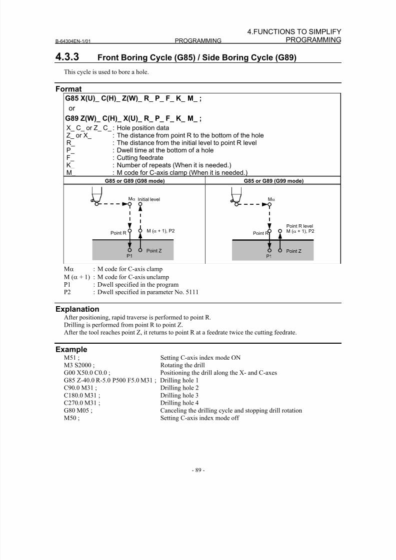
8/16/2019 Manual Operacion para FANUC
http://slidepdf.com/reader/full/manual-operacion-para-fanuc 107/435
B-64304EN-1/01 PROGRAMMING
- 89 -
4.FUNCTIONS TO SIMPLIFYPROGRAMMING
4.3.3 Front Boring Cycle (G85) / Side Boring Cycle (G89)
This cycle is used to bore a hole.
FormatG85 X(U)_ C(H)_ Z(W)_ R_ P_ F_ K_ M_ ;
or
G89 Z(W)_ C(H)_ X(U)_ R_ P_ F_ K_ M_ ;
X_ C_ or Z_ C_ : Hole position dataZ_ or X_ : The distance from point R to the bottom of the holeR_ : The distance from the initial level to point R levelP_ : Dwell time at the bottom of a holeF_ : Cutting feedrateK_ : Number of repeats (When it is needed.)
M_ : M code for C-axis clamp (When it is needed.)G85 or G89 (G98 mode) G85 or G89 (G99 mode)
Point R
Point Z
Initial level
M (α + 1), P2
Mα
P1
Point R
Point Z
Point R level
Mα
P1
M (α + 1), P2
Mα : M code for C-axis clamp
M (α + 1) : M code for C-axis unclamp
P1 : Dwell specified in the program
P2 : Dwell specified in parameter No. 5111
ExplanationAfter positioning, rapid traverse is performed to point R.
Drilling is performed from point R to point Z.
After the tool reaches point Z, it returns to point R at a feedrate twice the cutting feedrate.
ExampleM51 ; Setting C-axis index mode ON
M3 S2000 ; Rotating the drill
G00 X50.0 C0.0 ; Positioning the drill along the X- and C-axes
G85 Z-40.0 R-5.0 P500 F5.0 M31 ; Drilling hole 1
C90.0 M31 ; Drilling hole 2
C180.0 M31 ; Drilling hole 3
C270.0 M31 ; Drilling hole 4
G80 M05 ; Canceling the drilling cycle and stopping drill rotation
M50 ; Setting C-axis index mode off
8/16/2019 Manual Operacion para FANUC
http://slidepdf.com/reader/full/manual-operacion-para-fanuc 108/435
PROGRAMMING B-64304EN-1/01
- 90 -
4. FUNCTIONS TO SIMPLIFYPROGRAMMING
4.3.4 Canned Cycle for Drilling Cancel (G80)
G80 cancels canned cycle for drilling.
Format
G80 ;
ExplanationCanned cycle for drilling is canceled to perform normal operation. Point R and point Z are cleared.
Other drilling data is also canceled (cleared).
ExampleM51 ; Setting C-axis index mode ON
M3 S2000 ; Rotating the drill
G00 X50.0 C0.0 ; Positioning the drill along the X- and C-axes.G83 Z-40.0 R-5.0 P500 F5.0 M31 ; Drilling hole 1
C90.0 M31 ; Drilling hole 2
C180.0 M31 ; Drilling hole 3
C270.0 M31 ; Drilling hole 4
G80 M05 ; Canceling the drilling cycle and stopping drill rotation
M50 ; Setting C-axis index mode off
4.3.5 Precautions to be Taken by Operator
- Reset and emergency stop
Even when the controller is stopped by resetting or emergency stop in the course of drilling cycle, thedrilling mode and drilling data are saved; with this mind, therefore, restart operation.
- Single blockWhen drilling cycle is performed with a single block, the operation stops at the end points of operations 1,
2, 6 in Fig. 4.3 (a).
Consequently, it follows that operation is started up 3 times to drill one hole. The operation stops at the
end points of operations 1, 2 with the feed hold lamp ON. If there is a remaining repetitive count at the
end of operation 6, the operation is stopped by feed hold. If there is no remaining repetitive count, the
operation is stopped in the single block stop state.
- Feed holdWhen "Feed Hold" is applied between operations 3 and 5 by G84/G88, the feed hold lamp lights up
immediately if the feed hold is applied again to operation 6.
- OverrideDuring operation with G84 and G88, the feedrate override is 100%.
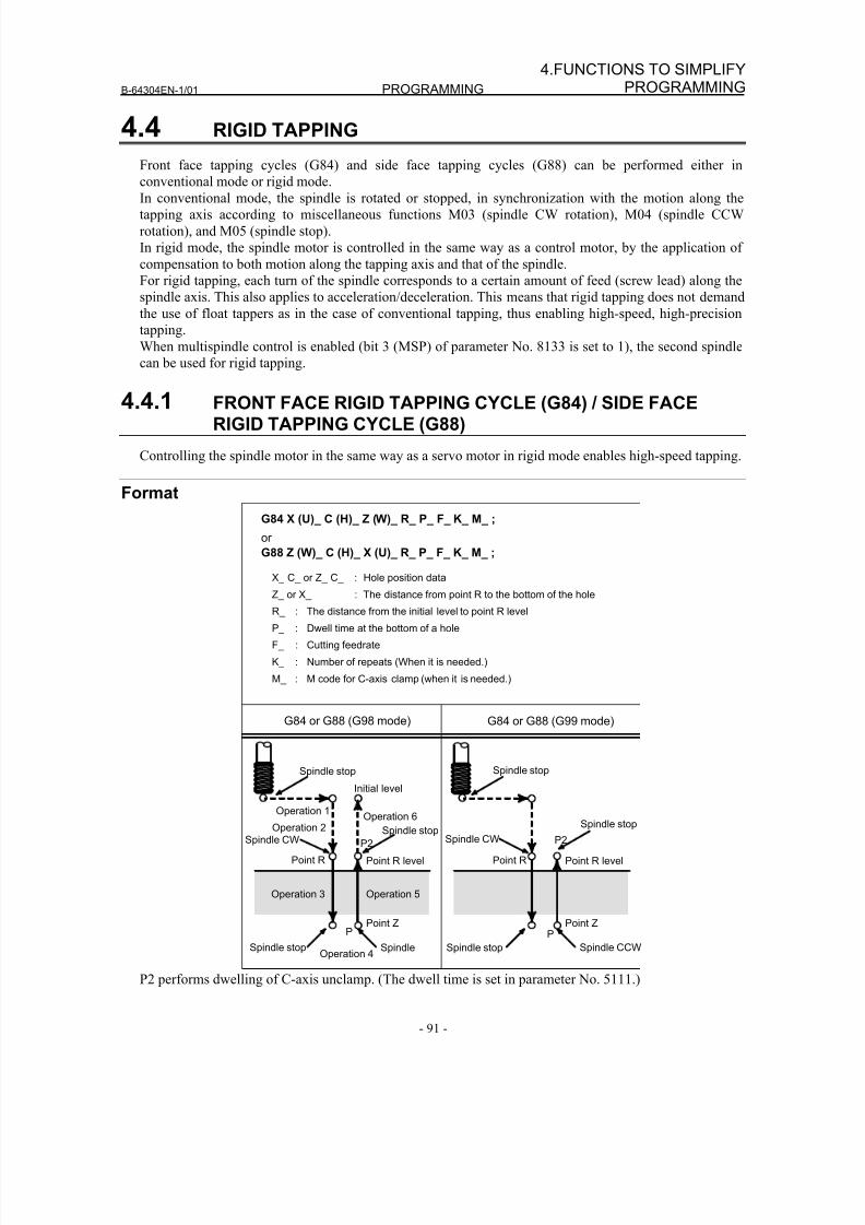
8/16/2019 Manual Operacion para FANUC
http://slidepdf.com/reader/full/manual-operacion-para-fanuc 109/435
B-64304EN-1/01 PROGRAMMING
- 91 -
4.FUNCTIONS TO SIMPLIFYPROGRAMMING
4.4 RIGID TAPPING
Front face tapping cycles (G84) and side face tapping cycles (G88) can be performed either in
conventional mode or rigid mode.
In conventional mode, the spindle is rotated or stopped, in synchronization with the motion along the
tapping axis according to miscellaneous functions M03 (spindle CW rotation), M04 (spindle CCW
rotation), and M05 (spindle stop).
In rigid mode, the spindle motor is controlled in the same way as a control motor, by the application of
compensation to both motion along the tapping axis and that of the spindle.
For rigid tapping, each turn of the spindle corresponds to a certain amount of feed (screw lead) along the
spindle axis. This also applies to acceleration/deceleration. This means that rigid tapping does not demand
the use of float tappers as in the case of conventional tapping, thus enabling high-speed, high-precision
tapping.
When multispindle control is enabled (bit 3 (MSP) of parameter No. 8133 is set to 1), the second spindle
can be used for rigid tapping.
4.4.1 FRONT FACE RIGID TAPPING CYCLE (G84) / SIDE FACERIGID TAPPING CYCLE (G88)
Controlling the spindle motor in the same way as a servo motor in rigid mode enables high-speed tapping.
Format
G84 X (U)_ C (H)_ Z (W)_ R_ P_ F_ K_ M_ ;
or
G88 Z (W)_ C (H)_ X (U)_ R_ P_ F_ K_ M_ ;
X_ C_ or Z_ C_ : Hole position data
Z_ or X_ : The distance from point R to the bottom of the hole
R_ : The distance from the initial level to point R level
P_ : Dwell time at the bottom of a hole
F_ : Cutting feedrate
K_ : Number of repeats (When it is needed.)
M_ : M code for C-axis clamp (when it is needed.)
G84 or G88 (G98 mode) G84 or G88 (G99 mode)
Initial level
Point R
Spindle stopSpindle CW
Point ZP
Point R level
Operation 2
Operation 1Operation 6
Operation 3
Operation 4
Operation 5
Spindle stop Spindle
Point R
Point ZP
Point R level
Spindle stop Spindle CCW
Spindle stop Spindle stop
Spindle stop
P2 P2Spindle CW
P2 performs dwelling of C-axis unclamp. (The dwell time is set in parameter No. 5111.)
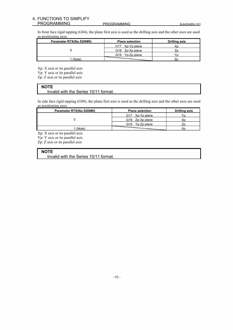
8/16/2019 Manual Operacion para FANUC
http://slidepdf.com/reader/full/manual-operacion-para-fanuc 110/435
PROGRAMMING B-64304EN-1/01
- 92 -
4. FUNCTIONS TO SIMPLIFYPROGRAMMING
In front face rigid tapping (G84), the plane first axis is used as the drilling axis and the other axes are used
as positioning axes.
Parameter RTX(No.5209#0) Plane selection Drilling axis
G17 Xp-Yp plane Xp
G18 Zp-Xp plane Zp0G19 Yp-Zp plane Yp
1 (Note) Zp
Xp: X axis or its parallel axis
Yp: Y axis or its parallel axis
Zp: Z axis or its parallel axis
NOTEInvalid with the Series 10/11 format.
In side face rigid tapping (G88), the plane first axis is used as the drilling axis and the other axes are used
as positioning axes.
Parameter RTX(No.5209#0) Plane selection Drilling axis
G17 Xp-Yp plane Yp
G18 Zp-Xp plane Xp0
G19 Yp-Zp plane Zp
1 (Note) Xp
Xp: X axis or its parallel axis
Yp: Y axis or its parallel axis
Zp: Z axis or its parallel axis
NOTE
Invalid with the Series 10/11 format.
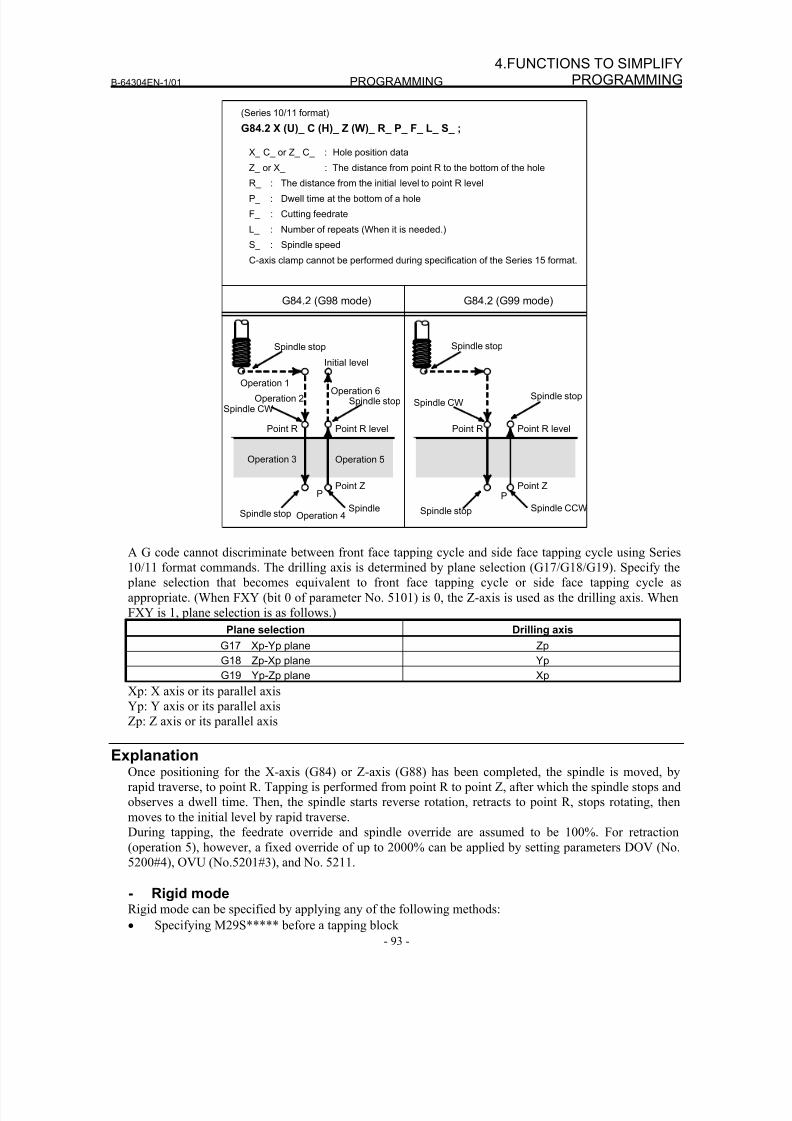
8/16/2019 Manual Operacion para FANUC
http://slidepdf.com/reader/full/manual-operacion-para-fanuc 111/435
B-64304EN-1/01 PROGRAMMING
- 93 -
4.FUNCTIONS TO SIMPLIFYPROGRAMMING
(Series 10/11 format)
G84.2 X (U)_ C (H)_ Z (W)_ R_ P_ F_ L_ S_ ;
X_ C_ or Z_ C_ : Hole position data
Z_ or X_ : The distance from point R to the bottom of the hole
R_ : The distance from the initial level to point R level
P_ : Dwell time at the bottom of a hole
F_ : Cutting feedrate
L_ : Number of repeats (When it is needed.)
S_ : Spindle speed
C-axis clamp cannot be performed during specification of the Series 15 format.
G84.2 (G98 mode) G84.2 (G99 mode)
Initial level
Point R
Spindle stopSpindle CW
Point ZP
Point R level
Operation 2
Operation 1Operation 6
Operation 3
Operation 4
Operation 5
Spindle stopSpindle
Point R
Spindle CW
Point ZP
Point R level
Spindle stop Spindle CCW
Spindle stop Spindle stop
Spindle stop
A G code cannot discriminate between front face tapping cycle and side face tapping cycle using Series
10/11 format commands. The drilling axis is determined by plane selection (G17/G18/G19). Specify the
plane selection that becomes equivalent to front face tapping cycle or side face tapping cycle as
appropriate. (When FXY (bit 0 of parameter No. 5101) is 0, the Z-axis is used as the drilling axis. When
FXY is 1, plane selection is as follows.)
Plane selection Drilling axis
G17 Xp-Yp plane Zp
G18 Zp-Xp plane Yp
G19 Yp-Zp plane Xp
Xp: X axis or its parallel axis
Yp: Y axis or its parallel axisZp: Z axis or its parallel axis
ExplanationOnce positioning for the X-axis (G84) or Z-axis (G88) has been completed, the spindle is moved, by
rapid traverse, to point R. Tapping is performed from point R to point Z, after which the spindle stops and
observes a dwell time. Then, the spindle starts reverse rotation, retracts to point R, stops rotating, then
moves to the initial level by rapid traverse.
During tapping, the feedrate override and spindle override are assumed to be 100%. For retraction
(operation 5), however, a fixed override of up to 2000% can be applied by setting parameters DOV (No.
5200#4), OVU (No.5201#3), and No. 5211.
- Rigid modeRigid mode can be specified by applying any of the following methods:
• Specifying M29S***** before a tapping block
8/16/2019 Manual Operacion para FANUC
http://slidepdf.com/reader/full/manual-operacion-para-fanuc 112/435
PROGRAMMING B-64304EN-1/01
- 94 -
4. FUNCTIONS TO SIMPLIFYPROGRAMMING
• Specifying M29S***** within a tapping block
• Handling G84 or G88 as a G code for rigid tapping (Set parameter G84 (No. 5200#0) to 1.)
- Thread lead
In feed per minute mode, the feedrate divided by the spindle speed is equal to the thread lead. In feed perrotation mode, the feedrate is equal to the thread lead.
- Series 10/11 format commandWhen bit 1 (FCV) of parameter No. 0001 is set to 1, rigid tapping can be executed with G84.2. The
same operation as with G84 is performed. The command format for the repetitive count is L, however.
- Acceleration/deceleration after interpolationLinear or bell-shaped acceleration/deceleration can be applied.
Details are given later.
- Look-ahead acceleration/deceleration before interpolationLook-ahead acceleration/deceleration before interpolation is invalid.
- OverrideVarious types of override functions are invalid. The following override functions can be enabled by
setting corresponding parameters:
• Extraction override
• Override signal
- Dry runDry run can be executed also in G84 (G88). When dry run is executed at the feedrate for the drilling axis
in G84 (G88), tapping is performed according to the feedrate. Note that the spindle speed becomes faster
at a higher dry run feedrate.
- Machine lockMachine lock can be executed also in G84 (G88).
When G84 (G88) is executed in the machine lock state, the tool does not move along the drilling axis.
Therefore, the spindle does not also rotate.
- ResetWhen a reset is performed during rigid tapping, the rigid tapping mode is canceled and the spindle motor
enters the normal mode. Note that the G84 (G88) mode is not canceled in this case when bit 6 (CLR) of
parameter No. 3402 is set.
- InterlockInterlock can also be applied in G84 (G88).
- Feed hold and single blockWhen parameter FHD (No. 5200#6) is set to 0, feed hold and single block are invalid in the G84 (G88)
mode. When this bit is set to 1, they are valid.
- Manual feedFor rigid tapping by manual handle feed, see the section "Rigid Tapping by Manual Handle."
With other manual operations, rigid tapping cannot be performed.
8/16/2019 Manual Operacion para FANUC
http://slidepdf.com/reader/full/manual-operacion-para-fanuc 113/435
B-64304EN-1/01 PROGRAMMING
- 95 -
4.FUNCTIONS TO SIMPLIFYPROGRAMMING
- Backlash compensationIn the rigid tapping mode, backlash compensation is applied to compensate the lost motion when the
spindle rotates clockwise or counterclockwise. Set the amount of backlash in parameters Nos. 5321 to
5324.
Along the drilling axis, backlash compensation has been applied.
- C-axis clamp, C-axis unclampIt is possible to specify an M code for mechanically fixing or releasing the C-axis during rigid tapping.
Adding an M code for clamp to the G84 (G88) block outputs both M codes. Descriptions of timing are
provided later.
An M code for clamp is set in parameter No. 5110. An M code for unclamp is assumed as follows
depending on the setting of parameter No. 5110.
Parameter No.5110
0 Non-0
No M codes are output. The setting of parameter No.5110 + 1 is assumed.
Limitation- Axis switchingBefore the drilling axis can be changed, the canned cycle must be canceled. If the drilling axis is changed
in rigid mode, alarm PS0206 is issued.
- S commandsWhen a value exceeding the maximum rotation speed for the gear being used is specified, alarm PS0200
is issued. If such a command that the number of pulses of 8 msec is 32768 or more on the detection unit
level or the number of pulses of 8 msec is 32768 or more for a serial spindle is specified, alarm PS0202 is
issued.
<Example>For a built-in motor equipped with a detector having a resolution of 4095 pulses per rotation, the
maximum spindle speed during rigid tapping is as follows (in the case of 8 msec):
(4095×1000÷8×60)÷4095=7500 (min-1
)
For a serial spindle
(32767×1000÷8×60)÷4095=60012(min-1) [Note:Ideal value]
When rigid tapping is canceled, the S value used for rigid tapping is cleared (as if S0 is specified).
- F commandsSpecifying a value larger than the upper limit for cutting feed will cause alarm PS0201 to be issued.
- Unit of F commandMetric input Inch input Remarks
G98 1mm/min 0.01inch/min Decimal point programming allowed
G99 0.01mm/rev 0.0001inch/rev Decimal point programming allowed
- M29If an S command and axis movement are specified between M29 and G84, alarm PS0203 is issued. If
M29 is specified in a tapping cycle, alarm PS0204 is issued.
- Rigid tapping command M codeThe M code used to specify the rigid tapping mode is set in parameter No. 5210.
- PSpecify P in a block that performs drilling. If P is specified in a non-drilling block, it is not stored as
modal data.
8/16/2019 Manual Operacion para FANUC
http://slidepdf.com/reader/full/manual-operacion-para-fanuc 114/435
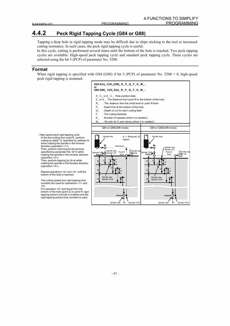
8/16/2019 Manual Operacion para FANUC
http://slidepdf.com/reader/full/manual-operacion-para-fanuc 115/435
B-64304EN-1/01 PROGRAMMING
- 97 -
4.FUNCTIONS TO SIMPLIFYPROGRAMMING
4.4.2 Peck Rigid Tapping Cycle (G84 or G88)
Tapping a deep hole in rigid tapping mode may be difficult due to chips sticking to the tool or increased
cutting resistance. In such cases, the peck rigid tapping cycle is useful.
In this cycle, cutting is performed several times until the bottom of the hole is reached. Two peck tappingcycles are available: High-speed peck tapping cycle and standard peck tapping cycle. These cycles are
selected using the bit 5 (PCP) of parameter No. 5200.
FormatWhen rigid tapping is specified with G84 (G88) if bit 5 (PCP) of parameter No. 5200 = 0, high-speed
peck rigid tapping is assumed.
Point R
level
Point Z
Point R
q
q
q
M
(1)d
(2)
d
Spindle CCW
Spindle stop
M( +1)P2
Spindle stopSpindle CCW
Spindle stopSpindle CW
Spindle CW
P1Spindle stop
(3)
Spindle stop
G84 or G88(G98 mode) G84 or G88(G99 mode)
G84 X(U)_ C(H)_Z(W)_ R_ P_ Q_ F_ K_ M_ ;orG88 Z(W)_ C(H)_X(U)_ R_ P_ Q_ F_ K_ M_ ;
X_ C_ or Z_ C_ : Hole position data
Z_ or X_ : The distance from point R to the bottom of the hole
R_ : The distance from the initial level to point R level
P_ : Dwell time at the bottom of the hole
Q_ : Depth of cut for each cutting feed
F_ : The cutting feedrate
K_ : Number of repeats (when it is needed.)
M_ : M code for C-axis clamp (when it is needed.)
- High-speed peck rigid tapping cycleIn the first cutting from point R, performcutting by depth "q" specified by address Qwhile rotating the spindle in the forwarddirection (operation <1>).Then, perform returning by the amountspecified by parameter No. 5213 whilerotating the spindle in the reverse direction(operation <2>).Then, perform tapping by (d+q) whilerotating the spindle in the forward direction(operation <3>).
Repeat operations <2> and <3> until thebottom of the hole is reached.
The cutting speed and rigid tapping timeconstant are used for operations <1> and<3>.For operation <2> and travel from thebottom of the hole (point Z) to point R, rigidtapping extract override is enabled and therigid tapping extract time constant is used.
d = Amount of return
Spindle stop
(3)
Point R
level
P1Spindle stop
Spindle CWPoint R
Point Z
q
q
q
M
(1)d
(2)
d
Initial level
Spindle CCW
Spindle stop
M( +1)P2
Spindle stopSpindle CCW
Spindle stop
Spindle CW
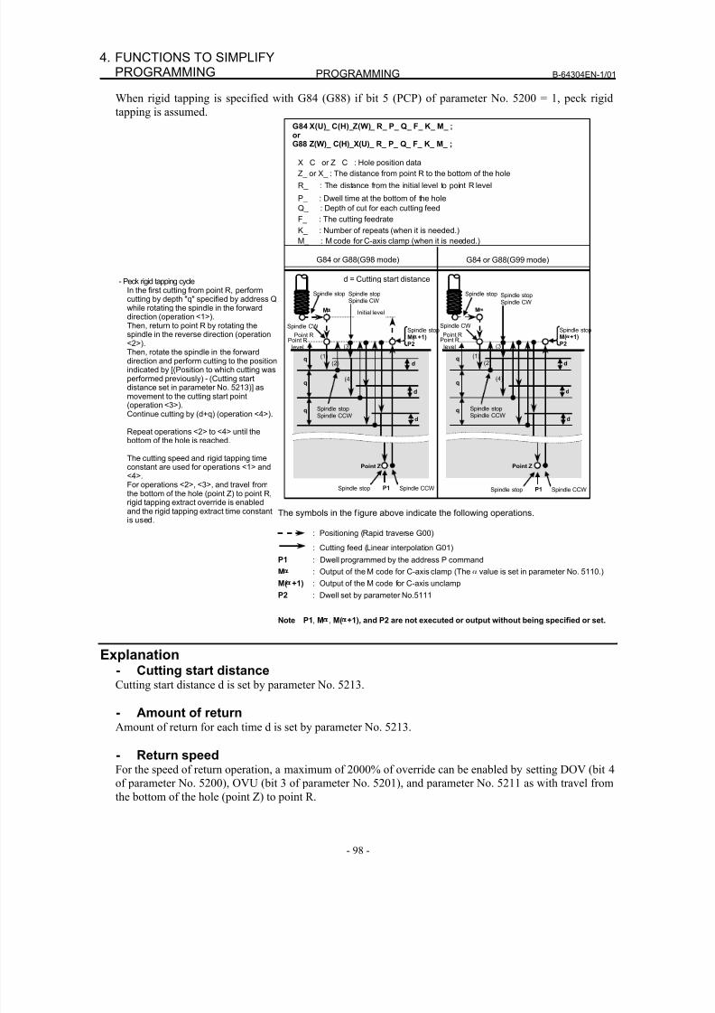
8/16/2019 Manual Operacion para FANUC
http://slidepdf.com/reader/full/manual-operacion-para-fanuc 116/435
PROGRAMMING B-64304EN-1/01
- 98 -
4. FUNCTIONS TO SIMPLIFYPROGRAMMING
When rigid tapping is specified with G84 (G88) if bit 5 (PCP) of parameter No. 5200 = 1, peck rigid
tapping is assumed.
G84 or G88(G98 mode) G84 or G88(G99 mode)
G84 X(U)_ C(H)_Z(W)_ R_ P_ Q_ F_ K_ M_ ;orG88 Z(W)_ C(H)_X(U)_ R_ P_ Q_ F_ K_ M_ ;
X_ C_ or Z_ C_ : Hole position data
Z_ or X_ : The distance from point R to the bottom of the hole
R_ : The distance from the initial level to point R level
P_ : Dwell time at the bottom of the hole
Q_ : Depth of cut for each cutting feed
F_ : The cutting feedrate
K_ : Number of repeats (when it is needed.)
d = Cutting start distance
M_ : M code for C-axis clamp (when it is needed.)
- Peck rigid tapping cycleIn the first cutting from point R, performcutting by depth "q" specified by address Qwhile rotating the spindle in the forward
direction (operation <1>).Then, return to point R by rotating thespindle in the reverse direction (operation<2>).Then, rotate the spindle in the forwarddirection and perform cutting to the positionindicated by [(Position to which cutting wasperformed previously) - (Cutting startdistance set in parameter No. 5213)] asmovement to the cutting start point(operation <3>).Continue cutting by (d+q) (operation <4>).
Repeat operations <2> to <4> until thebottom of the hole is reached.
The cutting speed and rigid tapping timeconstant are used for operations <1> and
<4>.For operations <2>, <3>, and travel fromthe bottom of the hole (point Z) to point R,rigid tapping extract override is enabledand the rigid tapping extract time constantis used.
Spindle stop
Point Z
q
q
M
(1)
d(2)
Initial level
Spindle stopM( +1)P2
Point Rlevel
Point R
(3)
(4)
d
d
q
P1Spindle stop
Spindle CW
Spindle CCW
Spindle stopSpindle CCW
Spindle stopSpindle CW
Point Z
q
q
M
(1)
d(2)
Spindle stopM( +1)P2
Point Rlevel
Point R
(3)
(4)
d
d
q
Spindle stop
P1Spindle stop
Spindle CW
Spindle CCW
Spindle stopSpindle CW
Spindle stopSpindle CCW
The symbols in the f igure above indicate the following operations.
: Positioning (Rapid traverse G00)
: Cutting feed (Linear interpolation G01)
P1 : Dwell programmed by the address P command
M : Output of the M code for C-axis clamp (The α value is set in parameter No. 5110.)
M( +1) : Output of the M code for C-axis unclamp
P2 : Dwell set by parameter No.5111
Note P1, M , M( +1), and P2 are not executed or output without being specified or set.
Explanation- Cutting start distance
Cutting start distance d is set by parameter No. 5213.
- Amount of return
Amount of return for each time d is set by parameter No. 5213.
- Return speed
For the speed of return operation, a maximum of 2000% of override can be enabled by setting DOV (bit 4
of parameter No. 5200), OVU (bit 3 of parameter No. 5201), and parameter No. 5211 as with travel from
the bottom of the hole (point Z) to point R.
8/16/2019 Manual Operacion para FANUC
http://slidepdf.com/reader/full/manual-operacion-para-fanuc 117/435
B-64304EN-1/01 PROGRAMMING
- 99 -
4.FUNCTIONS TO SIMPLIFYPROGRAMMING
- Speed during cutting into the cutting start pointFor the speed during cutting into the cutting start point, a maximum of 2000% of override can be enabled
by setting DOV (bit 4 of parameter No. 5200), OVU (bit 3 of parameter No. 5201), and parameter No.
5211 as with travel from the bottom of the hole (point Z) to point R.
- Acceleration/deceleration after interpolationLinear or bell-shaped acceleration/deceleration can be applied.
- Look-ahead acceleration/deceleration before interpolationLook-ahead acceleration/deceleration before interpolation is invalid.
- OverrideVarious types of override functions are invalid. The following override functions can be enabled by
setting corresponding parameters:
• Extraction override
• Override signal
Details are given later.
- Dry runDry run can be executed also in G84 (G88). When dry run is executed at the feedrate for the drilling axis
in G84 (G88), tapping is performed according to the feedrate. Note that the spindle speed becomes faster
at a higher dry run feedrate.
- Machine lockMachine lock can be executed also in G84 (G88).
When G84 (G88) is executed in the machine lock state, the tool does not move along the drilling axis.
Therefore, the spindle does not also rotate.
- ResetWhen a reset is performed during rigid tapping, the rigid tapping mode is canceled and the spindle motor
enters the normal mode. Note that the G84 (G88) mode is not canceled in this case when bit 6 (CLR) of
parameter No. 3402 is set.
- InterlockInterlock can also be applied in G84 (G88).
- Feed hold and single blockWhen parameter FHD (No. 5200#6) is set to 0, feed hold and single block are invalid in the G84 (G88)
mode. When this bit is set to 1, they are valid.
- Manual feedFor rigid tapping by manual handle feed, see the section "Rigid Tapping by Manual Handle."
With other manual operations, rigid tapping cannot be performed.
- Backlash compensationIn the rigid tapping mode, backlash compensation is applied to compensate the lost motion when the
spindle rotates clockwise or counterclockwise. Set the amount of backlash in parameters Nos. 5321 to
5324.
Along the drilling axis, backlash compensation has been applied.
- Series 10/11 formatWhen bit 1 (FCV) of parameter No. 0001 is set to 1, execution is enabled with G84.2. The same operation
as with G84 is performed. However, the command format for the repetitive count is L.
8/16/2019 Manual Operacion para FANUC
http://slidepdf.com/reader/full/manual-operacion-para-fanuc 118/435
PROGRAMMING B-64304EN-1/01
- 100 -
4. FUNCTIONS TO SIMPLIFYPROGRAMMING
Limitation- Axis switchingBefore the drilling axis can be changed, the canned cycle must be canceled. If the drilling axis is changed
in rigid mode, alarm PS0206 is issued.
- S commandsIf a speed higher than the maximum speed for the gear being used is specified, alarm PS0200 is issued.
When the rigid tapping canned cycle is cancelled, the S command used for rigid tapping is cleared to S0.
- Distribution amount for the spindleThe maximum distribution amount is 32,767 pulses per 8 msec for a serial spindle. (displayed on
diagnostic display No. 451)
This amount is changed according to the gear ratio setting for the position coder or rigid tapping
command. If a setting is made to exceed the upper limit, alarm PS0202 is issued.
- F commandSpecifying a value larger than the upper limit for cutting feed will cause alarm PS0011 to be issued.
- Unit of F commandMetric input Inch input Remarks
G98 1mm/min 0.01inch/min Decimal point programming allowed
G99 0.01mm/rev 0.0001inch/rev Decimal point programming allowed
- M29If an S command and axis movement are specified between M29 and G84, alarm PS0203 is issued. If
M29 is specified in a tapping cycle, alarm PS0204 is issued.
- Rigid tapping command M codeThe M code used to specify the rigid tapping mode is set in parameter No. 5210.
- P/QSpecify P and Q in a block that performs drilling. If they are specified in a block that does not perform
drilling, they are not stored as modal data.
When Q0 is specified, the peck rigid tapping cycle is not performed.
- CancelDo not specify a G code of the 01 group (G00 to G03) and G84 in a single block. Otherwise, G84 will be
canceled.
- Tool offsetIn the canned cycle mode, tool offsets are ignored.
- Subprogram callIn the canned cycle mode, specify the subprogram call command M98P_ in an independent block.
- d (parameter No.5213)Perform operation in the peck tapping cycle within point R. That is, set a value which does not exceed
point R for d (parameter No. 5213).
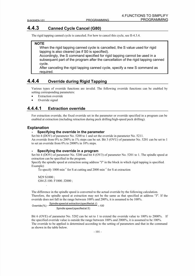
8/16/2019 Manual Operacion para FANUC
http://slidepdf.com/reader/full/manual-operacion-para-fanuc 119/435
B-64304EN-1/01 PROGRAMMING
- 101 -
4.FUNCTIONS TO SIMPLIFYPROGRAMMING
4.4.3 Canned Cycle Cancel (G80)
The rigid tapping canned cycle is canceled. For how to cancel this cycle, see II-4.3.4.
NOTEWhen the rigid tapping canned cycle is cancelled, the S value used for rigidtapping is also cleared (as if S0 is specified). Accordingly, the S command specified for rigid tapping cannot be used in asubsequent part of the program after the cancellation of the rigid tapping cannedcycle. After canceling the rigid tapping canned cycle, specify a new S command asrequired.
4.4.4 Override during Rigid Tapping
Various types of override functions are invalid. The following override functions can be enabled by
setting corresponding parameters:
• Extraction override
• Override signal
4.4.4.1 Extraction override
For extraction override, the fixed override set in the parameter or override specified in a program can be
enabled at extraction (including retraction during peck drilling/high-speed peck drilling).
Explanation- Specifying the override in the parameterSet bit 4 (DOV) of parameter No. 5200 to 1 and set the override in parameter No. 5211.
An override from 0% to 200% in 1% steps can be set. Bit 3 (OVU) of parameter No. 5201 can be set to 1
to set an override from 0% to 2000% in 10% steps.
- Specifying the override in a programSet bit 4 (DOV) of parameter No. 5200 and bit 4 (OV3) of parameter No. 5201 to 1. The spindle speed at
extraction can be specified in the program.
Specify the spindle speed at extraction using address "J" in the block in which rigid tapping is specified.
Example)
To specify 1000 min-1
for S at cutting and 2000 min-1
for S at extraction
.M29 S1000 ;
G84 Z-100. F1000. J2000 ;
.
The difference in the spindle speed is converted to the actual override by the following calculation.
Therefore, the spindle speed at extraction may not be the same as that specified at address "J". If the
override does not fall in the range between 100% and 200%, it is assumed to be 100%.
100
S
J ×=
)at(specifiedspeedSpindle
)at(specifiedextractionatspeedSpindle %)(Override
Bit 6 (OVE) of parameter No. 5202 can be set to 1 to extend the override value to 100% to 2000%. Ifthe specified override value is outside the range between 100% and 2000%, it is assumed to be 100%.
The override to be applied is determined according to the setting of parameters and that in the command
as shown in the table below.
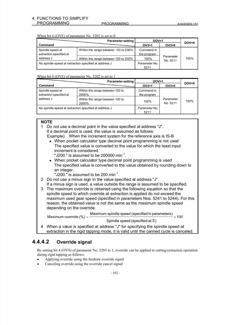
8/16/2019 Manual Operacion para FANUC
http://slidepdf.com/reader/full/manual-operacion-para-fanuc 120/435
PROGRAMMING B-64304EN-1/01
- 102 -
4. FUNCTIONS TO SIMPLIFYPROGRAMMING
When bit 6 (OVE) of parameter No. 5202 is set to 0
DOV=1Parameter setting
Command OV3=1 OV3=0DOV=0
Within the range between 100 to 200% Command inthe program
Spindle speed atextraction specified at
address J Within the range between 100 to 200% 100%
No spindle speed at extraction specified at address J Parameter No.
5211
Parameter
No. 5211100%
When bit 6 (OVE) of parameter No. 5202 is set to 1
DOV=1Parameter setting
Command OV3=1 OV3=0DOV=0
Within the range between 100 to
2000%
Command in
the program
Spindle speed at
extraction specified at
address J Within the range between 100 to
2000% 100%
No spindle speed at extraction specified at address J Parameter No.
5211
Parameter
No. 5211 100%
NOTE1 Do not use a decimal point in the value specified at address "J".
If a decimal point is used, the value is assumed as follows:Example) When the increment system for the reference axis is IS-B
• When pocket calculator type decimal point programming is not used
The specified value is converted to the value for which the least inputincrement is considered."J200." is assumed to be 200000 min-1.
• When pocket calculator type decimal point programming is used
The specified value is converted to the value obtained by rounding down toan integer."J200." is assumed to be 200 min-1.
2 Do not use a minus sign in the value specified at address "J".If a minus sign is used, a value outside the range is assumed to be specified.
3 The maximum override is obtained using the following equation so that thespindle speed to which override at extraction is applied do not exceed themaximum used gear speed (specified in parameters Nos. 5241 to 5244). For this
reason, the obtained value is not the same as the maximum spindle speeddepending on the override.
100
S
×=)at(specifiedspeedSpindle
)parametersin(specifiedspeedspindleMaximum(%)overrideMaximum
4 When a value is specified at address "J" for specifying the spindle speed atextraction in the rigid tapping mode, it is valid until the canned cycle is canceled.
4.4.4.2 Override signal
By setting bit 4 (OVS) of parameter No. 5203 to 1, override can be applied to cutting/extraction operation
during rigid tapping as follows:• Applying override using the feedrate override signal
• Canceling override using the override cancel signal
8/16/2019 Manual Operacion para FANUC
http://slidepdf.com/reader/full/manual-operacion-para-fanuc 121/435
B-64304EN-1/01 PROGRAMMING
- 103 -
4.FUNCTIONS TO SIMPLIFYPROGRAMMING
There are the following relationships between this function and override to each operation:
• At cutting
- When the override cancel signal is set to 0
Value specified by the override signal
- When the override cancel signal is set to 1100%
• At extraction
- When the override cancel signal is set to 0
Value specified by the override signal
- When the override cancel signal is set to 1 and extraction override is disabled
100%
- When the override cancel signal is set to 1 and extraction override is enabled
Value specified for extraction override
NOTE1 The maximum override is obtained using the following equation so that the
spindle speed to which override is applied do not exceed the maximum usedgear speed (specified in parameters Nos. 5241 to 5244). For this reason, theobtained value is not the same as the maximum spindle speed depending on theoverride.
100
S
×=)at(specifiedspeedSpindle
)parametersin(specifiedspeedspindleMaximum(%)overrideMaximum
2 Since override operation differs depending on the machine in use, refer to themanual provided by the machine tool builder.
4.5 CANNED GRINDING CYCLE (FOR GRINDING MACHINE)
With the canned grinding cycle, repetitive machining operations that are specific to grinding and are
usually specified using several blocks can be specified using one block including a G function. So, a
program can be created simply. At the same time, the size of a program can be reduced, and the memory
can be used more efficiently. Four types of canned grinding cycles are available:
• Traverse grinding cycle (G71)
(G72 when G code system C is used)
• Traverse direct constant-size grinding cycle (G72)
(G73 when G code system C is used)
• Oscillation grinding cycle (G73)
(G74 when G code system C is used)• Oscillation direct constant-size grinding cycle (G74)
(G75 when G code system C is used)
In the descriptions below, an axis used for cutting with a grinding wheel and an axis used for grinding
with a grinding wheel are referred to as follows:
Axis used for cutting with a grinding wheel: Cutting axis
Axis used for grinding with a grinding wheel: Grinding axis
For a depth of cut on a cutting axis and a distance of grinding on a grinding axis, the incremental system
(parameter No. 1013) for the reference axis (parameter No. 1031) is used. If 0 is set in parameter No.
1031 (reference axis), the incremental system for the first axis is used.
8/16/2019 Manual Operacion para FANUC
http://slidepdf.com/reader/full/manual-operacion-para-fanuc 122/435
PROGRAMMING B-64304EN-1/01
- 104 -
4. FUNCTIONS TO SIMPLIFYPROGRAMMING
NOTEThe canned grinding cycle is an optional function.The canned grinding cycle and multiple repetitive cycle cannot be usedsimultaneously for the same path.
To use the canned grinding cycle, set bit 0 (GFX) of parameter No. 5106 to 1.
WARNINGThe G codes for canned grinding cycles G71, G72, G73, and G74 (G72, G73,G74, and G75 when G code system C is used) are G codes of group 01. A Gcode for cancellation such as G80 used for a canned cycle for drilling isunavailable. By specifying a G code of group 00 other than G04, modalinformation such as a depth of cut is cleared but no canned grinding cycle canbe canceled. To cancel a canned grinding cycle, a G code of group 01 otherthan G71, G72, G73, and G74 needs to be specified. So, when switching toanother axis move command from G71, G72, G73 or G74, for example, be sureto specify a G code of group 01 such as G00 or G01 to cancel the cannedgrinding cycle. If another axis move command is specified without canceling thecanned grinding cycle, an unpredictable operation can result because ofcontinued cycle operation.
NOTE1 If the G code for a canned grinding cycle (G71, G72, G73, or G74) is specified,
the canned grinding cycle is executed according to the values of A, B, W, U, I,and K preserved as modal data while the cycle is valid, even if a block specifiedlater specifies none of G71, G72, G73, and G74.
Example:G71 A_ B_ W_ U_ I_ K_ H_ ;
; ← The canned grinding cycle is executed even if an empty block is
specified.%
2 When switching from a canned cycle for drilling to a canned grinding cycle,specify G80 to cancel the canned cycle for drilling.
3 When switching from a canned grinding cycle to another axis move command,cancel the canned cycle according to the warning above.
4 A canned grinding cycle and multiple repetitive canned cycle cannot be usedsimultaneously on the same path.
When the canned grinding cycle option is enabled, which function is to be used
can be selected using bit 0 (GFX) of parameter No. 5106.
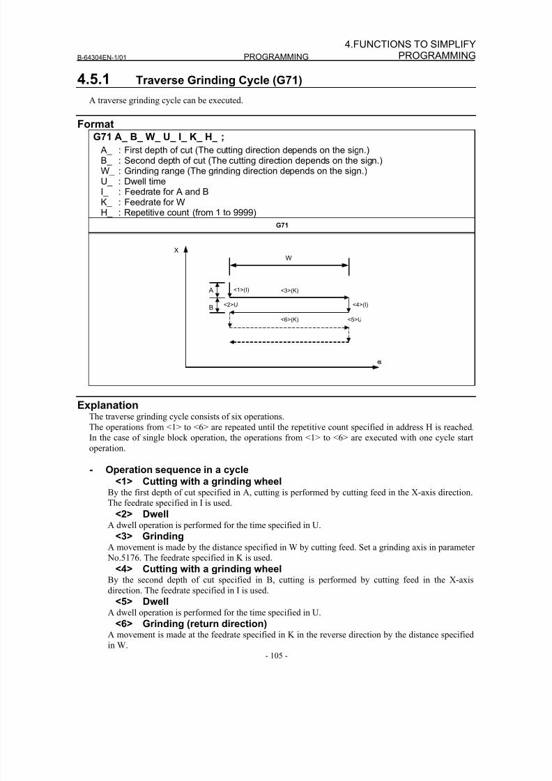
8/16/2019 Manual Operacion para FANUC
http://slidepdf.com/reader/full/manual-operacion-para-fanuc 123/435
B-64304EN-1/01 PROGRAMMING
- 105 -
4.FUNCTIONS TO SIMPLIFYPROGRAMMING
4.5.1 Traverse Grinding Cycle (G71)
A traverse grinding cycle can be executed.
FormatG71 A_ B_ W_ U_ I_ K_ H_ ;
A_ : First depth of cut (The cutting direction depends on the sign.)B_ : Second depth of cut (The cutting direction depends on the sign.)W_ : Grinding range (The grinding direction depends on the sign.)U_ : Dwell timeI_ : Feedrate for A and BK_ : Feedrate for WH_ : Repetitive count (from 1 to 9999)
G71
ExplanationThe traverse grinding cycle consists of six operations.
The operations from <1> to <6> are repeated until the repetitive count specified in address H is reached.
In the case of single block operation, the operations from <1> to <6> are executed with one cycle start
operation.
- Operation sequence in a cycle<1> Cutting with a grinding wheel
By the first depth of cut specified in A, cutting is performed by cutting feed in the X-axis direction.The feedrate specified in I is used.
<2> DwellA dwell operation is performed for the time specified in U.
<3> GrindingA movement is made by the distance specified in W by cutting feed. Set a grinding axis in parameter
No.5176. The feedrate specified in K is used.
<4> Cutting with a grinding wheelBy the second depth of cut specified in B, cutting is performed by cutting feed in the X-axis
direction. The feedrate specified in I is used.
<5> Dwell
A dwell operation is performed for the time specified in U.<6> Grinding (return direction)
A movement is made at the feedrate specified in K in the reverse direction by the distance specified
in W.
XW
A
B
<1>(I)
<2>U
<3>(K)
<4>(I)
<5>U<6>(K)
8/16/2019 Manual Operacion para FANUC
http://slidepdf.com/reader/full/manual-operacion-para-fanuc 124/435
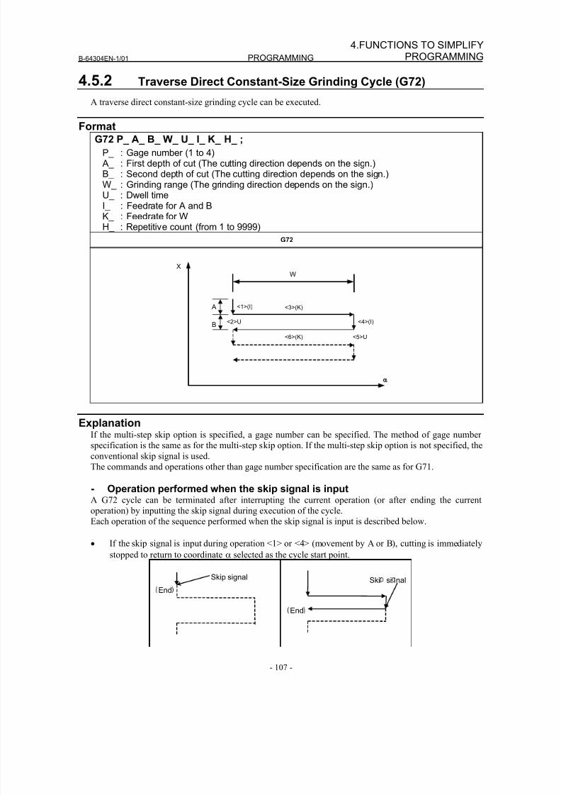
8/16/2019 Manual Operacion para FANUC
http://slidepdf.com/reader/full/manual-operacion-para-fanuc 125/435
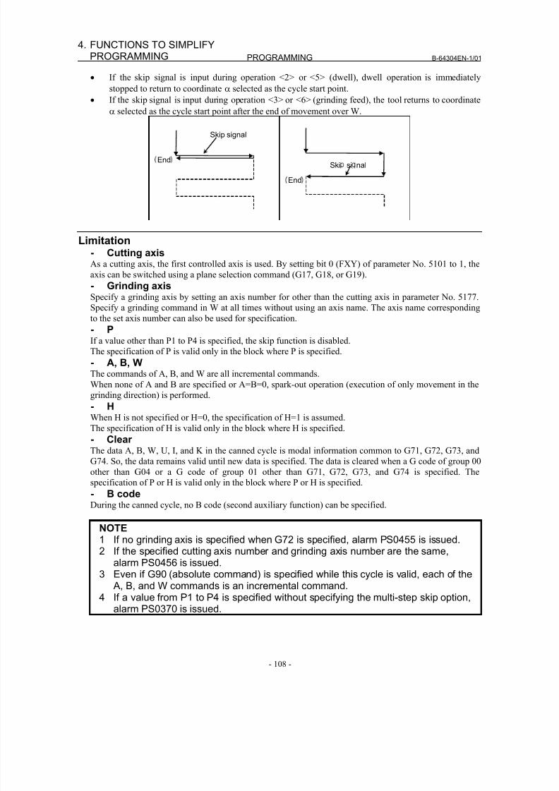
8/16/2019 Manual Operacion para FANUC
http://slidepdf.com/reader/full/manual-operacion-para-fanuc 126/435
PROGRAMMING B-64304EN-1/01
- 108 -
4. FUNCTIONS TO SIMPLIFYPROGRAMMING
• If the skip signal is input during operation <2> or <5> (dwell), dwell operation is immediately
stopped to return to coordinate α selected as the cycle start point.
• If the skip signal is input during operation <3> or <6> (grinding feed), the tool returns to coordinate
α selected as the cycle start point after the end of movement over W.
Limitation- Cutting axisAs a cutting axis, the first controlled axis is used. By setting bit 0 (FXY) of parameter No. 5101 to 1, the
axis can be switched using a plane selection command (G17, G18, or G19).
- Grinding axisSpecify a grinding axis by setting an axis number for other than the cutting axis in parameter No. 5177.
Specify a grinding command in W at all times without using an axis name. The axis name corresponding
to the set axis number can also be used for specification.
- PIf a value other than P1 to P4 is specified, the skip function is disabled.
The specification of P is valid only in the block where P is specified.
- A, B, W
The commands of A, B, and W are all incremental commands.When none of A and B are specified or A=B=0, spark-out operation (execution of only movement in the
grinding direction) is performed.
- HWhen H is not specified or H=0, the specification of H=1 is assumed.
The specification of H is valid only in the block where H is specified.
- ClearThe data A, B, W, U, I, and K in the canned cycle is modal information common to G71, G72, G73, and
G74. So, the data remains valid until new data is specified. The data is cleared when a G code of group 00
other than G04 or a G code of group 01 other than G71, G72, G73, and G74 is specified. The
specification of P or H is valid only in the block where P or H is specified.
- B codeDuring the canned cycle, no B code (second auxiliary function) can be specified.
NOTE1 If no grinding axis is specified when G72 is specified, alarm PS0455 is issued.2 If the specified cutting axis number and grinding axis number are the same,
alarm PS0456 is issued.3 Even if G90 (absolute command) is specified while this cycle is valid, each of the
A, B, and W commands is an incremental command.4 If a value from P1 to P4 is specified without specifying the multi-step skip option,
alarm PS0370 is issued.
End
Skip signal
Ski si nal
End
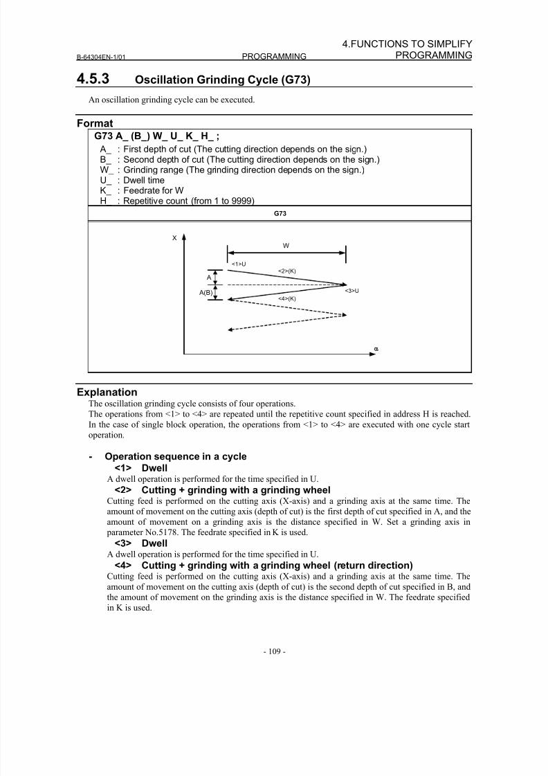
8/16/2019 Manual Operacion para FANUC
http://slidepdf.com/reader/full/manual-operacion-para-fanuc 127/435
B-64304EN-1/01 PROGRAMMING
- 109 -
4.FUNCTIONS TO SIMPLIFYPROGRAMMING
4.5.3 Oscillation Grinding Cycle (G73)
An oscillation grinding cycle can be executed.
FormatG73 A_ (B_) W_ U_ K_ H_ ;
A_ : First depth of cut (The cutting direction depends on the sign.)B_ : Second depth of cut (The cutting direction depends on the sign.)W_ : Grinding range (The grinding direction depends on the sign.)U_ : Dwell timeK_ : Feedrate for WH_ : Repetitive count (from 1 to 9999)
G73
ExplanationThe oscillation grinding cycle consists of four operations.
The operations from <1> to <4> are repeated until the repetitive count specified in address H is reached.
In the case of single block operation, the operations from <1> to <4> are executed with one cycle start
operation.
- Operation sequence in a cycle<1> Dwell
A dwell operation is performed for the time specified in U.
<2> Cutting + grinding with a grinding wheelCutting feed is performed on the cutting axis (X-axis) and a grinding axis at the same time. The
amount of movement on the cutting axis (depth of cut) is the first depth of cut specified in A, and the
amount of movement on a grinding axis is the distance specified in W. Set a grinding axis in
parameter No.5178. The feedrate specified in K is used.
<3> DwellA dwell operation is performed for the time specified in U.
<4> Cutting + grinding with a grinding wheel (return direction)Cutting feed is performed on the cutting axis (X-axis) and a grinding axis at the same time. The
amount of movement on the cutting axis (depth of cut) is the second depth of cut specified in B, and
the amount of movement on the grinding axis is the distance specified in W. The feedrate specified
in K is used.
X
W
A
A(B)
<1>U
<2>(K)
<3>U
<4>(K)
8/16/2019 Manual Operacion para FANUC
http://slidepdf.com/reader/full/manual-operacion-para-fanuc 128/435
PROGRAMMING B-64304EN-1/01
- 110 -
4. FUNCTIONS TO SIMPLIFYPROGRAMMING
Limitation- Cutting axisAs a cutting axis, the first controlled axis is used. By setting bit 0 (FXY) of parameter No. 5101 to 1, the
axis can be switched using a plane selection command (G17, G18, or G19).
- Grinding axisSpecify a grinding axis by setting an axis number for other than the cutting axis in parameter No. 5178.
Specify a grinding command in W at all times without using an axis name. The axis name corresponding
to the set axis number can also be used for specification.
- BIf B is not specified, B=A is assumed.
The specification of B is valid only in the block where B is specified.
- A, B, WThe commands of A, B, and W are all incremental commands.
When none of A and B are specified or A=B=0, spark-out operation (execution of only movement in the
grinding direction) is performed.
- HWhen H is not specified or H=0, the specification of H=1 is assumed.
The specification of H is valid only in the block where H is specified.
- ClearThe data A, W, U, and K in the canned cycle is modal information common to G71, G72, G73, and G74.
So, the data remains valid until new data is specified. The data is cleared when a G code of group 00 other
than G04 or a G code of group 01 other than G71, G72, G73, and G74 is specified. The specification of B
or H is valid only in the block where B or H is specified.
- B codeDuring the canned cycle, no B code (second auxiliary function) can be specified.
NOTE1 If no grinding axis is specified when G73 is specified, alarm PS0455 is issued.2 If the specified cutting axis number and grinding axis number are the same,
alarm PS0456 is issued.3 Even if G90 (absolute command) is specified while this cycle is valid, each of the
A, B, and W commands is an incremental command.
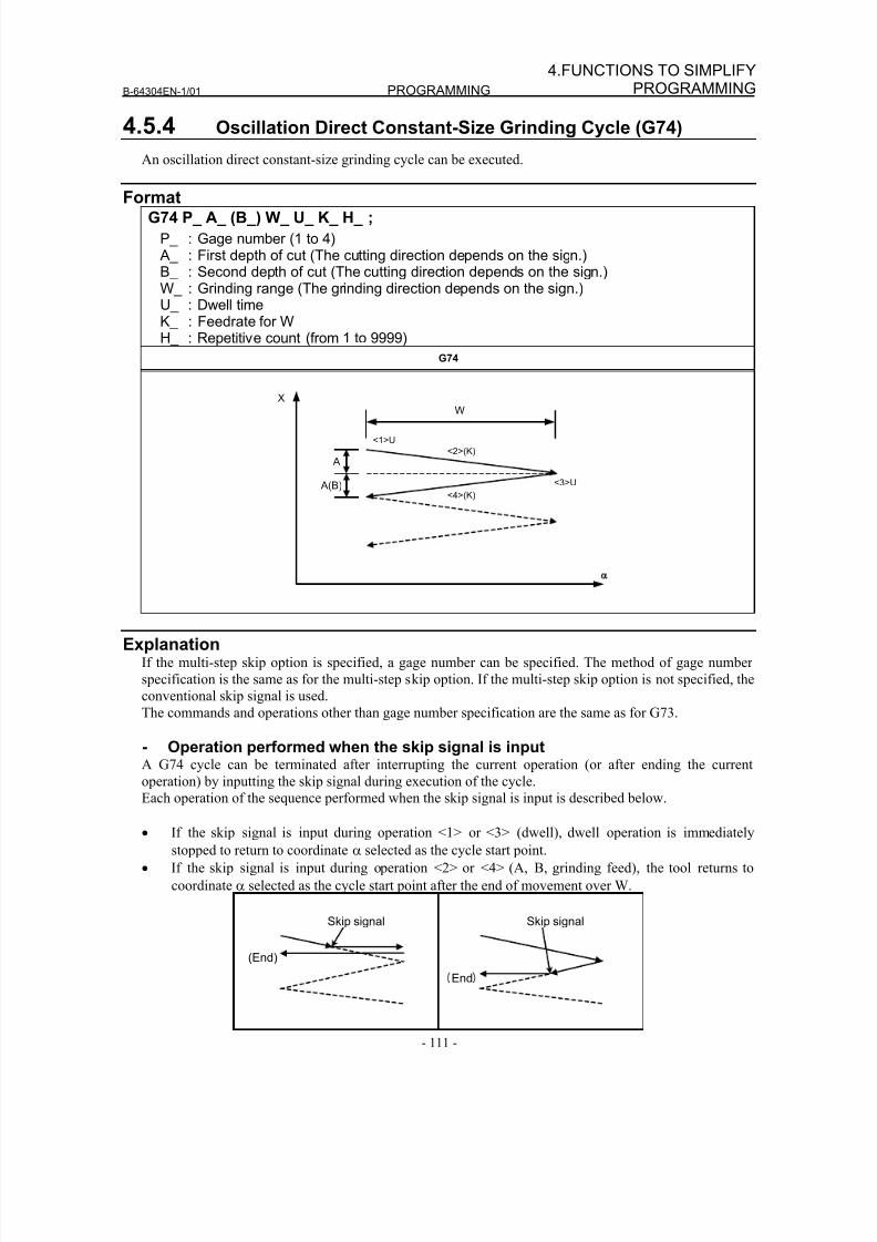
8/16/2019 Manual Operacion para FANUC
http://slidepdf.com/reader/full/manual-operacion-para-fanuc 129/435
B-64304EN-1/01 PROGRAMMING
- 111 -
4.FUNCTIONS TO SIMPLIFYPROGRAMMING
4.5.4 Oscillation Direct Constant-Size Grinding Cycle (G74)
An oscillation direct constant-size grinding cycle can be executed.
FormatG74 P_ A_ (B_) W_ U_ K_ H_ ;
P_ : Gage number (1 to 4) A_ : First depth of cut (The cutting direction depends on the sign.)B_ : Second depth of cut (The cutting direction depends on the sign.)W_ : Grinding range (The grinding direction depends on the sign.)U_ : Dwell timeK_ : Feedrate for WH_ : Repetitive count (from 1 to 9999)
G74
ExplanationIf the multi-step skip option is specified, a gage number can be specified. The method of gage number
specification is the same as for the multi-step skip option. If the multi-step skip option is not specified, the
conventional skip signal is used.
The commands and operations other than gage number specification are the same as for G73.
- Operation performed when the skip signal is inputA G74 cycle can be terminated after interrupting the current operation (or after ending the current
operation) by inputting the skip signal during execution of the cycle.Each operation of the sequence performed when the skip signal is input is described below.
• If the skip signal is input during operation <1> or <3> (dwell), dwell operation is immediately
stopped to return to coordinate α selected as the cycle start point.
• If the skip signal is input during operation <2> or <4> (A, B, grinding feed), the tool returns to
coordinate α selected as the cycle start point after the end of movement over W.
XW
A
A(B)
<1>U
<2>(K)
<3>U
<4>(K)
(End)
Skip signal
End
Skip signal
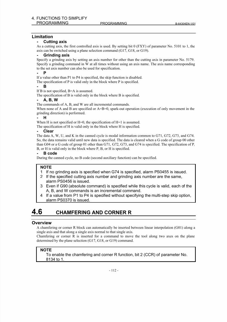
8/16/2019 Manual Operacion para FANUC
http://slidepdf.com/reader/full/manual-operacion-para-fanuc 130/435
PROGRAMMING B-64304EN-1/01
- 112 -
4. FUNCTIONS TO SIMPLIFYPROGRAMMING
Limitation- Cutting axisAs a cutting axis, the first controlled axis is used. By setting bit 0 (FXY) of parameter No. 5101 to 1, the
axis can be switched using a plane selection command (G17, G18, or G19).- Grinding axisSpecify a grinding axis by setting an axis number for other than the cutting axis in parameter No. 5179.
Specify a grinding command in W at all times without using an axis name. The axis name corresponding
to the set axis number can also be used for specification.
- PIf a value other than P1 to P4 is specified, the skip function is disabled.
The specification of P is valid only in the block where P is specified.
- BIf B is not specified, B=A is assumed.
The specification of B is valid only in the block where B is specified.
- A, B, WThe commands of A, B, and W are all incremental commands.
When none of A and B are specified or A=B=0, spark-out operation (execution of only movement in the
grinding direction) is performed.
- HWhen H is not specified or H=0, the specification of H=1 is assumed.
The specification of H is valid only in the block where H is specified.
- ClearThe data A, W, U, and K in the canned cycle is modal information common to G71, G72, G73, and G74.
So, the data remains valid until new data is specified. The data is cleared when a G code of group 00 other
than G04 or a G code of group 01 other than G71, G72, G73, and G74 is specified. The specification of P,
B, or H is valid only in the block where P, B, or H is specified.
- B codeDuring the canned cycle, no B code (second auxiliary function) can be specified.
NOTE1 If no grinding axis is specified when G74 is specified, alarm PS0455 is issued.2 If the specified cutting axis number and grinding axis number are the same,
alarm PS0456 is issued.3 Even if G90 (absolute command) is specified while this cycle is valid, each of the
A, B, and W commands is an incremental command.4 If a value from P1 to P4 is specified without specifying the multi-step skip option,
alarm PS0370 is issued.
4.6 CHAMFERING AND CORNER R
OverviewA chamfering or corner R block can automatically be inserted between linear interpolation (G01) along a
single axis and that along a single axis normal to that single axis.
Chamfering or corner R is inserted for a command to move the tool along two axes on the plane
determined by the plane selection (G17, G18, or G19) command.
NOTETo enable the chamfering and corner R function, bit 2 (CCR) of parameter No.8134 to 1.
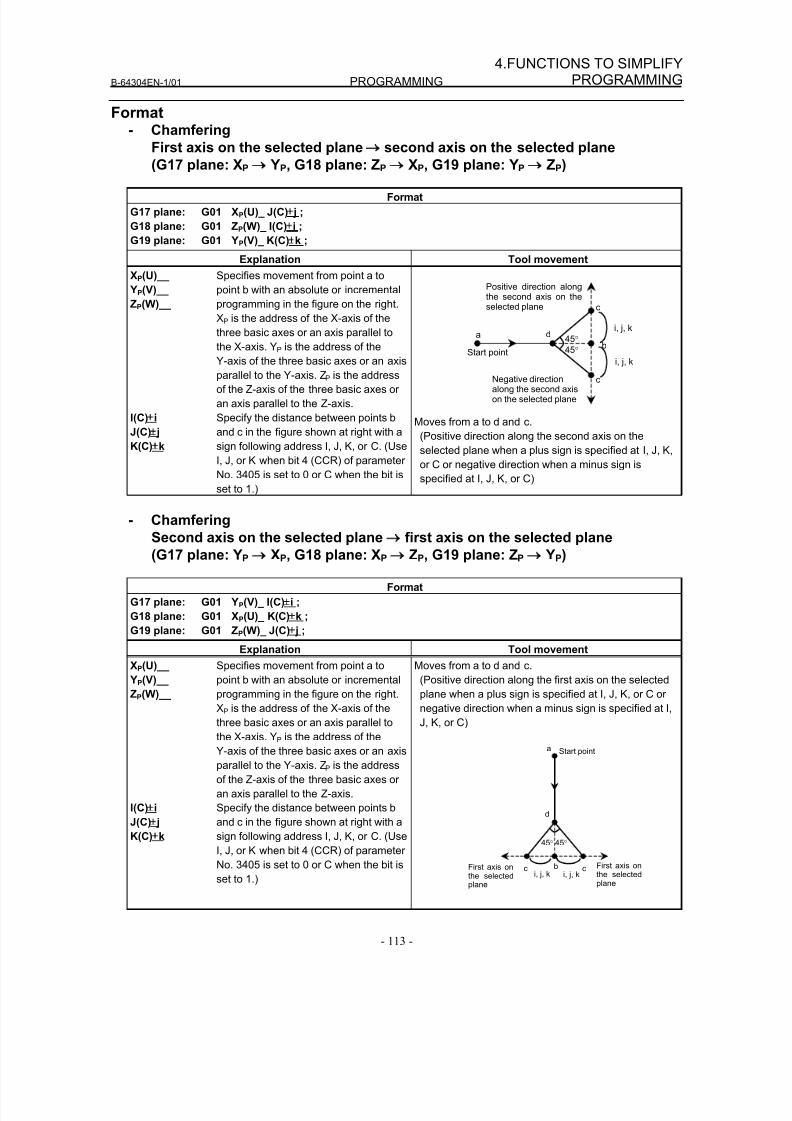
8/16/2019 Manual Operacion para FANUC
http://slidepdf.com/reader/full/manual-operacion-para-fanuc 131/435
B-64304EN-1/01 PROGRAMMING
- 113 -
4.FUNCTIONS TO SIMPLIFYPROGRAMMING
Format- Chamfering
First axis on the selected plane → second axis on the selected plane
(G17 plane: XP → YP, G18 plane: ZP → XP, G19 plane: YP → ZP)
Format
G17 plane: G01 XP(U)_ J(C)± j ;
G18 plane: G01 ZP(W)_ I(C)±i ;
G19 plane: G01 YP(V)_ K(C)±k ;
Explanation Tool movement
XP(U)__
YP(V)__
ZP(W)__
Specifies movement from point a to
point b with an absolute or incremental
programming in the figure on the right.
XP is the address of the X-axis of the
three basic axes or an axis parallel to
the X-axis. YP is the address of theY-axis of the three basic axes or an axis
parallel to the Y-axis. ZP is the address
of the Z-axis of the three basic axes or
an axis parallel to the Z-axis.
I(C)±i
J(C)± j
K(C)±k
Specify the distance between points b
and c in the figure shown at right with a
sign following address I, J, K, or C. (Use
I, J, or K when bit 4 (CCR) of parameter
No. 3405 is set to 0 or C when the bit is
set to 1.)
a d
c
c
b
i, j, k
i, j, k
45°
45°
Positive direction alongthe second axis on theselected plane
Negative directionalong the second axison the selected plane
Start point
Moves from a to d and c.
(Positive direction along the second axis on the
selected plane when a plus sign is specified at I, J, K,
or C or negative direction when a minus sign is
specified at I, J, K, or C)
- Chamfering
Second axis on the selected plane → first axis on the selected plane
(G17 plane: YP → XP, G18 plane: XP → ZP, G19 plane: ZP → YP)
Format
G17 plane: G01 YP(V)_ I(C)±i ;
G18 plane: G01 XP(U)_ K(C)±k ;
G19 plane: G01 ZP(W)_ J(C)± j ;
Explanation Tool movement
XP(U)__
YP(V)__
ZP(W)__
Specifies movement from point a to
point b with an absolute or incremental
programming in the figure on the right.
XP is the address of the X-axis of the
three basic axes or an axis parallel to
the X-axis. YP is the address of the
Y-axis of the three basic axes or an axis
parallel to the Y-axis. ZP is the address
of the Z-axis of the three basic axes or
an axis parallel to the Z-axis.
I(C)±
i
J(C)± j
K(C)±k
Specify the distance between points b
and c in the figure shown at right with a
sign following address I, J, K, or C. (Use
I, J, or K when bit 4 (CCR) of parameter
No. 3405 is set to 0 or C when the bit is
set to 1.)
Moves from a to d and c.
(Positive direction along the first axis on the selected
plane when a plus sign is specified at I, J, K, or C or
negative direction when a minus sign is specified at I,
J, K, or C)
a
d
c cb i, j, ki, j, k
45°
First axis onthe selected
plane
45°
First axis onthe selectedplane
Start point
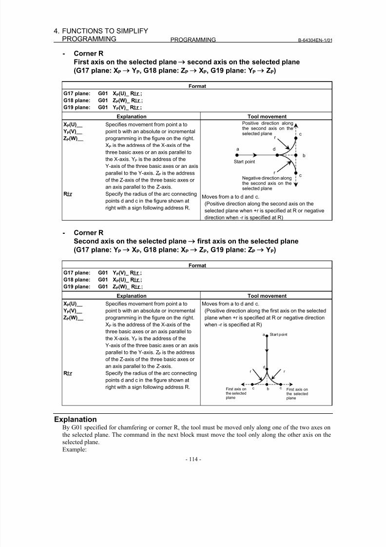
8/16/2019 Manual Operacion para FANUC
http://slidepdf.com/reader/full/manual-operacion-para-fanuc 132/435
PROGRAMMING B-64304EN-1/01
- 114 -
4. FUNCTIONS TO SIMPLIFYPROGRAMMING
- Corner R
First axis on the selected plane → second axis on the selected plane
(G17 plane: XP → YP, G18 plane: ZP → XP, G19 plane: YP → ZP)
FormatG17 plane: G01 XP(U)_ R
±
r ;
G18 plane: G01 ZP(W)_ R±
r ;
G19 plane: G01 YP(V)_ R±
r ;
Explanation Tool movement
XP(U)__
YP(V)__
ZP(W)__
Specifies movement from point a to
point b with an absolute or incremental
programming in the figure on the right.
XP is the address of the X-axis of the
three basic axes or an axis parallel to
the X-axis. YP is the address of the
Y-axis of the three basic axes or an axis
parallel to the Y-axis. ZP is the addressof the Z-axis of the three basic axes or
an axis parallel to the Z-axis.
R±
r Specify the radius of the arc connecting
points d and c in the figure shown at
right with a sign following address R.
a d
c
c
b
r
r
Positive direction alongthe second axis on theselected plane
Negative direction alongthe second axis on theselected plane
Start point
Moves from a to d and c.
(Positive direction along the second axis on the
selected plane when +r is specified at R or negative
direction when -r is specified at R)
- Corner R
Second axis on the selected plane → first axis on the selected plane
(G17 plane: YP → XP, G18 plane: XP → ZP, G19 plane: ZP → YP)
Format
G17 plane: G01 YP(V)_ R±
r ;
G18 plane: G01 XP(U)_ R±
r ;
G19 plane: G01 ZP(W)_ R±
r ;
Explanation Tool movement
XP(U)__
YP(V)__
ZP(W)__
Specifies movement from point a to
point b with an absolute or incremental
programming in the figure on the right.
XP is the address of the X-axis of the
three basic axes or an axis parallel to
the X-axis. YP is the address of the
Y-axis of the three basic axes or an axis
parallel to the Y-axis. ZP is the address
of the Z-axis of the three basic axes or
an axis parallel to the Z-axis.
R±r Specify the radius of the arc connecting
points d and c in the figure shown at
right with a sign following address R.
Moves from a to d and c.
(Positive direction along the first axis on the selected
plane when +r is specified at R or negative direction
when -r is specified at R)
d
c c b
r r
First axis onthe selectedplane
First axis onthe selectedplane
a Start point
Explanation
By G01 specified for chamfering or corner R, the tool must be moved only along one of the two axes onthe selected plane. The command in the next block must move the tool only along the other axis on the
selected plane.
Example:
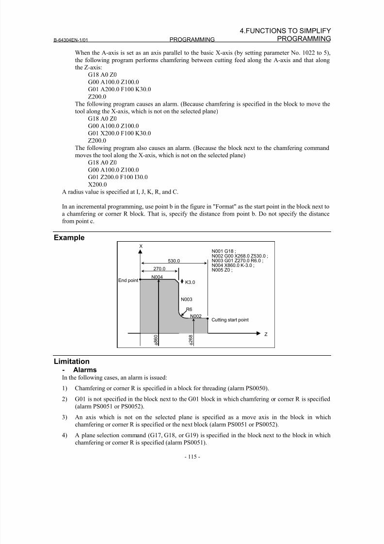
8/16/2019 Manual Operacion para FANUC
http://slidepdf.com/reader/full/manual-operacion-para-fanuc 133/435
B-64304EN-1/01 PROGRAMMING
- 115 -
4.FUNCTIONS TO SIMPLIFYPROGRAMMING
When the A-axis is set as an axis parallel to the basic X-axis (by setting parameter No. 1022 to 5),
the following program performs chamfering between cutting feed along the A-axis and that along
the Z-axis:
G18 A0 Z0
G00 A100.0 Z100.0
G01 A200.0 F100 K30.0
Z200.0
The following program causes an alarm. (Because chamfering is specified in the block to move the
tool along the X-axis, which is not on the selected plane)
G18 A0 Z0
G00 A100.0 Z100.0
G01 X200.0 F100 K30.0
Z200.0
The following program also causes an alarm. (Because the block next to the chamfering command
moves the tool along the X-axis, which is not on the selected plane)
G18 A0 Z0
G00 A100.0 Z100.0G01 Z200.0 F100 I30.0
X200.0
A radius value is specified at I, J, K, R, and C.
In an incremental programming, use point b in the figure in "Format" as the start point in the block next to
a chamfering or corner R block. That is, specify the distance from point b. Do not specify the distance
from point c.
Example
270.0
K3.0
Cutting start point
End point
530.0
X
Z
φ 8
6 0
φ 2
6 8
N003
N004
N002
R6
N001 G18 ;
N002 G00 X268.0 Z530.0 ;N003 G01 Z270.0 R6.0 ;N004 X860.0 K-3.0 ;N005 Z0 ;
Limitation- AlarmsIn the following cases, an alarm is issued:
1) Chamfering or corner R is specified in a block for threading (alarm PS0050).
2) G01 is not specified in the block next to the G01 block in which chamfering or corner R is specified
(alarm PS0051 or PS0052).
3) An axis which is not on the selected plane is specified as a move axis in the block in which
chamfering or corner R is specified or the next block (alarm PS0051 or PS0052).4) A plane selection command (G17, G18, or G19) is specified in the block next to the block in which
chamfering or corner R is specified (alarm PS0051).
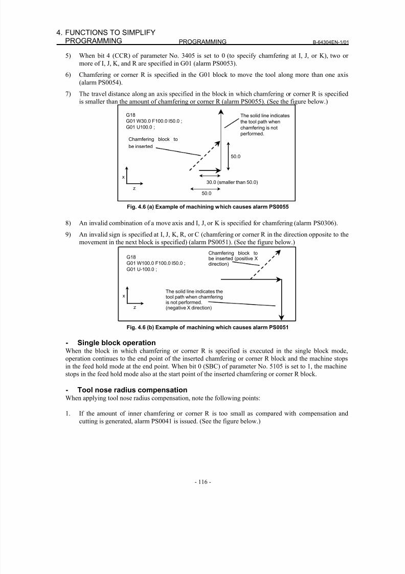
8/16/2019 Manual Operacion para FANUC
http://slidepdf.com/reader/full/manual-operacion-para-fanuc 134/435
PROGRAMMING B-64304EN-1/01
- 116 -
4. FUNCTIONS TO SIMPLIFYPROGRAMMING
5) When bit 4 (CCR) of parameter No. 3405 is set to 0 (to specify chamfering at I, J, or K), two or
more of I, J, K, and R are specified in G01 (alarm PS0053).
6) Chamfering or corner R is specified in the G01 block to move the tool along more than one axis
(alarm PS0054).
7) The travel distance along an axis specified in the block in which chamfering or corner R is specified
is smaller than the amount of chamfering or corner R (alarm PS0055). (See the figure below.)
The solid line indicates
the tool path when
chamfering is not
performed.
50.0
G18
G01 W30.0 F100.0 I50.0 ;
G01 U100.0 ;
z
x
Chamfering block to
be inserted
50.0
30.0 (smaller than 50.0)
Fig. 4.6 (a) Example of machining which causes alarm PS0055
8) An invalid combination of a move axis and I, J, or K is specified for chamfering (alarm PS0306).
9) An invalid sign is specified at I, J, K, R, or C (chamfering or corner R in the direction opposite to the
movement in the next block is specified) (alarm PS0051). (See the figure below.)
The solid line indicates thetool path when chamferingis not performed.(negative X direction)
G18
G01 W100.0 F100.0 I50.0 ;
G01 U-100.0 ;
z
x
Chamfering block tobe inserted (positive Xdirection)
Fig. 4.6 (b) Example of machining which causes alarm PS0051
- Single block operationWhen the block in which chamfering or corner R is specified is executed in the single block mode,
operation continues to the end point of the inserted chamfering or corner R block and the machine stopsin the feed hold mode at the end point. When bit 0 (SBC) of parameter No. 5105 is set to 1, the machine
stops in the feed hold mode also at the start point of the inserted chamfering or corner R block.
- Tool nose radius compensationWhen applying tool nose radius compensation, note the following points:
1. If the amount of inner chamfering or corner R is too small as compared with compensation and
cutting is generated, alarm PS0041 is issued. (See the figure below.)
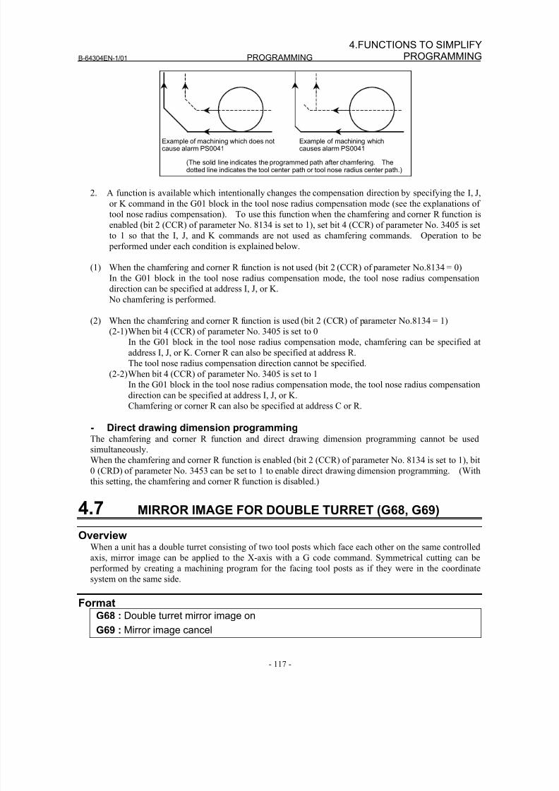
8/16/2019 Manual Operacion para FANUC
http://slidepdf.com/reader/full/manual-operacion-para-fanuc 135/435
B-64304EN-1/01 PROGRAMMING
- 117 -
4.FUNCTIONS TO SIMPLIFYPROGRAMMING
Example of machining which does notcause alarm PS0041
Example of machining whichcauses alarm PS0041
(The solid line indicates the programmed path after chamfering. Thedotted line indicates the tool center path or tool nose radius center path.)
2. A function is available which intentionally changes the compensation direction by specifying the I, J,
or K command in the G01 block in the tool nose radius compensation mode (see the explanations of
tool nose radius compensation). To use this function when the chamfering and corner R function is
enabled (bit 2 (CCR) of parameter No. 8134 is set to 1), set bit 4 (CCR) of parameter No. 3405 is set
to 1 so that the I, J, and K commands are not used as chamfering commands. Operation to be
performed under each condition is explained below.
(1) When the chamfering and corner R function is not used (bit 2 (CCR) of parameter No.8134 = 0)
In the G01 block in the tool nose radius compensation mode, the tool nose radius compensation
direction can be specified at address I, J, or K.
No chamfering is performed.
(2) When the chamfering and corner R function is used (bit 2 (CCR) of parameter No.8134 = 1)
(2-1) When bit 4 (CCR) of parameter No. 3405 is set to 0
In the G01 block in the tool nose radius compensation mode, chamfering can be specified at
address I, J, or K. Corner R can also be specified at address R.
The tool nose radius compensation direction cannot be specified.
(2-2) When bit 4 (CCR) of parameter No. 3405 is set to 1In the G01 block in the tool nose radius compensation mode, the tool nose radius compensation
direction can be specified at address I, J, or K.
Chamfering or corner R can also be specified at address C or R.
- Direct drawing dimension programmingThe chamfering and corner R function and direct drawing dimension programming cannot be used
simultaneously.
When the chamfering and corner R function is enabled (bit 2 (CCR) of parameter No. 8134 is set to 1), bit
0 (CRD) of parameter No. 3453 can be set to 1 to enable direct drawing dimension programming. (With
this setting, the chamfering and corner R function is disabled.)
4.7 MIRROR IMAGE FOR DOUBLE TURRET (G68, G69)
OverviewWhen a unit has a double turret consisting of two tool posts which face each other on the same controlled
axis, mirror image can be applied to the X-axis with a G code command. Symmetrical cutting can be
performed by creating a machining program for the facing tool posts as if they were in the coordinate
system on the same side.
FormatG68 : Double turret mirror image on
G69 : Mirror image cancel
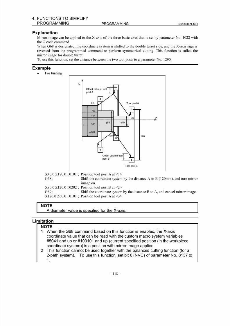
8/16/2019 Manual Operacion para FANUC
http://slidepdf.com/reader/full/manual-operacion-para-fanuc 136/435
PROGRAMMING B-64304EN-1/01
- 118 -
4. FUNCTIONS TO SIMPLIFYPROGRAMMING
ExplanationMirror image can be applied to the X-axis of the three basic axes that is set by parameter No. 1022 with
the G code command.
When G68 is designated, the coordinate system is shifted to the double turret side, and the X-axis sign is
reversed from the programmed command to perform symmetrical cutting. This function is called themirror image for double turret.
To use this function, set the distance between the two tool posts to a parameter No. 1290.
Example• For turning
Offset value of tool
post B
Tool post B
120
120
60
180
Z
φ120
φ80 φ40
X
<1>
<2>
Offset value of tool
post A
Tool post A<3>
X40.0 Z180.0 T0101 ; Position tool post A at <1>
G68 ; Shift the coordinate system by the distance A to B (120mm), and turn mirror
image on.
X80.0 Z120.0 T0202 ; Position tool post B at <2>
G69 ; Shift the coordinate system by the distance B to A, and cancel mirror image.
X120.0 Z60.0 T0101 ; Position tool post A at <3>
NOTE A diameter value is specified for the X-axis.
Limitation
NOTE1 When the G68 command based on this function is enabled, the X-axis
coordinate value that can be read with the custom macro system variables#5041 and up or #100101 and up (current specified position (in the workpiececoordinate system)) is a position with mirror image applied.
2 This function cannot be used together with the balanced cutting function (for a
2-path system). To use this function, set bit 0 (NVC) of parameter No. 8137 to1.
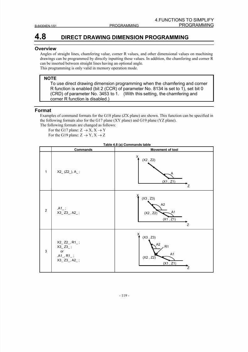
8/16/2019 Manual Operacion para FANUC
http://slidepdf.com/reader/full/manual-operacion-para-fanuc 137/435
B-64304EN-1/01 PROGRAMMING
- 119 -
4.FUNCTIONS TO SIMPLIFYPROGRAMMING
4.8 DIRECT DRAWING DIMENSION PROGRAMMING
Overview
Angles of straight lines, chamfering value, corner R values, and other dimensional values on machiningdrawings can be programmed by directly inputting these values. In addition, the chamfering and corner R
can be inserted between straight lines having an optional angle.
This programming is only valid in memory operation mode.
NOTETo use direct drawing dimension programming when the chamfering and cornerR function is enabled (bit 2 (CCR) of parameter No. 8134 is set to 1), set bit 0(CRD) of parameter No. 3453 to 1. (With this setting, the chamfering andcorner R function is disabled.)
FormatExamples of command formats for the G18 plane (ZX plane) are shown. This function can be specified in
the following formats also for the G17 plane (XY plane) and G19 plane (YZ plane).
The following formats are changed as follows:
For the G17 plane: Z → X, X → Y
For the G19 plane: Z → Y, X → Z
Table 4.8 (a) Commands table
Commands Movement of tool
1 X2_ (Z2_), A_ ;
(X1 , Z1)
(X2 , Z2)
A
X
Z
2,A1_ ;
X3_ Z3_, A2_ ;
(X1 , Z1)
(X3 , Z3)
(X2 , Z2)
X
Z
A1
A2
3
X2_ Z2_, R1_ ;
X3_ Z3_ ;
or
,A1_, R1_ ;
X3_ Z3_, A2_ ;(X1 , Z1)
(X3 , Z3)
(X2 , Z2)
X
Z
A1
A2R1
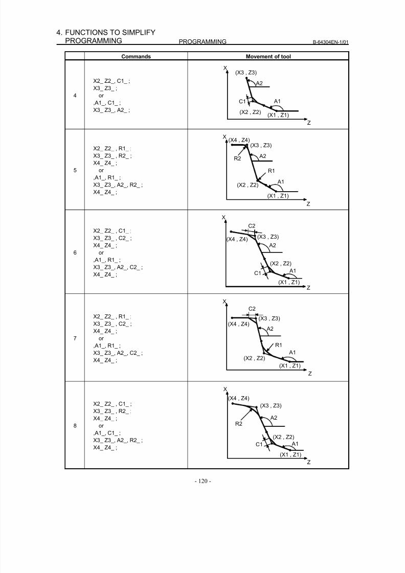
8/16/2019 Manual Operacion para FANUC
http://slidepdf.com/reader/full/manual-operacion-para-fanuc 138/435
PROGRAMMING B-64304EN-1/01
- 120 -
4. FUNCTIONS TO SIMPLIFYPROGRAMMING
Commands Movement of tool
4
X2_ Z2_, C1_ ;
X3_ Z3_ ;or
,A1_, C1_ ;
X3_ Z3_, A2_ ;(X1 , Z1)
(X3 , Z3)
(X2 , Z2)
X
Z
A1
A2
C1
5
X2_ Z2_ , R1_ ;
X3_ Z3_ , R2_ ;
X4_ Z4_ ;
or
,A1_, R1_ ;X3_ Z3_, A2_, R2_ ;
X4_ Z4_ ;(X1 , Z1)
X
Z
A1
R1
A2
(X3 , Z3)(X4 , Z4)
R2
(X2 , Z2)
6
X2_ Z2_ , C1_ ;
X3_ Z3_ , C2_ ;
X4_ Z4_ ;
or
,A1_, R1_ ;
X3_ Z3_, A2_, C2_ ;X4_ Z4_ ;
(X1 , Z1)
(X3 , Z3)
(X2 , Z2)
X
Z
A1
A2
C1
(X4 , Z4)
C2
7
X2_ Z2_ , R1_ ;
X3_ Z3_ , C2_ ;
X4_ Z4_ ;
or
,A1_, R1_ ;
X3_ Z3_, A2_, C2_ ;
X4_ Z4_ ;(X1 , Z1)
(X3 , Z3)
(X2 , Z2)
X
Z
A2(X4 , Z4)
C2
A1
R1
8
X2_ Z2_ , C1_ ;
X3_ Z3_ , R2_ ;
X4_ Z4_ ;
or
,A1_, C1_ ;
X3_ Z3_, A2_, R2_ ;
X4_ Z4_ ; (X1 , Z1)
(X3 , Z3)
(X2 , Z2)
X
Z
A1
A2
C1
(X4 , Z4)
R2
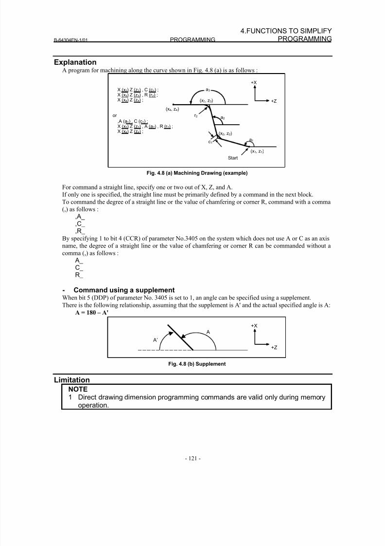
8/16/2019 Manual Operacion para FANUC
http://slidepdf.com/reader/full/manual-operacion-para-fanuc 139/435
B-64304EN-1/01 PROGRAMMING
- 121 -
4.FUNCTIONS TO SIMPLIFYPROGRAMMING
ExplanationA program for machining along the curve shown in Fig. 4.8 (a) is as follows :
a1
a2,A (a1) , C (c1) ;X (x3) Z (z3) , A (a2) , R (r 2) ;X (x4) Z (z4) ;
(x3, z3)
(x4, z4)
a3
c1
(x2, z2)
(x1, z1)
Start
X (x2) Z (z2) , C (c1) ;X (x3) Z (z3) , R (r 2) ;X (x4) Z (z4) ;
or r 2
+Z
+X
Fig. 4.8 (a) Machining Drawing (example)
For command a straight line, specify one or two out of X, Z, and A.
If only one is specified, the straight line must be primarily defined by a command in the next block.
To command the degree of a straight line or the value of chamfering or corner R, command with a comma
(,) as follows :
,A_,C_,R_
By specifying 1 to bit 4 (CCR) of parameter No.3405 on the system which does not use A or C as an axis
name, the degree of a straight line or the value of chamfering or corner R can be commanded without a
comma (,) as follows :
A_C_R_
- Command using a supplementWhen bit 5 (DDP) of parameter No. 3405 is set to 1, an angle can be specified using a supplement.
There is the following relationship, assuming that the supplement is A' and the actual specified angle is A:
A = 180 – A'
+Z
+X
A’
A
Fig. 4.8 (b) Supplement
Limitation
NOTE1 Direct drawing dimension programming commands are valid only during memory
operation.
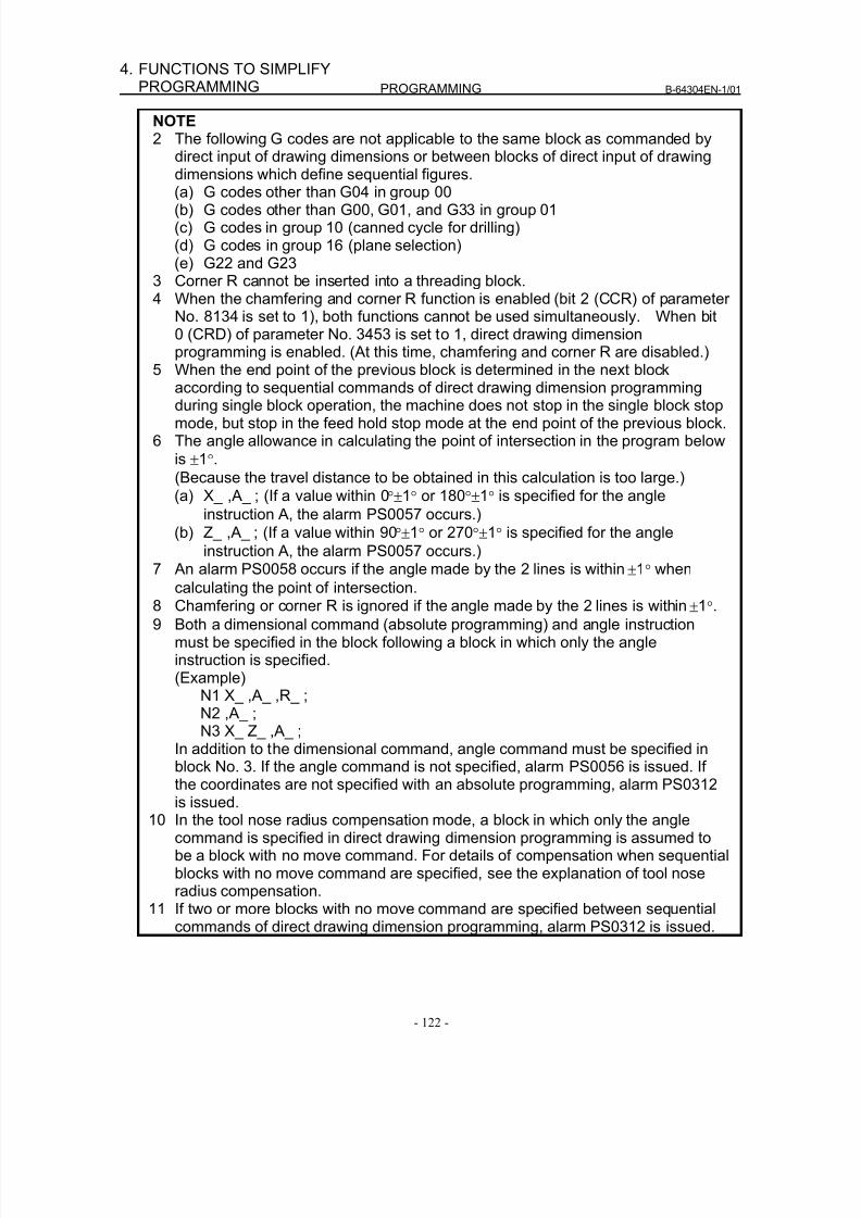
8/16/2019 Manual Operacion para FANUC
http://slidepdf.com/reader/full/manual-operacion-para-fanuc 140/435
PROGRAMMING B-64304EN-1/01
- 122 -
4. FUNCTIONS TO SIMPLIFYPROGRAMMING
NOTE2 The following G codes are not applicable to the same block as commanded by
direct input of drawing dimensions or between blocks of direct input of drawingdimensions which define sequential figures.
(a) G codes other than G04 in group 00(b) G codes other than G00, G01, and G33 in group 01(c) G codes in group 10 (canned cycle for drilling)(d) G codes in group 16 (plane selection)(e) G22 and G23
3 Corner R cannot be inserted into a threading block.4 When the chamfering and corner R function is enabled (bit 2 (CCR) of parameter
No. 8134 is set to 1), both functions cannot be used simultaneously. When bit0 (CRD) of parameter No. 3453 is set to 1, direct drawing dimensionprogramming is enabled. (At this time, chamfering and corner R are disabled.)
5 When the end point of the previous block is determined in the next block
according to sequential commands of direct drawing dimension programmingduring single block operation, the machine does not stop in the single block stopmode, but stop in the feed hold stop mode at the end point of the previous block.
6 The angle allowance in calculating the point of intersection in the program belowis ±1°.(Because the travel distance to be obtained in this calculation is too large.)(a) X_ ,A_ ; (If a value within 0°±1° or 180°±1° is specified for the angle
instruction A, the alarm PS0057 occurs.)(b) Z_ ,A_ ; (If a value within 90°±1° or 270°±1° is specified for the angle
instruction A, the alarm PS0057 occurs.)
7 An alarm PS0058 occurs if the angle made by the 2 lines is within ±1° whencalculating the point of intersection.
8 Chamfering or corner R is ignored if the angle made by the 2 lines is within ±1°.9 Both a dimensional command (absolute programming) and angle instruction
must be specified in the block following a block in which only the angleinstruction is specified.(Example)
N1 X_ ,A_ ,R_ ;N2 ,A_ ;N3 X_ Z_ ,A_ ;
In addition to the dimensional command, angle command must be specified in
block No. 3. If the angle command is not specified, alarm PS0056 is issued. Ifthe coordinates are not specified with an absolute programming, alarm PS0312is issued.
10 In the tool nose radius compensation mode, a block in which only the anglecommand is specified in direct drawing dimension programming is assumed tobe a block with no move command. For details of compensation when sequentialblocks with no move command are specified, see the explanation of tool noseradius compensation.
11 If two or more blocks with no move command are specified between sequentialcommands of direct drawing dimension programming, alarm PS0312 is issued.
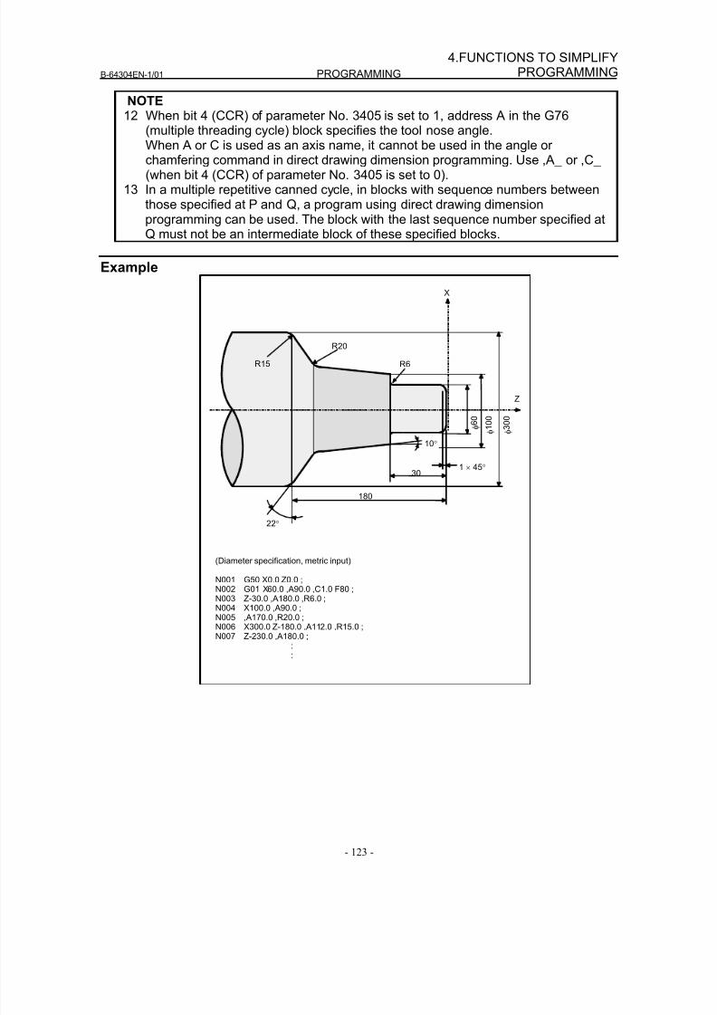
8/16/2019 Manual Operacion para FANUC
http://slidepdf.com/reader/full/manual-operacion-para-fanuc 141/435
B-64304EN-1/01 PROGRAMMING
- 123 -
4.FUNCTIONS TO SIMPLIFYPROGRAMMING
NOTE12 When bit 4 (CCR) of parameter No. 3405 is set to 1, address A in the G76
(multiple threading cycle) block specifies the tool nose angle.When A or C is used as an axis name, it cannot be used in the angle or
chamfering command in direct drawing dimension programming. Use ,A_ or ,C_(when bit 4 (CCR) of parameter No. 3405 is set to 0).
13 In a multiple repetitive canned cycle, in blocks with sequence numbers betweenthose specified at P and Q, a program using direct drawing dimensionprogramming can be used. The block with the last sequence number specified atQ must not be an intermediate block of these specified blocks.
Example
22°
180
301 × 45°
10°
R20
R6
X
φ 1 0 0
φ 3 0 0
Z
φ 6 0
(Diameter specification, metric input)
N001 G50 X0.0 Z0.0 ;N002 G01 X60.0 ,A90.0 ,C1.0 F80 ;N003 Z-30.0 ,A180.0 ,R6.0 ;N004 X100.0 ,A90.0 ;N005 ,A170.0 ,R20.0 ;N006 X300.0 Z-180.0 ,A112.0 ,R15.0 ;
N007 Z-230.0 ,A180.0 ;::
R15
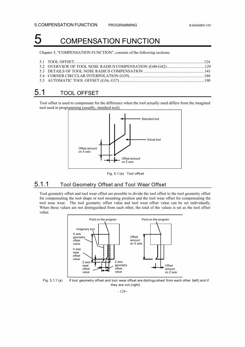
8/16/2019 Manual Operacion para FANUC
http://slidepdf.com/reader/full/manual-operacion-para-fanuc 142/435
5.COMPENSATION FUNCTION PROGRAMMING B-64304EN-1/01
- 124 -
5 COMPENSATION FUNCTION
Chapter 5, "COMPENSATION FUNCTION", consists of the following sections:
5.1 TOOL OFFSET.................................................................................................................................124
5.2 OVERVIEW OF TOOL NOSE RADIUS COMPENSATION (G40-G42)......................................129
5.3 DETAILS OF TOOL NOSE RADIUS COMPENSATION.............................................................141
5.4 CORNER CIRCULAR INTERPOLATION (G39) ..........................................................................188
5.5 AUTOMATIC TOOL OFFSET (G36, G37) ....................................................................................190
5.1 TOOL OFFSET
Tool offset is used to compensate for the difference when the tool actually used differs from the imagined
tool used in programming (usually, standard tool).
Offset amounton X axis
Standard tool
Actual tool
Offset amount
on Z axis
Fig. 5.1 (a) Tool offset
5.1.1 Tool Geometry Offset and Tool Wear Offset
Tool geometry offset and tool wear offset are possible to divide the tool offset to the tool geometry offset
for compensating the tool shape or tool mounting position and the tool wear offset for compensating the
tool nose wear. The tool geometry offset value and tool wear offset value can be set individually.
When these values are not distinguished from each other, the total of the values is set as the tool offset
value.
Point on the program
X axisgeometryoffsetvalue
X axiswear offsetvalue
Z axisgeometryoffset
value
Z axiswear offset
value
Offsetamounton X axis
Offsetamount
on Z axis
Point on the program
Imaginary tool
Fig. 5.1.1 (a) If tool geometry offset and tool wear offset are dist ingu ished from each other (left) and if
they are not (right)
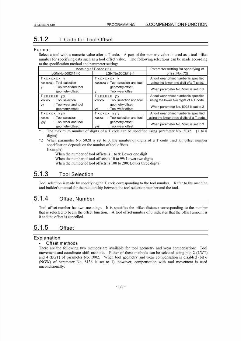
8/16/2019 Manual Operacion para FANUC
http://slidepdf.com/reader/full/manual-operacion-para-fanuc 143/435
B-64304EN-1/01 PROGRAMMING 5.COMPENSATION FUNCTION
- 125 -
5.1.2 T Code for Tool Offset
FormatSelect a tool with a numeric value after a T code. A part of the numeric value is used as a tool offsetnumber for specifying data such as a tool offset value. The following selections can be made according
to the specification method and parameter setting:
Meaning of T code (*1)
LGN(No.5002#1)=0 LGN(No.5002#1)=1
Parameter setting for specifying of
offset No. (*2)
A tool wear offset number is specified
using the lower one digit of a T code.
T x x x x x x x y
xxxxxxx : Tool selection
y : Tool wear and tool
geometry offset
T x x x x x x x y
xxxxxxx : Tool selection and tool
geometry offset
y : Tool wear offsetWhen parameter No. 5028 is set to 1
A tool wear offset number is specified
using the lower two digits of a T code.
T x x x x x x y y
xxxxxx : Tool selection
yy : Tool wear and tool
geometry offset
T x x x x x x y y
xxxxxx : Tool selection and tool
geometry offset
yy : Tool wear offset When parameter No. 5028 is set to 2
A tool wear offset number is specified
using the lower three digits of a T code.
T x x x x x y y y
xxxxx : Tool selection
yyy : Tool wear and tool
geometry offset
T x x x x x y y y
xxxxx : Tool selection and tool
geometry offset
yyy : Tool wear offsetWhen parameter No. 5028 is set to 3
*1 The maximum number of digits of a T code can be specified using parameter No. 3032. (1 to 8
digits)
*2 When parameter No. 5028 is set to 0, the number of digits of a T code used for offset number
specification depends on the number of tool offsets.
Example)
When the number of tool offsets is 1 to 9: Lower one digit
When the number of tool offsets is 10 to 99: Lower two digitsWhen the number of tool offsets is 100 to 200: Lower three digits
5.1.3 Tool Selection
Tool selection is made by specifying the T code corresponding to the tool number. Refer to the machine
tool builder's manual for the relationship between the tool selection number and the tool.
5.1.4 Offset Number
Tool offset number has two meanings. It is specifies the offset distance corresponding to the number
that is selected to begin the offset function. A tool offset number of 0 indicates that the offset amount is0 and the offset is cancelled.
5.1.5 Offset
Explanation- Offset methodsThere are the following two methods are available for tool geometry and wear compensation: Tool
movement and coordinate shift methods. Either of these methods can be selected using bits 2 (LWT)
and 4 (LGT) of parameter No. 5002. When tool geometry and wear compensation is disabled (bit 6
(NGW) of parameter No. 8136 is set to 1), however, compensation with tool movement is used
unconditionally.
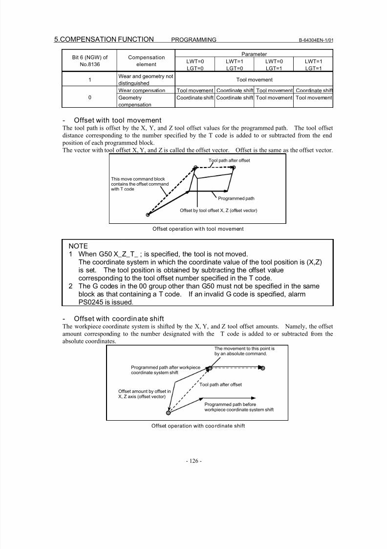
8/16/2019 Manual Operacion para FANUC
http://slidepdf.com/reader/full/manual-operacion-para-fanuc 144/435
5.COMPENSATION FUNCTION PROGRAMMING B-64304EN-1/01
- 126 -
ParameterBit 6 (NGW) of
No.8136
Compensation
elementLWT=0
LGT=0
LWT=1
LGT=0
LWT=0
LGT=1
LWT=1
LGT=1
1Wear and geometry not
distinguished
Tool movement
Wear compensation Tool movement Coordinate shift Tool movement Coordinate shift
0 Geometry
compensation
Coordinate shift Coordinate shift Tool movement Tool movement
- Offset with tool movementThe tool path is offset by the X, Y, and Z tool offset values for the programmed path. The tool offset
distance corresponding to the number specified by the T code is added to or subtracted from the end
position of each programmed block.
The vector with tool offset X, Y, and Z is called the offset vector. Offset is the same as the offset vector.
This move command blockcontains the offset commandwith T code
Tool path after offset
Programmed path
Offset by tool offset X, Z (offset vector)
Offset operation with tool movement
NOTE1 When G50 X_Z_T_ ; is specified, the tool is not moved.
The coordinate system in which the coordinate value of the tool position is (X,Z)is set. The tool position is obtained by subtracting the offset valuecorresponding to the tool offset number specified in the T code.
2 The G codes in the 00 group other than G50 must not be specified in the sameblock as that containing a T code. If an invalid G code is specified, alarmPS0245 is issued.
- Offset with coordinate shiftThe workpiece coordinate system is shifted by the X, Y, and Z tool offset amounts. Namely, the offset
amount corresponding to the number designated with the T code is added to or subtracted from the
absolute coordinates.
Programmed path after workpiececoordinate system shift
The movement to this point isby an absolute command.
Tool path after offset
Programmed path beforeworkpiece coordinate system shift
Offset amount by offset inX, Z axis (offset vector)
Offset operation with coordinate shift
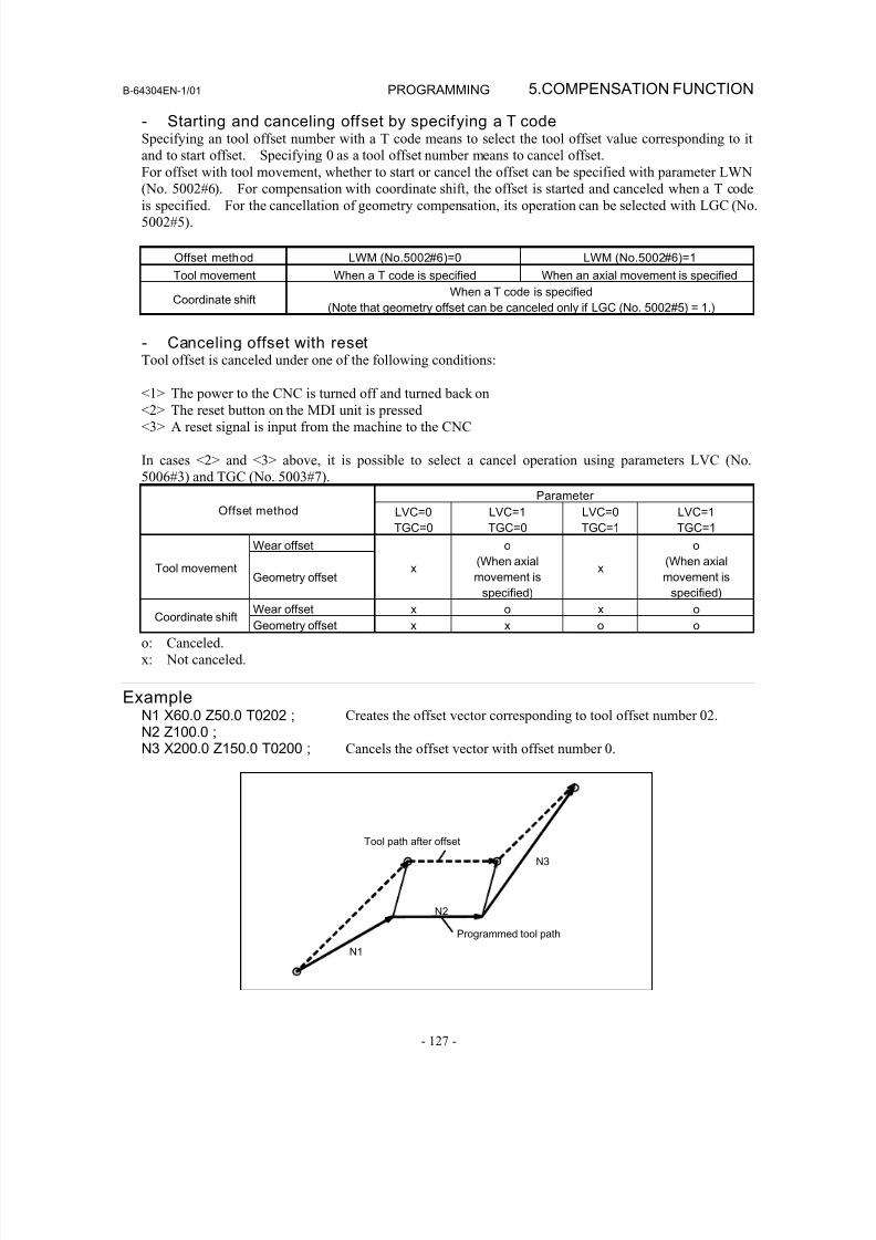
8/16/2019 Manual Operacion para FANUC
http://slidepdf.com/reader/full/manual-operacion-para-fanuc 145/435
B-64304EN-1/01 PROGRAMMING 5.COMPENSATION FUNCTION
- 127 -
- Starting and canceling offset by specifying a T codeSpecifying an tool offset number with a T code means to select the tool offset value corresponding to it
and to start offset. Specifying 0 as a tool offset number means to cancel offset.
For offset with tool movement, whether to start or cancel the offset can be specified with parameter LWN
(No. 5002#6). For compensation with coordinate shift, the offset is started and canceled when a T codeis specified. For the cancellation of geometry compensation, its operation can be selected with LGC (No.
5002#5).
Offset method LWM (No.5002#6)=0 LWM (No.5002#6)=1
Tool movement When a T code is specified When an axial movement is specified
Coordinate shiftWhen a T code is specified
(Note that geometry offset can be canceled only if LGC (No. 5002#5) = 1.)
- Canceling offset with resetTool offset is canceled under one of the following conditions:
<1> The power to the CNC is turned off and turned back on<2> The reset button on the MDI unit is pressed
<3> A reset signal is input from the machine to the CNC
In cases <2> and <3> above, it is possible to select a cancel operation using parameters LVC (No.
5006#3) and TGC (No. 5003#7).
Parameter
Offset method LVC=0
TGC=0
LVC=1
TGC=0
LVC=0
TGC=1
LVC=1
TGC=1
Wear offset
Tool movementGeometry offset
x
o
(When axial
movement is
specified)
x
o
(When axial
movement is
specified)
Wear offset x o x oCoordinate shift
Geometry offset x x o o
o: Canceled.
x: Not canceled.
ExampleN1 X60.0 Z50.0 T0202 ; Creates the offset vector corresponding to tool offset number 02.
N2 Z100.0 ;N3 X200.0 Z150.0 T0200 ; Cancels the offset vector with offset number 0.
N1
N2
Tool path after offset
Programmed tool path
N3
8/16/2019 Manual Operacion para FANUC
http://slidepdf.com/reader/full/manual-operacion-para-fanuc 146/435
5.COMPENSATION FUNCTION PROGRAMMING B-64304EN-1/01
- 128 -
Limitation- Helical interpolation (G02, G03)Tool offset cannot be specified in a block in which helical interpolation is used.
- Workpiece coordinate system preset (G50.3)Performing workpiece coordinate system preset causes tool offset with tool movement to be canceled; this
does not cause tool offset with coordinate shift to be canceled.
- Machine coordinate system setting (G53), reference posi tion return (G28),second, third, and fourth reference posit ion return (G30), and manualreference position return
Basically, before performing these commands or operations, cancel tool offset. These operations do not
cause tool offset to be canceled. The following actions take place:
When the command or operation is
specified
When the next axial movement command
is specifiedTool movement The tool offset value is temporarily
canceled.
The tool offset value is reflected.
Coordinate shift Coordinates with the tool offset value
reflected are assumed.
Coordinates with the tool offset value
reflected are assumed.
5.1.6 Y Axis Offset
OverviewWhen the Y axis, one of the basic three axes, is used with a lathe system, this function performs Y axis
offset.
When tool geometry and wear compensation is enabled (bit 6 (NGW) of parameter No. 8136 is set to 0),the compensation is also enabled for the Y axis offset.
ExplanationY axis offset results in the same operation as tool offset. For an explanation of the operation, related
parameters, and the like, refer to the item “Tool Offset.”
5.1.6.1 Y axis offset (arbi trary axes)
OverviewIn a lath system, Y axis offset has been usable with the basic three axes only. This function enables Y
axis offset to be used with arbitrary axes other than the Y axis, which is one of the basic three axes.Specify an axis number for which to use Y axis offset for parameter No. 5043.
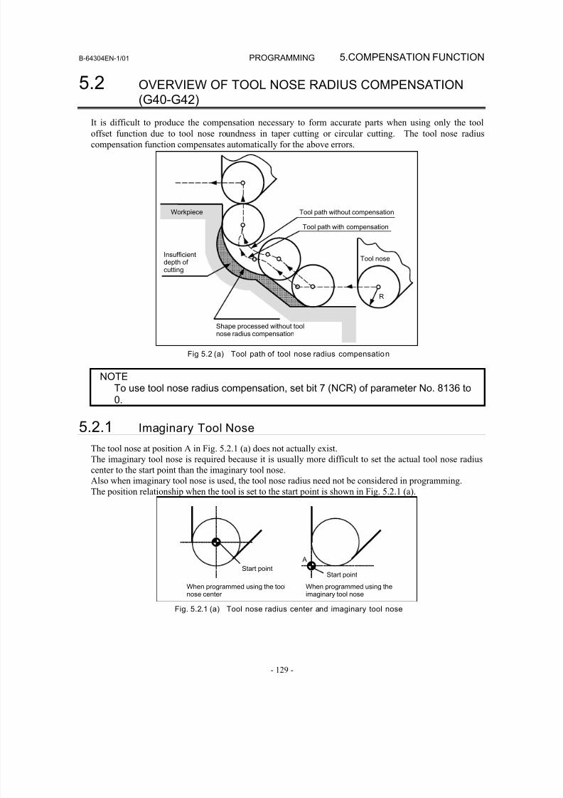
8/16/2019 Manual Operacion para FANUC
http://slidepdf.com/reader/full/manual-operacion-para-fanuc 147/435
B-64304EN-1/01 PROGRAMMING 5.COMPENSATION FUNCTION
- 129 -
5.2 OVERVIEW OF TOOL NOSE RADIUS COMPENSATION(G40-G42)
It is difficult to produce the compensation necessary to form accurate parts when using only the tooloffset function due to tool nose roundness in taper cutting or circular cutting. The tool nose radius
compensation function compensates automatically for the above errors.
R
Workpiece
Insufficientdepth of cutting
Shape processed without toolnose radius compensation
Tool path without compensation
Tool path with compensation
Tool nose
Fig 5.2 (a) Tool path of tool nose radius compensation
NOTETo use tool nose radius compensation, set bit 7 (NCR) of parameter No. 8136 to0.
5.2.1 Imaginary Tool Nose
The tool nose at position A in Fig. 5.2.1 (a) does not actually exist.
The imaginary tool nose is required because it is usually more difficult to set the actual tool nose radius
center to the start point than the imaginary tool nose.
Also when imaginary tool nose is used, the tool nose radius need not be considered in programming.
The position relationship when the tool is set to the start point is shown in Fig. 5.2.1 (a).
A
Start pointStart point
When programmed using the toolnose center
When programmed using theimaginary tool nose
Fig. 5.2.1 (a) Tool nose radius center and imaginary tool nose
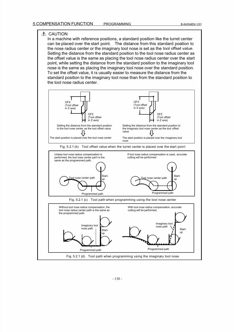
8/16/2019 Manual Operacion para FANUC
http://slidepdf.com/reader/full/manual-operacion-para-fanuc 148/435
5.COMPENSATION FUNCTION PROGRAMMING B-64304EN-1/01
- 130 -
CAUTIONIn a machine with reference positions, a standard position like the turret centercan be placed over the start point. The distance from this standard position tothe nose radius center or the imaginary tool nose is set as the tool offset value.
Setting the distance from the standard position to the tool nose radius center asthe offset value is the same as placing the tool nose radius center over the startpoint, while setting the distance from the standard position to the imaginary toolnose is the same as placing the imaginary tool nose over the standard position.To set the offset value, it is usually easier to measure the distance from thestandard position to the imaginary tool nose than from the standard position tothe tool nose radius center.
OFX(Tool offsetin X axis)
OFZ(Tool offsetin Z axis)
Setting the distance from the standard positionto the tool nose center as the tool offset value
Setting the distance from the standard position tothe imaginary tool nose center as the tool offsetvalue
The start position is placed over the tool nose center The start position is placed over the imaginary toolnose
OFX
(Tool offsetin X axis)
OFZ(Tool offsetin Z axis)
Fig. 5.2.1 (b) Tool offset value when the turret center is placed over the start point
Unless tool nose radius compensation isperformed, the tool nose center path is thesame as the programmed path.
If tool nose radius compensation is used, accuratecutting will be performed.
Tool nose center path
Programmed path
Start-up
Start-up
Programmed path
Tool nose center path
Fig. 5.2.1 (c) Tool path when programming using the tool nose center
Without tool nose radius compensation, thetool nose radius center path is the same asthe programmed path.
With tool nose radius compensation, accuratecutting will be performed.
Imaginary toolnose path
Imaginary toolnose path
Start-up
Start-up
Programmed path Programmed path
Fig. 5.2.1 (d) Tool path when programming using the imaginary tool nose
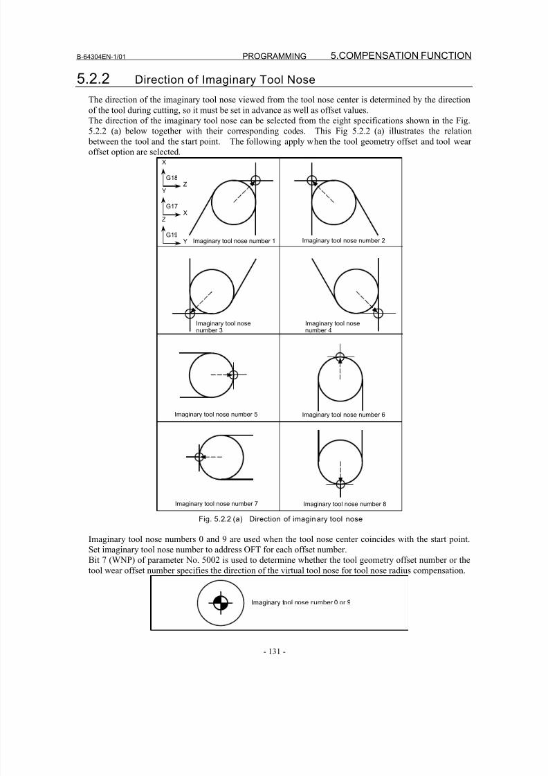
8/16/2019 Manual Operacion para FANUC
http://slidepdf.com/reader/full/manual-operacion-para-fanuc 149/435
B-64304EN-1/01 PROGRAMMING 5.COMPENSATION FUNCTION
- 131 -
5.2.2 Direction of Imaginary Tool Nose
The direction of the imaginary tool nose viewed from the tool nose center is determined by the direction
of the tool during cutting, so it must be set in advance as well as offset values.
The direction of the imaginary tool nose can be selected from the eight specifications shown in the Fig.5.2.2 (a) below together with their corresponding codes. This Fig 5.2.2 (a) illustrates the relation
between the tool and the start point. The following apply when the tool geometry offset and tool wear
offset option are selected.
Imaginary tool nose number 1 Imaginary tool nose number 2
Imaginary tool nosenumber 3
Imaginary tool nosenumber 4
Imaginary tool nose number 5 Imaginary tool nose number 6
Imaginary tool nose number 7 Imaginary tool nose number 8
X
ZG18
Y
XG17
Z
Y
G19
Fig. 5.2.2 (a) Direction of imaginary tool nose
Imaginary tool nose numbers 0 and 9 are used when the tool nose center coincides with the start point.
Set imaginary tool nose number to address OFT for each offset number.
Bit 7 (WNP) of parameter No. 5002 is used to determine whether the tool geometry offset number or the
tool wear offset number specifies the direction of the virtual tool nose for tool nose radius compensation.
Imaginary tool nose number 0 or 9
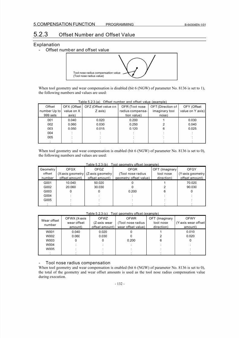
8/16/2019 Manual Operacion para FANUC
http://slidepdf.com/reader/full/manual-operacion-para-fanuc 150/435
5.COMPENSATION FUNCTION PROGRAMMING B-64304EN-1/01
- 132 -
5.2.3 Offset Number and Offset Value
Explanation- Offset number and offset value
Tool nose radius compensation value(Tool nose radius value)
When tool geometry and wear compensation is disabled (bit 6 (NGW) of parameter No. 8136 is set to 1),
the following numbers and values are used:
Table 5.2.3 (a) Offset number and offset value (example)
Offsetnumber Up to
999 sets
OFX (Offsetvalue on X
axis)
OFZ (Offset value onZ axis)
OFR (Tool noseradius compensa-
tion value)
OFT (Direction o fimaginary tool
nose)
OFY (Offsetvalue on Y axis)
001
002
003
004
005
:
0.040
0.060
0.050
:
:
:
0.020
0.030
0.015
:
:
:
0.200
0.250
0.120
:
:
:
1
2
6
:
:
:
0.030
0.040
0.025
:
:
:
When tool geometry and wear compensation is enabled (bit 6 (NGW) of parameter No. 8136 is set to 0),
the following numbers and values are used:
Table 5.2.3 (b) Tool geometry offset (example)
Geometry
offset
number
OFGX
(X-axis geometry
offset amount)
OFGZ
(Z-axis geometry
offset amount)
OFGR
(Tool nose radius
geometry offset value)
OFT (Imaginary
tool nose
direction)
OFGY
(Y-axis geometry
offset amount)
G001
G002
G003
G004
G005
:
10.040
20.060
0
:
:
:
50.020
30.030
0
:
:
:
0
0
0.200
:
:
:
1
2
6
:
:
:
70.020
90.030
0
:
:
:
Table 5.2.3 (c) Tool geometry offset (example)
Wear offset
number
OFWX (X-axis
wear offset
amount)
OFWZ
(Z-axis wear
offset amount)
OFWR
(Tool nose radius
wear offset value)
OFT (Imaginary
tool nose
direction)
OFWY
(Y-axis wear off set
amount)
W001
W002
W003
W004
W005
:
0.040
0.060
0
:
:
:
0.020
0.030
0
:
:
:
0
0
0.200
:
:
:
1
2
6
:
:
:
0.010
0.020
0
:
:
:
- Tool nose radius compensationWhen tool geometry and wear compensation is enabled (bit 6 (NGW) of parameter No. 8136 is set to 0),
the total of the geometry and wear offset amounts is used as the tool nose radius compensation value
during execution.
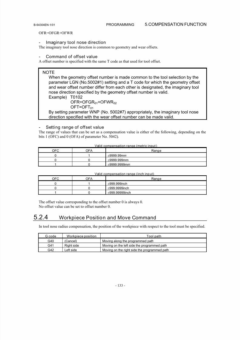
8/16/2019 Manual Operacion para FANUC
http://slidepdf.com/reader/full/manual-operacion-para-fanuc 151/435
B-64304EN-1/01 PROGRAMMING 5.COMPENSATION FUNCTION
- 133 -
OFR=OFGR+OFWR
- Imaginary tool nose directionThe imaginary tool nose direction is common to geometry and wear offsets.
- Command of offset valueA offset number is specified with the same T code as that used for tool offset.
NOTEWhen the geometry offset number is made common to the tool selection by theparameter LGN (No.5002#1) setting and a T code for which the geometry offsetand wear offset number differ from each other is designated, the imaginary toolnose direction specified by the geometry offset number is valid.Example) T0102
OFR=OFGR01+OFWR02
OFT=OFT01
By setting parameter WNP (No. 5002#7) appropriately, the imaginary tool nosedirection specified with the wear offset number can be made valid.
- Setting range of offset valueThe range of values that can be set as a compensation value is either of the following, depending on the
bits 1 (OFC) and 0 (OFA) of parameter No. 5042).
Valid compensation range (metric input )
OFC OFA Range
0 1 ±9999.99mm
0 0 ±9999.999mm1 0 ±9999.9999mm
Valid compensation range (inch input)
OFC OFA Range
0 1 ±999.999inch
0 0 ±999.9999inch
1 0 ±999.99999inch
The offset value corresponding to the offset number 0 is always 0.
No offset value can be set to offset number 0.
5.2.4 Workpiece Position and Move Command
In tool nose radius compensation, the position of the workpiece with respect to the tool must be specified.
G code Workpiece position Tool path
G40 (Cancel) Moving along the programmed path
G41 Right side Moving on the left side the programmed path
G42 Left side Moving on the right side the programmed path
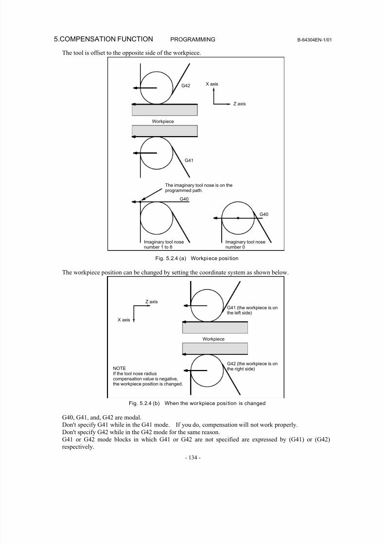
8/16/2019 Manual Operacion para FANUC
http://slidepdf.com/reader/full/manual-operacion-para-fanuc 152/435
5.COMPENSATION FUNCTION PROGRAMMING B-64304EN-1/01
- 134 -
The tool is offset to the opposite side of the workpiece.
Workpiece
G41
G42 X axis
Z axis
G40
G40
The imaginary tool nose is on theprogrammed path.
Imaginary tool nosenumber 1 to 8
Imaginary tool nosenumber 0
Fig. 5.2.4 (a) Workpiece posi tion
The workpiece position can be changed by setting the coordinate system as shown below.
Workpiece
X axis
Z axis
G41 (the workpiece is onthe left side)
G42 (the workpiece is onthe right side)NOTE
If the tool nose radiuscompensation value is negative,the workpiece position is changed.
Fig. 5.2.4 (b) When the workpiece posi tion is changed
G40, G41, and, G42 are modal.
Don't specify G41 while in the G41 mode. If you do, compensation will not work properly.
Don't specify G42 while in the G42 mode for the same reason.
G41 or G42 mode blocks in which G41 or G42 are not specified are expressed by (G41) or (G42)
respectively.
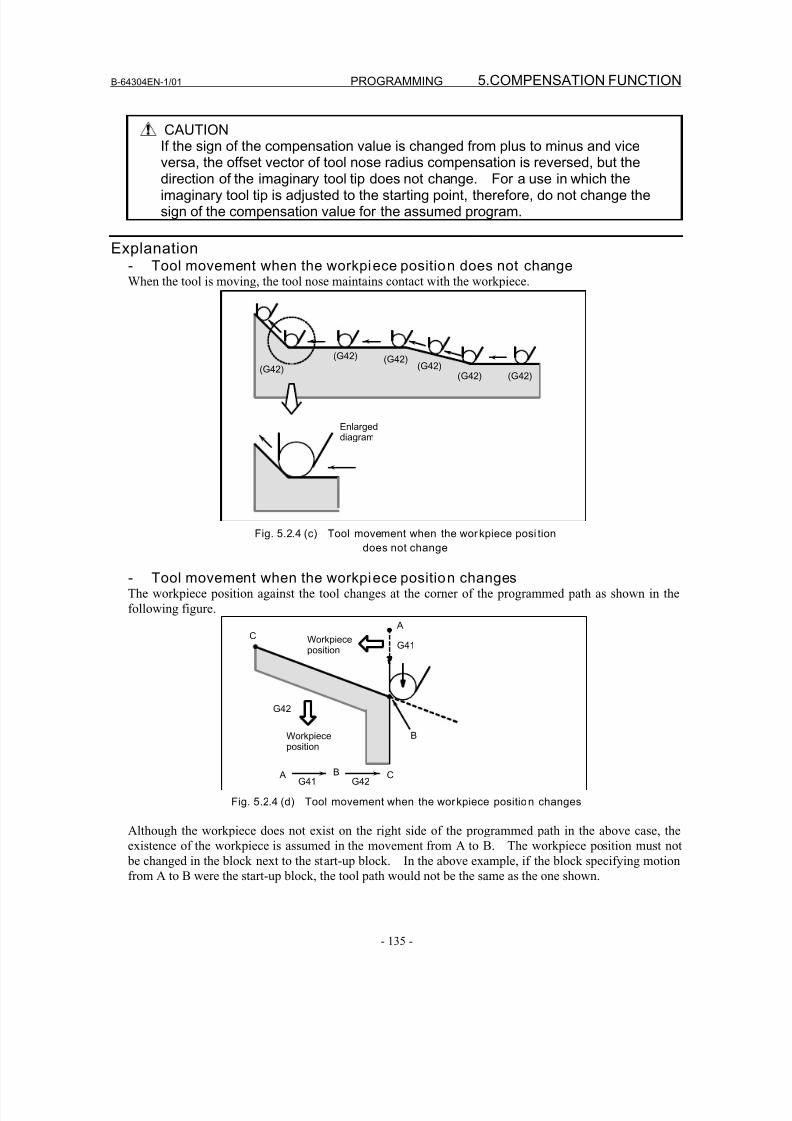
8/16/2019 Manual Operacion para FANUC
http://slidepdf.com/reader/full/manual-operacion-para-fanuc 153/435
B-64304EN-1/01 PROGRAMMING 5.COMPENSATION FUNCTION
- 135 -
CAUTIONIf the sign of the compensation value is changed from plus to minus and viceversa, the offset vector of tool nose radius compensation is reversed, but the
direction of the imaginary tool tip does not change. For a use in which theimaginary tool tip is adjusted to the starting point, therefore, do not change thesign of the compensation value for the assumed program.
Explanation- Tool movement when the workpiece position does not changeWhen the tool is moving, the tool nose maintains contact with the workpiece.
(G42)
(G42) (G42)(G42)
(G42) (G42)
Enlargeddiagram
Fig. 5.2.4 (c) Tool movement when the workpiece posi tion
does not change
- Tool movement when the workpiece position changesThe workpiece position against the tool changes at the corner of the programmed path as shown in the
following figure.
Workpieceposition
Workpieceposition
G42
G42G41
G41
A
A B C
B
C
Fig. 5.2.4 (d) Tool movement when the workpiece position changes
Although the workpiece does not exist on the right side of the programmed path in the above case, the
existence of the workpiece is assumed in the movement from A to B. The workpiece position must not
be changed in the block next to the start-up block. In the above example, if the block specifying motion
from A to B were the start-up block, the tool path would not be the same as the one shown.
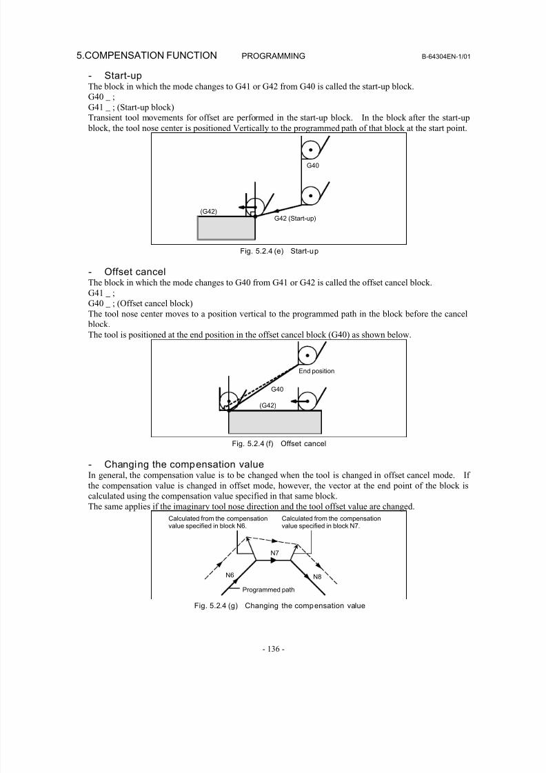
8/16/2019 Manual Operacion para FANUC
http://slidepdf.com/reader/full/manual-operacion-para-fanuc 154/435
5.COMPENSATION FUNCTION PROGRAMMING B-64304EN-1/01
- 136 -
- Start-upThe block in which the mode changes to G41 or G42 from G40 is called the start-up block.
G40 _ ;
G41 _ ; (Start-up block)
Transient tool movements for offset are performed in the start-up block. In the block after the start-up block, the tool nose center is positioned Vertically to the programmed path of that block at the start point.
G40
(G42)G42 (Start-up)
Fig. 5.2.4 (e) Start-up
- Offset cancelThe block in which the mode changes to G40 from G41 or G42 is called the offset cancel block.
G41 _ ;
G40 _ ; (Offset cancel block)
The tool nose center moves to a position vertical to the programmed path in the block before the cancel
block.
The tool is positioned at the end position in the offset cancel block (G40) as shown below.
G40
(G42)
End position
Fig. 5.2.4 (f) Offset cancel
- Changing the compensation valueIn general, the compensation value is to be changed when the tool is changed in offset cancel mode. If
the compensation value is changed in offset mode, however, the vector at the end point of the block iscalculated using the compensation value specified in that same block.
The same applies if the imaginary tool nose direction and the tool offset value are changed.
Calculated from the compensationvalue specified in block N6.
Calculated from the compensationvalue specified in block N7.
N8N6
N7
Programmed path
Fig. 5.2.4 (g) Changing the compensation value

8/16/2019 Manual Operacion para FANUC
http://slidepdf.com/reader/full/manual-operacion-para-fanuc 155/435
B-64304EN-1/01 PROGRAMMING 5.COMPENSATION FUNCTION
- 137 -
- Specif ication of G41/G42 in G41/G42 modeWhen a G41 or G42 code is specified again in G41/G42 mode, the tool nose center is positioned vertical
to the programmed path of the preceding block at the end position of the preceding block.
G42(G42)
(G42)
G42 W-500.0 U-500.0 ;
Fig. 5.2.4 (h) Specif icat ion of G41/G42 in G41/G42 mode
In the block that first changes from G40 to G41/G42, the above positioning of the tool nose center is not
performed.
- Tool movement when the moving direction of the tool in a block whichincludes a G40 (offset cancel) command is different from the direction of theworkpiece
When you wish to retract the tool in the direction specified by X(U) and Z(W) canceling the tool nose
radius compensation at the end of machining the first block in the figure below, specify the following :
G40 X(U) _ Z(W) _ I _ K _ ;
where I and K are the direction of the workpiece in the next block, which is specified in incremental
mode.
(G42)
G40 U_ W_ I_ K_ ;
G40
I, K
U, WMoving direction of tool
Fig. 5.2.4 (i) If I and K are specified in the same block as G40
Thus, this prevents the tool from overcutting, as shown in Fig. 5.2.4 (j).
G40 U_ W_ ;
(G42)
G40
U,W Actual move command
Fig. 5.2.4 (j) Case in which overcutting occurs in the same block as G40
The workpiece position specified by addresses I and K is the same as that in the preceding block.
Specify I_K_; in the same block as G40. If it is specified in the same block as G02 or G03, it is assumed
to be the center of the arc.
G40 X_ Z_ I_ K_ ; Tool nose radius compensation
G02 X_ Z_ I_ K_ ; Circular interpolation
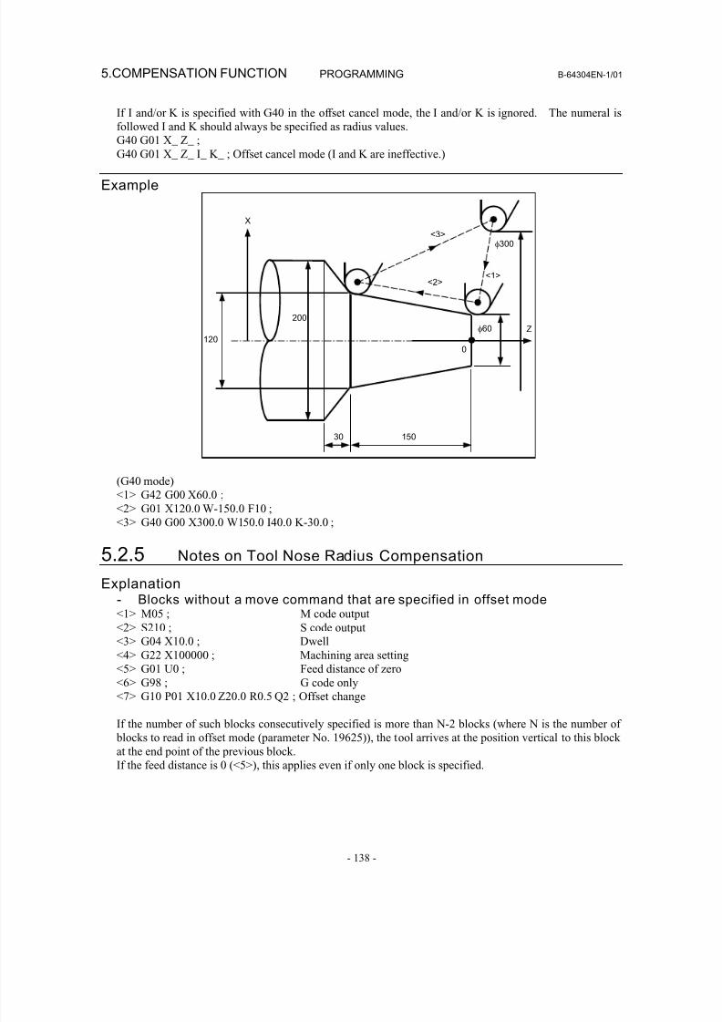
8/16/2019 Manual Operacion para FANUC
http://slidepdf.com/reader/full/manual-operacion-para-fanuc 156/435
5.COMPENSATION FUNCTION PROGRAMMING B-64304EN-1/01
- 138 -
If I and/or K is specified with G40 in the offset cancel mode, the I and/or K is ignored. The numeral is
followed I and K should always be specified as radius values.
G40 G01 X_ Z_ ;
G40 G01 X_ Z_ I_ K_ ; Offset cancel mode (I and K are ineffective.)
Example
X
Z120
200
30 150
φ60
φ300
<1><2>
<3>
0
(G40 mode)<1> G42 G00 X60.0 ;
<2> G01 X120.0 W-150.0 F10 ;
<3> G40 G00 X300.0 W150.0 I40.0 K-30.0 ;
5.2.5 Notes on Tool Nose Radius Compensation
Explanation- Blocks without a move command that are specified in offset mode<1> M05 ; M code output
<2> S210 ; S code output
<3> G04 X10.0 ; Dwell<4> G22 X100000 ; Machining area setting
<5> G01 U0 ; Feed distance of zero
<6> G98 ; G code only
<7> G10 P01 X10.0 Z20.0 R0.5 Q2 ; Offset change
If the number of such blocks consecutively specified is more than N-2 blocks (where N is the number of
blocks to read in offset mode (parameter No. 19625)), the tool arrives at the position vertical to this block
at the end point of the previous block.
If the feed distance is 0 (<5>), this applies even if only one block is specified.
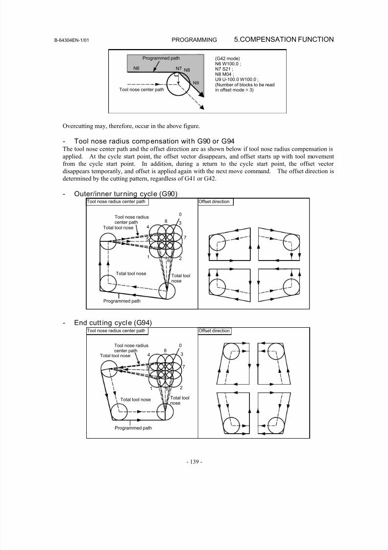
8/16/2019 Manual Operacion para FANUC
http://slidepdf.com/reader/full/manual-operacion-para-fanuc 157/435
B-64304EN-1/01 PROGRAMMING 5.COMPENSATION FUNCTION
- 139 -
(G42 mode)N6 W100.0 ;N7 S21 ;N8 M04 ;U9 U-100.0 W100.0 ;
(Number of blocks to be readin offset mode = 3)
N6 N7 N8
N9
Tool nose center path
Programmed path
Overcutting may, therefore, occur in the above figure.
- Tool nose radius compensation with G90 or G94The tool nose center path and the offset direction are as shown below if tool nose radius compensation is
applied. At the cycle start point, the offset vector disappears, and offset starts up with tool movement
from the cycle start point. In addition, during a return to the cycle start point, the offset vector
disappears temporarily, and offset is applied again with the next move command. The offset direction isdetermined by the cutting pattern, regardless of G41 or G42.
- Outer/inner turning cycle (G90)Tool nose radius center path Offset direction
Total tool nose
Tool nose radiuscenter path
Programmed path
0
84
5 7
3
1 6 2
Total toolnose
Total tool nose
- End cutt ing cycle (G94)
Total tool nose
Tool nose radiuscenter path
Programmed path
08
4
5 7
3
1 6 2
Total toolnose
Total tool nose
Tool nose radius center path Offset direction
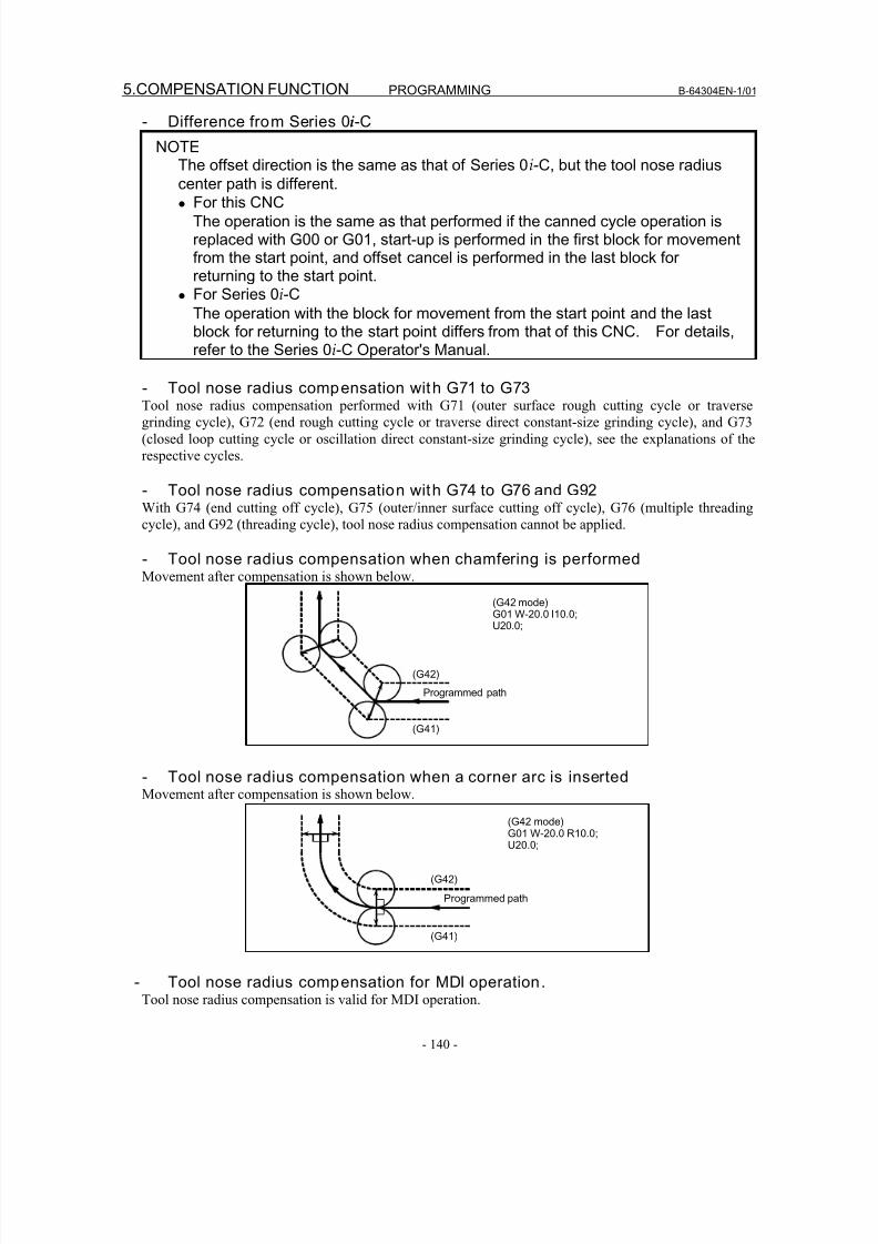
8/16/2019 Manual Operacion para FANUC
http://slidepdf.com/reader/full/manual-operacion-para-fanuc 158/435
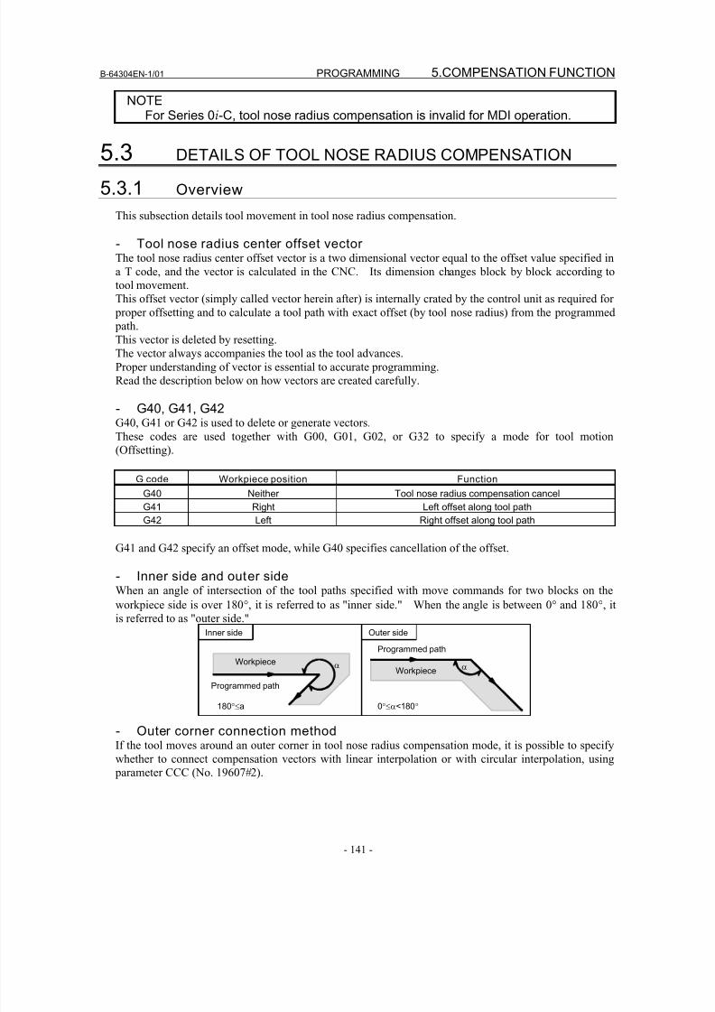
8/16/2019 Manual Operacion para FANUC
http://slidepdf.com/reader/full/manual-operacion-para-fanuc 159/435
B-64304EN-1/01 PROGRAMMING 5.COMPENSATION FUNCTION
- 141 -
NOTEFor Series 0i-C, tool nose radius compensation is invalid for MDI operation.
5.3 DETAILS OF TOOL NOSE RADIUS COMPENSATION
5.3.1 Overview
This subsection details tool movement in tool nose radius compensation.
- Tool nose radius center offset vectorThe tool nose radius center offset vector is a two dimensional vector equal to the offset value specified in
a T code, and the vector is calculated in the CNC. Its dimension changes block by block according to
tool movement.
This offset vector (simply called vector herein after) is internally crated by the control unit as required for
proper offsetting and to calculate a tool path with exact offset (by tool nose radius) from the programmed path.
This vector is deleted by resetting.
The vector always accompanies the tool as the tool advances.
Proper understanding of vector is essential to accurate programming.
Read the description below on how vectors are created carefully.
- G40, G41, G42G40, G41 or G42 is used to delete or generate vectors.
These codes are used together with G00, G01, G02, or G32 to specify a mode for tool motion
(Offsetting).
G code Workpiece position Function
G40 Neither Tool nose radius compensation cancel
G41 Right Left offset along tool path
G42 Left Right offset along tool path
G41 and G42 specify an offset mode, while G40 specifies cancellation of the offset.
- Inner side and outer sideWhen an angle of intersection of the tool paths specified with move commands for two blocks on the
workpiece side is over 180°, it is referred to as "inner side." When the angle is between 0° and 180°, it
is referred to as "outer side."
αWorkpieceα
Programmed pathInner side
180°≤a 0°≤α<180°
Outer side
Workpiece
Programmed path
- Outer corner connection methodIf the tool moves around an outer corner in tool nose radius compensation mode, it is possible to specify
whether to connect compensation vectors with linear interpolation or with circular interpolation, using
parameter CCC (No. 19607#2).
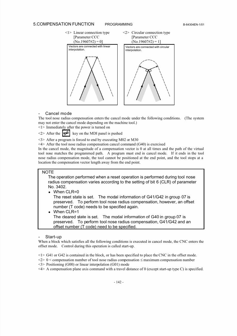
8/16/2019 Manual Operacion para FANUC
http://slidepdf.com/reader/full/manual-operacion-para-fanuc 160/435
5.COMPENSATION FUNCTION PROGRAMMING B-64304EN-1/01
- 142 -
<1> Linear connection type
[Parameter CCC
(No.19607#2) = 0]
<2> Circular connection type
[Parameter CCC
(No.19607#2) = 1]
Vectors are connected with linear interpolation.
Vectors are connected with circular interpolation.
- Cancel modeThe tool nose radius compensation enters the cancel mode under the following conditions. (The system
may not enter the cancel mode depending on the machine tool.)
<1> Immediately after the power is turned on
<2> After the key on the MDI panel is pushed
<3> After a program is forced to end by executing M02 or M30
<4> After the tool nose radius compensation cancel command (G40) is exercised
In the cancel mode, the magnitude of a compensation vector is 0 at all times and the path of the virtual
tool nose matches the programmed path. A program must end in cancel mode. If it ends in the tool
nose radius compensation mode, the tool cannot be positioned at the end point, and the tool stops at alocation the compensation vector length away from the end point.
NOTEThe operation performed when a reset operation is performed during tool noseradius compensation varies according to the setting of bit 6 (CLR) of parameterNo. 3402.• When CLR=0
The reset state is set. The modal information of G41/G42 in group 07 ispreserved. To perform tool nose radius compensation, however, an offsetnumber (T code) needs to be specified again.
• When CLR=1The cleared state is set. The modal information of G40 in group 07 ispreserved. To perform tool nose radius compensation, G41/G42 and anoffset number (T code) need to be specified.
- Start-upWhen a block which satisfies all the following conditions is executed in cancel mode, the CNC enters the
offset mode. Control during this operation is called start-up.
<1> G41 or G42 is contained in the block, or has been specified to place the CNC in the offset mode.
<2> 0 < compensation number of tool nose radius compensation ≤ maximum compensation number
<3> Positioning (G00) or linear interpolation (G01) mode<4> A compensation plane axis command with a travel distance of 0 (except start-up type C) is specified.
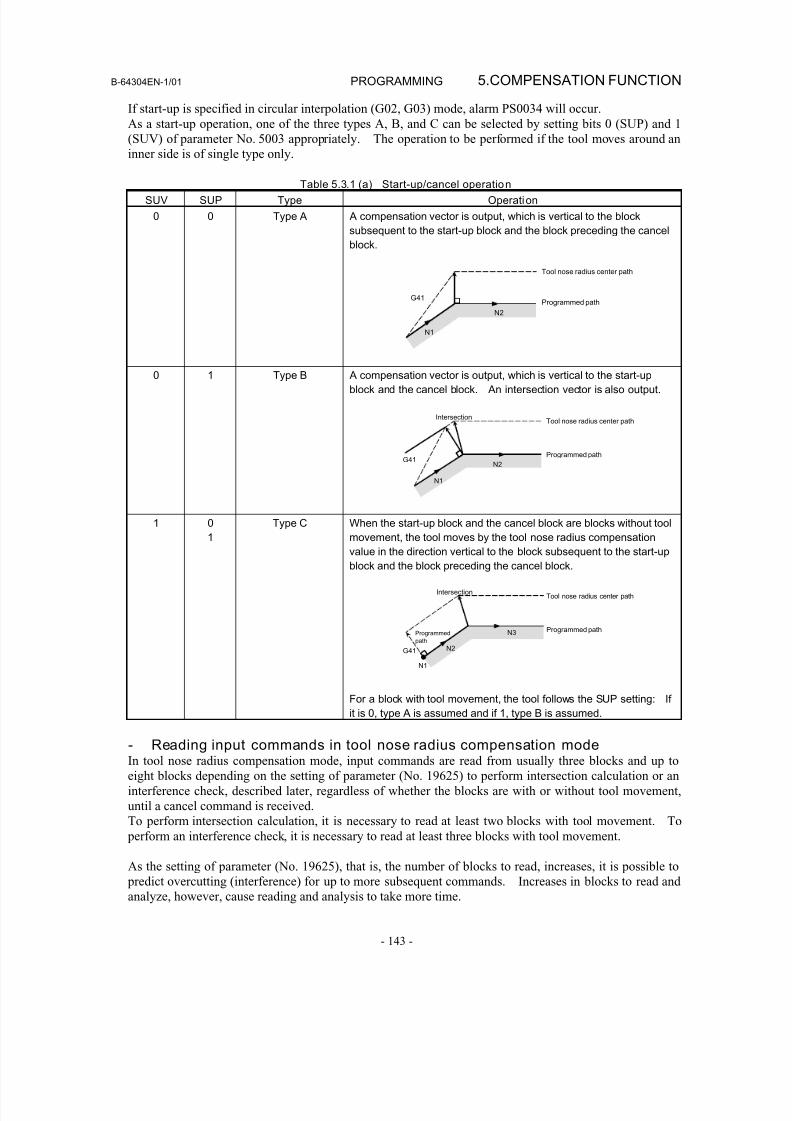
8/16/2019 Manual Operacion para FANUC
http://slidepdf.com/reader/full/manual-operacion-para-fanuc 161/435
B-64304EN-1/01 PROGRAMMING 5.COMPENSATION FUNCTION
- 143 -
If start-up is specified in circular interpolation (G02, G03) mode, alarm PS0034 will occur.
As a start-up operation, one of the three types A, B, and C can be selected by setting bits 0 (SUP) and 1
(SUV) of parameter No. 5003 appropriately. The operation to be performed if the tool moves around an
inner side is of single type only.
Table 5.3.1 (a) Start-up/cancel operation
SUV SUP Type Operation
0 0 Type A A compensation vector is output, which is vertical to the block
subsequent to the start-up block and the block preceding the cancel
block.
G41
N1
N2
Tool nose radius center path
Programmed path
0 1 Type B A compensation vector is output, which is vertical to the start-up
block and the cancel block. An intersection vector is also output.
G41
N1
N2
IntersectionTool nose radius center path
Programmed path
1 01 Type C When the start-up block and the cancel block are blocks without toolmovement, the tool moves by the tool nose radius compensation
value in the direction vertical to the block subsequent to the start-up
block and the block preceding the cancel block.
G41
N1
N2
IntersectionTool nose radius center path
Programmed pathN3Programmed
path
For a block with tool movement, the tool follows the SUP setting: Ifit is 0, type A is assumed and if 1, type B is assumed.
- Reading input commands in tool nose radius compensation modeIn tool nose radius compensation mode, input commands are read from usually three blocks and up to
eight blocks depending on the setting of parameter (No. 19625) to perform intersection calculation or an
interference check, described later, regardless of whether the blocks are with or without tool movement,
until a cancel command is received.
To perform intersection calculation, it is necessary to read at least two blocks with tool movement. To
perform an interference check, it is necessary to read at least three blocks with tool movement.
As the setting of parameter (No. 19625), that is, the number of blocks to read, increases, it is possible to
predict overcutting (interference) for up to more subsequent commands. Increases in blocks to read andanalyze, however, cause reading and analysis to take more time.
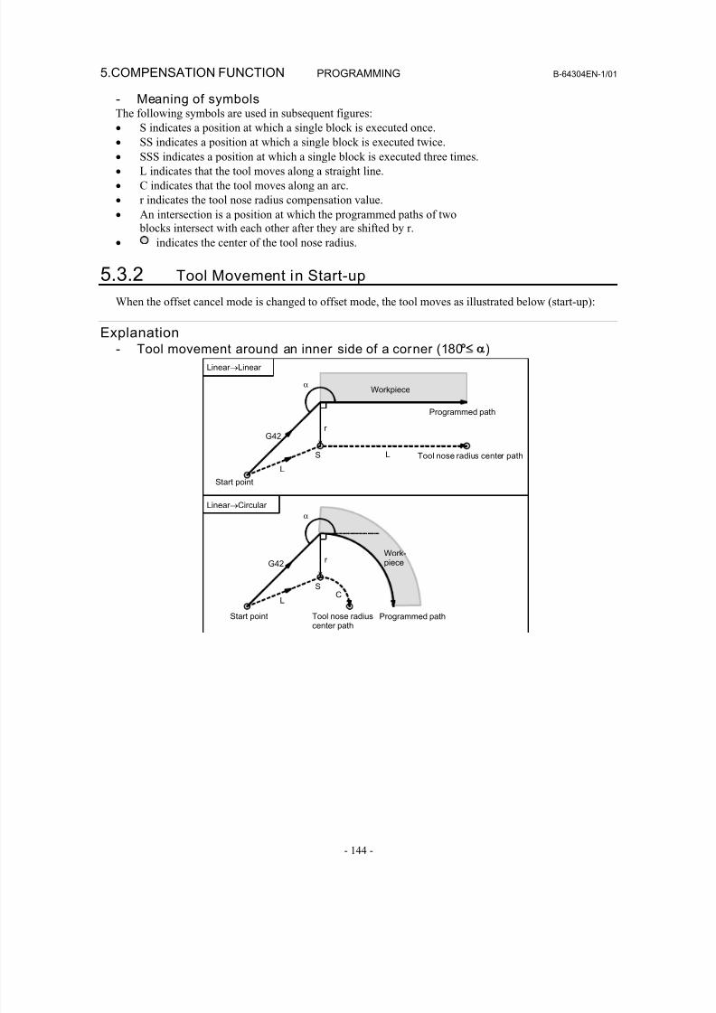
8/16/2019 Manual Operacion para FANUC
http://slidepdf.com/reader/full/manual-operacion-para-fanuc 162/435
5.COMPENSATION FUNCTION PROGRAMMING B-64304EN-1/01
- 144 -
- Meaning of symbolsThe following symbols are used in subsequent figures:
• S indicates a position at which a single block is executed once.
• SS indicates a position at which a single block is executed twice.
• SSS indicates a position at which a single block is executed three times.• L indicates that the tool moves along a straight line.
• C indicates that the tool moves along an arc.
• r indicates the tool nose radius compensation value.
• An intersection is a position at which the programmed paths of two
blocks intersect with each other after they are shifted by r.
• indicates the center of the tool nose radius.
5.3.2 Tool Movement in Start-up
When the offset cancel mode is changed to offset mode, the tool moves as illustrated below (start-up):
Explanation- Tool movement around an inner side of a corner (180° )
α
LS
G42r
L
α
S
r
LC
G42
Tool nose radiuscenter path
Start point
Programmed path
Work-piece
Linear →Circular
Start point
Workpiece
Tool nose radius center path
Linear →Linear
Programmed path
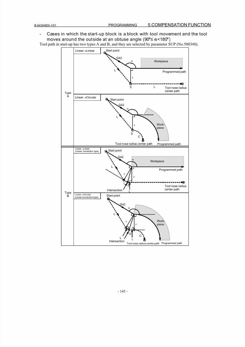
8/16/2019 Manual Operacion para FANUC
http://slidepdf.com/reader/full/manual-operacion-para-fanuc 163/435
B-64304EN-1/01 PROGRAMMING 5.COMPENSATION FUNCTION
- 145 -
- Cases in which the start-up block is a block with tool movement and the tool
moves around the outside at an obtuse angle (90° <180°)Tool path in start-up has two types A and B, and they are selected by parameter SUP (No.5003#0).
Linear →Linear
α
Programmed path
Tool nose radiuscenter path
LS
G42
r
L
Linear →Circular
r
Type A
TypeB
α
LS
G42
L
Workpiece
Start point
r
L
Linear →Linear (Linear connection type)
Linear →Circular (Linear connection type)
Workpiece
Start point
Start point
Work-piece
Programmed path
Tool nose radiuscenter path
Tool nose radius center path
Intersection
Intersection
Workpiece
Programmed path
Start point
C
G42
L
r
S
α
Tool nose radius center path
L
L
α
SC
G42
r
L
r
Programmed path
Work-piece
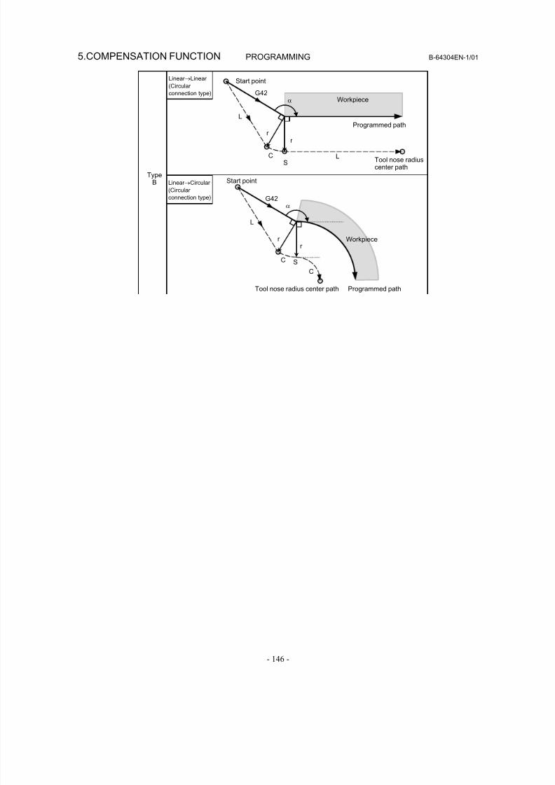
8/16/2019 Manual Operacion para FANUC
http://slidepdf.com/reader/full/manual-operacion-para-fanuc 164/435
5.COMPENSATION FUNCTION PROGRAMMING B-64304EN-1/01
- 146 -
TypeB
Linear →Linear
(Circular
connection type)
Linear →Circular
(Circular
connection type)
Programmed pathTool nose radius center path
Start point
L
α
S
C
G42
Workpiecer
r
r
α
Programmed path
Tool nose radiuscenter path
LS
G42
L
Workpiece
Start point
r
C
C
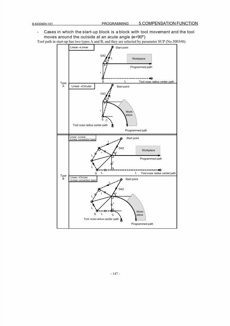
8/16/2019 Manual Operacion para FANUC
http://slidepdf.com/reader/full/manual-operacion-para-fanuc 165/435
B-64304EN-1/01 PROGRAMMING 5.COMPENSATION FUNCTION
- 147 -
- Cases in which the start-up block is a block with tool movement and the tool
moves around the outside at an acute angle ( <90°)Tool path in start-up has two types A and B, and they are selected by parameter SUP (No.5003#0).
α
LS
G42
r
L
S C
Type A
TypeB
r
G42L
G42
L
L L
L
S
r
r
G42
L
L
L
S
r
r
C
L
L
Linear →Linear
Linear →Circular
Linear →Linear (Linear connection type)
Linear →Circular (Linear connection type)
Workpiece
Work-piece
Workpiece
Work-piece
Start point
Start point
Start point
Start point
Programmed path
Programmed path
Programmed path
Programmed path
Tool nose radius center path
Tool nose radius center path
Tool nose radius center path
α
α
α
Tool nose radius center path
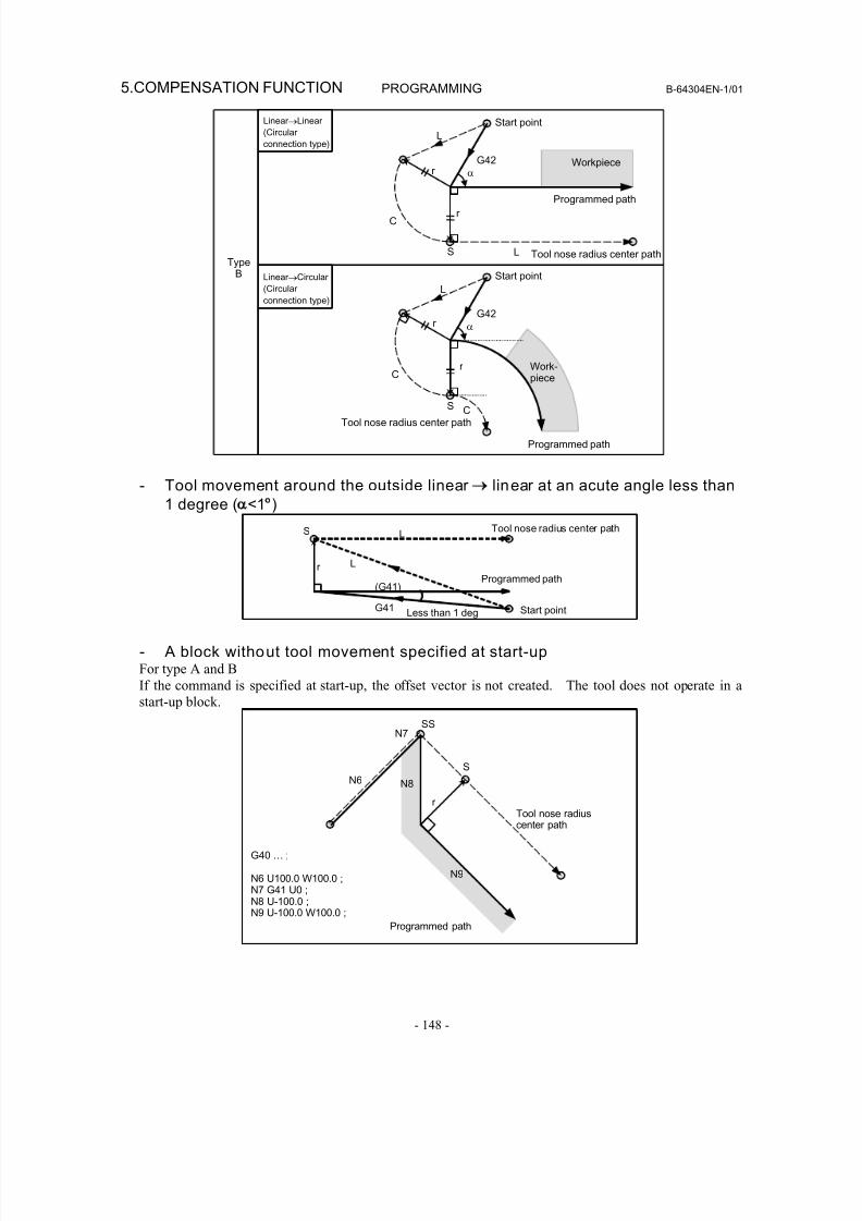
8/16/2019 Manual Operacion para FANUC
http://slidepdf.com/reader/full/manual-operacion-para-fanuc 166/435
5.COMPENSATION FUNCTION PROGRAMMING B-64304EN-1/01
- 148 -
TypeB
Programmed path
α
G42
Start point
L
L
C
S
r
r
Tool nose radius center path
α
G42
Start point
L
C
S
r
r
Programmed path
Tool nose radius center pathC
Workpiece
Work-
piece
Linear →Linear
(Circular
connection type)
Linear →Circular
(Circular
connection type)
- Tool movement around the outside linear → linear at an acute angle less than
1 degree ( <1°)
r
G41
(G41)
L
L
S
Start point
Tool nose radius center path
Programmed path
Less than 1 deg
- A block without tool movement specified at start-upFor type A and B
If the command is specified at start-up, the offset vector is not created. The tool does not operate in a
start-up block.
Programmed path
Tool nose radiuscenter path
S
N9
N6
N7
N8
SS
r
G40 … ;
N6 U100.0 W100.0 ;N7 G41 U0 ;N8 U-100.0 ;N9 U-100.0 W100.0 ;
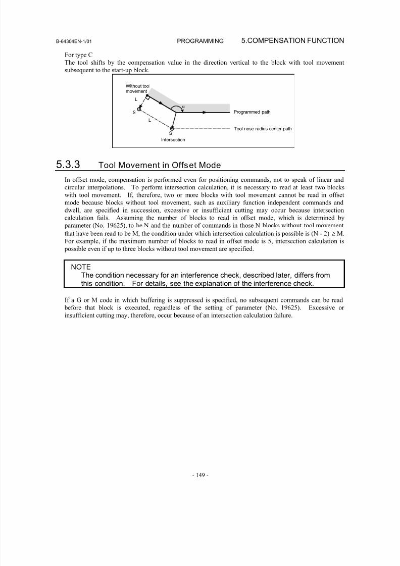
8/16/2019 Manual Operacion para FANUC
http://slidepdf.com/reader/full/manual-operacion-para-fanuc 167/435
B-64304EN-1/01 PROGRAMMING 5.COMPENSATION FUNCTION
- 149 -
For type C
The tool shifts by the compensation value in the direction vertical to the block with tool movement
subsequent to the start-up block.
Programmed path
Tool nose radius center path
S
Intersection
α
L
L
Without toolmovement
S
5.3.3 Tool Movement in Offset Mode
In offset mode, compensation is performed even for positioning commands, not to speak of linear andcircular interpolations. To perform intersection calculation, it is necessary to read at least two blocks
with tool movement. If, therefore, two or more blocks with tool movement cannot be read in offset
mode because blocks without tool movement, such as auxiliary function independent commands and
dwell, are specified in succession, excessive or insufficient cutting may occur because intersection
calculation fails. Assuming the number of blocks to read in offset mode, which is determined by
parameter (No. 19625), to be N and the number of commands in those N blocks without tool movement
that have been read to be M, the condition under which intersection calculation is possible is (N - 2) ≥ M.
For example, if the maximum number of blocks to read in offset mode is 5, intersection calculation is
possible even if up to three blocks without tool movement are specified.
NOTEThe condition necessary for an interference check, described later, differs fromthis condition. For details, see the explanation of the interference check.
If a G or M code in which buffering is suppressed is specified, no subsequent commands can be read
before that block is executed, regardless of the setting of parameter (No. 19625). Excessive or
insufficient cutting may, therefore, occur because of an intersection calculation failure.
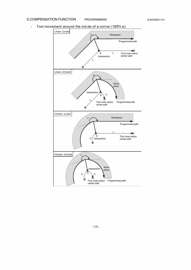
8/16/2019 Manual Operacion para FANUC
http://slidepdf.com/reader/full/manual-operacion-para-fanuc 168/435
5.COMPENSATION FUNCTION PROGRAMMING B-64304EN-1/01
- 150 -
- Tool movement around the inside of a corner (180° )
α
C
L
S
S
α
L
L
Linear →Linear
Programmed path
Intersection
Tool nose radiuscenter path
Workpiece
S
Linear →Circular
Intersection
Programmed pathTool nose radiuscenter path
Work-piece
Circular →Linear
α
Intersection
L
C
Programmed path
Tool nose radiuscenter path
S
CC
Circular →Circular
Programmed path
Intersection
α
Workpiece
Tool nose radiuscenter path
Work-
piece
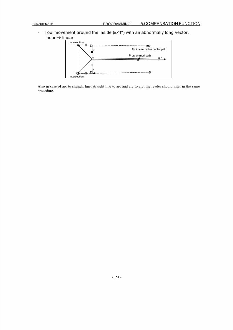
8/16/2019 Manual Operacion para FANUC
http://slidepdf.com/reader/full/manual-operacion-para-fanuc 169/435
B-64304EN-1/01 PROGRAMMING 5.COMPENSATION FUNCTION
- 151 -
- Tool movement around the inside ( <1°) with an abnormally long vector,
linear → linearIntersection
Intersection
r
r
Programmed path
Tool nose radius center path
r
S
Also in case of arc to straight line, straight line to arc and arc to arc, the reader should infer in the same
procedure.
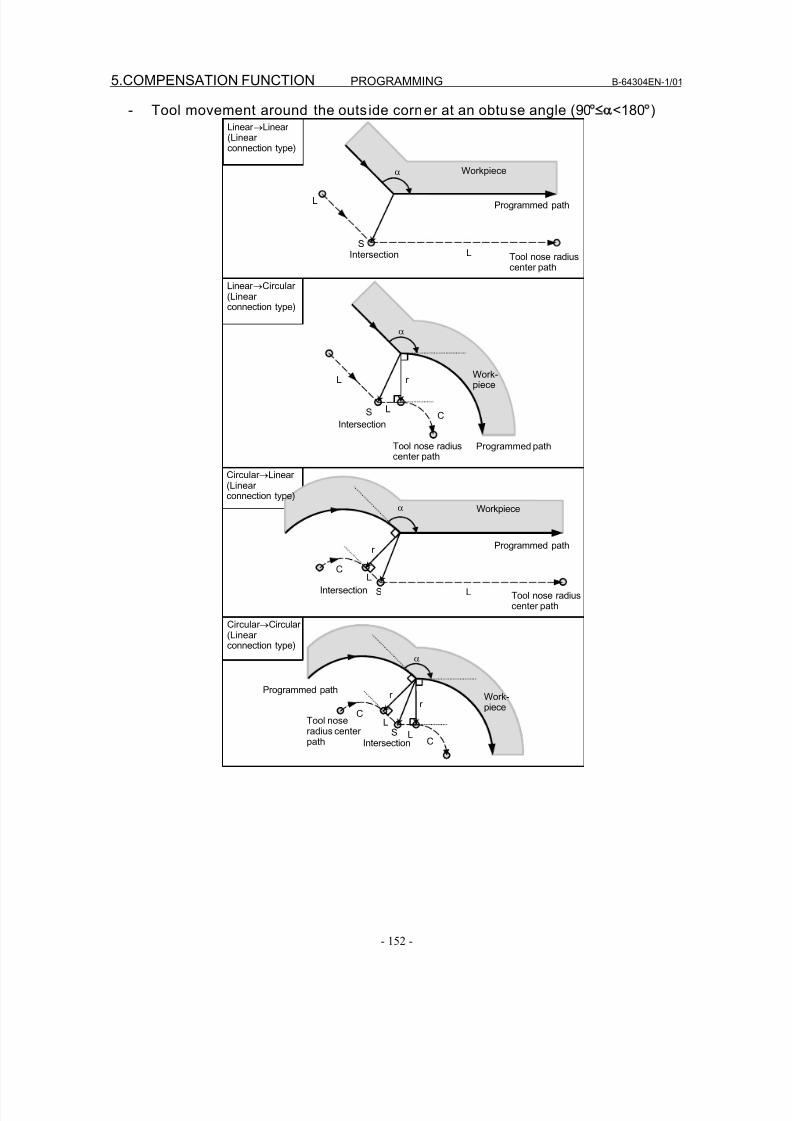
8/16/2019 Manual Operacion para FANUC
http://slidepdf.com/reader/full/manual-operacion-para-fanuc 170/435
5.COMPENSATION FUNCTION PROGRAMMING B-64304EN-1/01
- 152 -
- Tool movement around the outs ide corner at an obtuse angle (90° <180°)Linear →Linear (Linear connection type)
Tool nose radiuscenter path
Tool nose radiuscenter path
Programmed path
α
Programmed path
L
Workpiece
SIntersection
L
r
α
C
Work-piece
L
S L
α
C
LS
Workpiece
r
L
α
Tool noseradius center path
L
LSIntersection
r
r
C
C
Linear →Circular (Linear connection type)
Circular →Linear (Linear connection type)
Circular →Circular (Linear connection type)
Intersection
Tool nose radiuscenter path
Programmed path
Intersection
Programmed path
Work-piece
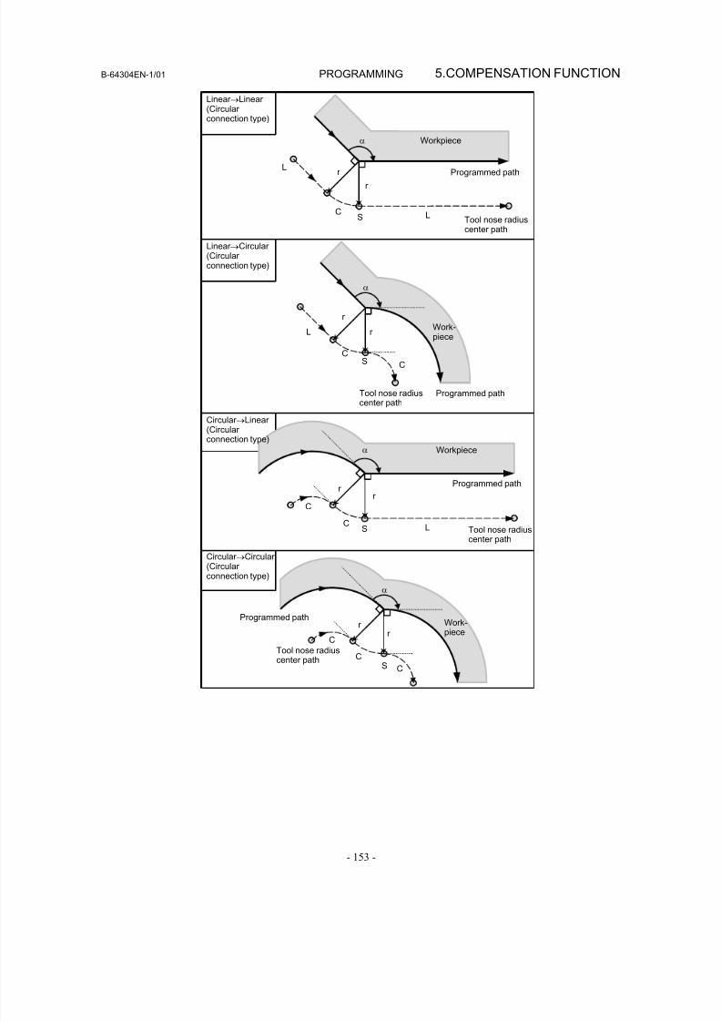
8/16/2019 Manual Operacion para FANUC
http://slidepdf.com/reader/full/manual-operacion-para-fanuc 171/435
B-64304EN-1/01 PROGRAMMING 5.COMPENSATION FUNCTION
- 153 -
α
LS
L
C
r
r
r
α
C
L
SC
r
α
C
LS
r
C
r
Linear →Linear (Circular connection type)
Linear →Circular (Circular connection type)
Circular →Linear (Circular connection type)
Circular →Circular (Circular connection type)
Tool nose radiuscenter path
Programmed path
Workpiece
Tool nose radiuscenter path
Programmed path
Work-piece
Workpiece
Tool nose radiuscenter path
Programmed path
Programmed path
α
S
r r
C
C
CTool nose radiuscenter path
Work-piece
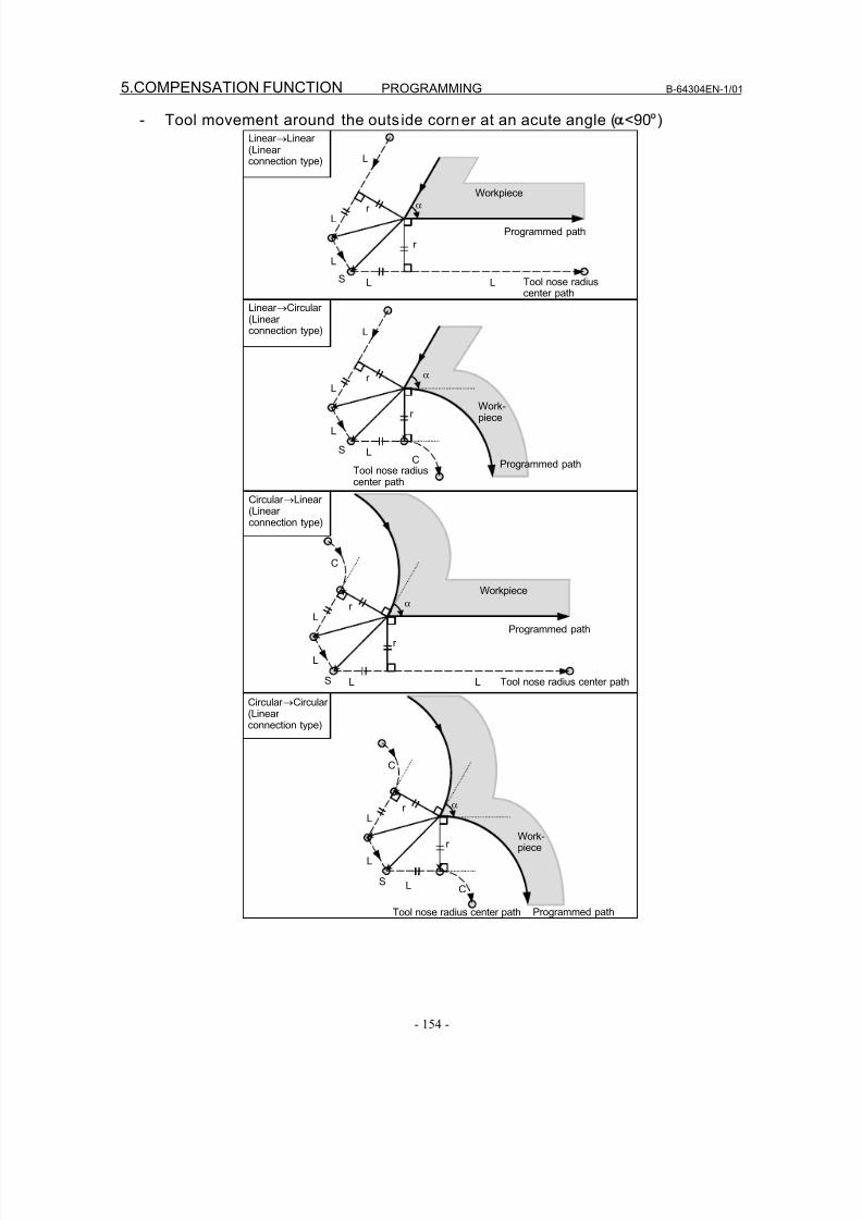
8/16/2019 Manual Operacion para FANUC
http://slidepdf.com/reader/full/manual-operacion-para-fanuc 172/435
5.COMPENSATION FUNCTION PROGRAMMING B-64304EN-1/01
- 154 -
- Tool movement around the outs ide corner at an acute angle ( <90°)
C
α
L L
L
r
r
L
S
α
L
L
S
r
r
L
L
C
Linear →Linear (Linear connection type)
Linear →Circular (Linear connection type)
Circular →Linear (Linear connection type)
Circular →Circular (Linear connection type)
Tool nose radiuscenter path
Programmed path
α
L
L L
L
S
r
r
L
Workpiece
Work-piece
Tool nose radiuscenter path
Programmed path
Tool nose radius center path
Programmed path
Workpiece
α
L
S
r
r
L
C
CL
Work-piece
Tool nose radius center path Programmed path
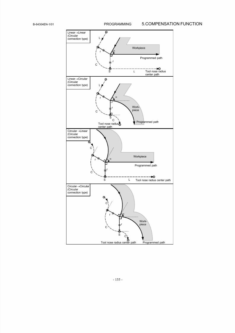
8/16/2019 Manual Operacion para FANUC
http://slidepdf.com/reader/full/manual-operacion-para-fanuc 173/435
B-64304EN-1/01 PROGRAMMING 5.COMPENSATION FUNCTION
- 155 -
α
L
LS
r
r
C
α
S
r
r
C
L
C
C
α
C
L
r
r
S
Linear →Linear (Circular connection type)
Linear →Circular (Circular connection type)
Circular →Linear (Circular connection type)
Circular →Circular (Circular connection type)
Tool nose radiuscenter path
Programmed path
Workpiece
Work-piece
Tool nose radiuscenter path
Programmed path
Tool nose radius center path
Programmed path
Workpiece
α
S
r
r
C
C
C
Work-piece
Tool nose radius center path Programmed path
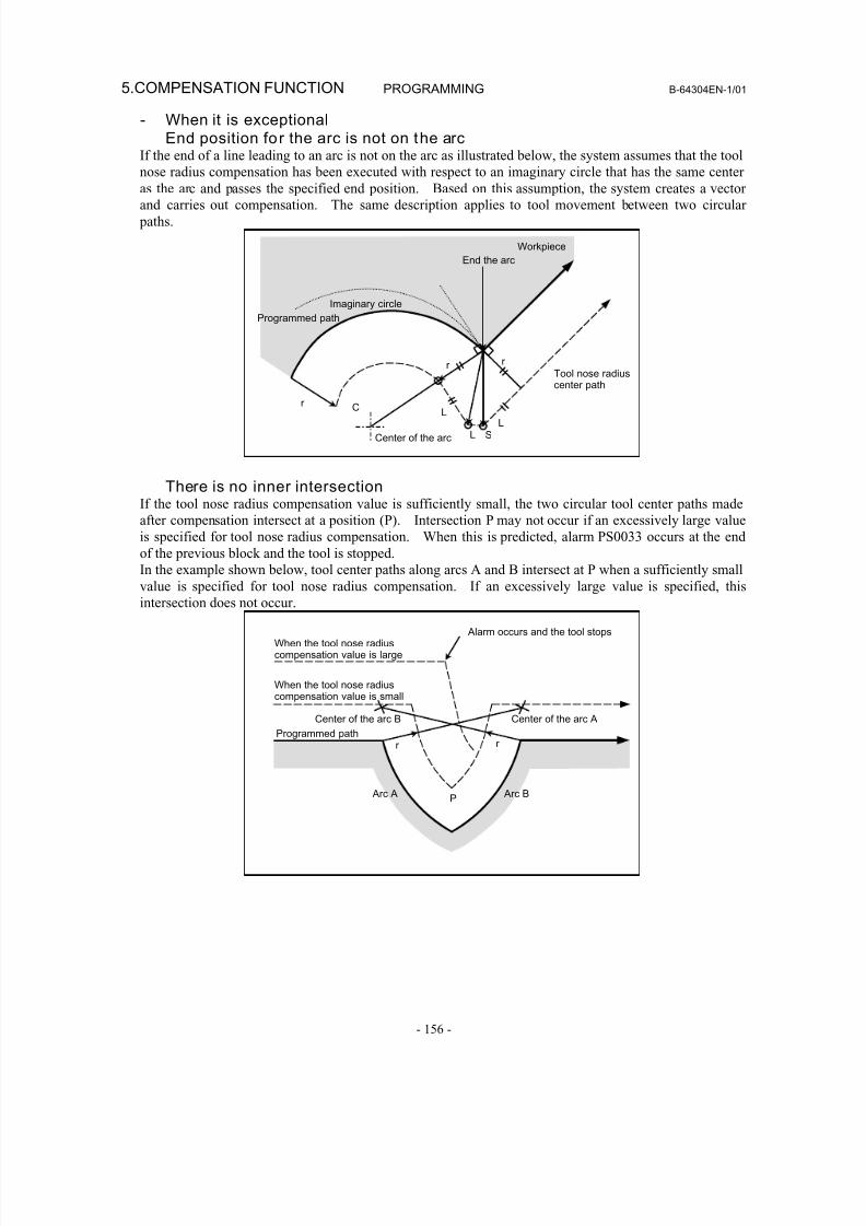
8/16/2019 Manual Operacion para FANUC
http://slidepdf.com/reader/full/manual-operacion-para-fanuc 174/435
5.COMPENSATION FUNCTION PROGRAMMING B-64304EN-1/01
- 156 -
- When it is exceptionalEnd position for the arc is not on the arc
If the end of a line leading to an arc is not on the arc as illustrated below, the system assumes that the tool
nose radius compensation has been executed with respect to an imaginary circle that has the same center
as the arc and passes the specified end position. Based on this assumption, the system creates a vectorand carries out compensation. The same description applies to tool movement between two circular
paths.
Tool nose radius
center path
Programmed path
r r
Center of the arc
Imaginary circle
End the arc
L
LL
r C
S
Workpiece
There is no inner intersectionIf the tool nose radius compensation value is sufficiently small, the two circular tool center paths made
after compensation intersect at a position (P). Intersection P may not occur if an excessively large value
is specified for tool nose radius compensation. When this is predicted, alarm PS0033 occurs at the end
of the previous block and the tool is stopped.
In the example shown below, tool center paths along arcs A and B intersect at P when a sufficiently small
value is specified for tool nose radius compensation. If an excessively large value is specified, this
intersection does not occur.
P
r r
When the tool nose radiuscompensation value is small
When the tool nose radiuscompensation value is large
Programmed path
Alarm occurs and the tool stops
Center of the arc ACenter of the arc B
Arc A Arc B
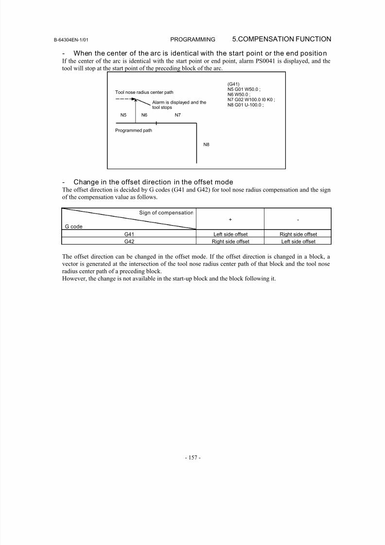
8/16/2019 Manual Operacion para FANUC
http://slidepdf.com/reader/full/manual-operacion-para-fanuc 175/435
B-64304EN-1/01 PROGRAMMING 5.COMPENSATION FUNCTION
- 157 -
- When the center of the arc is identical with the start point or the end positionIf the center of the arc is identical with the start point or end point, alarm PS0041 is displayed, and the
tool will stop at the start point of the preceding block of the arc.
N8
(G41)N5 G01 W50.0 ;N6 W50.0 ;N7 G02 W100.0 I0 K0 ;N8 G01 U-100.0 ;
Alarm is displayed and thetool stops
Programmed path
Tool nose radius center path
N6 N7N5
- Change in the offset direction in the offset modeThe offset direction is decided by G codes (G41 and G42) for tool nose radius compensation and the sign
of the compensation value as follows.
Sign of compensation
G code
+ -
G41 Left side offset Right side offset
G42 Right side offset Left side offset
The offset direction can be changed in the offset mode. If the offset direction is changed in a block, avector is generated at the intersection of the tool nose radius center path of that block and the tool nose
radius center path of a preceding block.
However, the change is not available in the start-up block and the block following it.
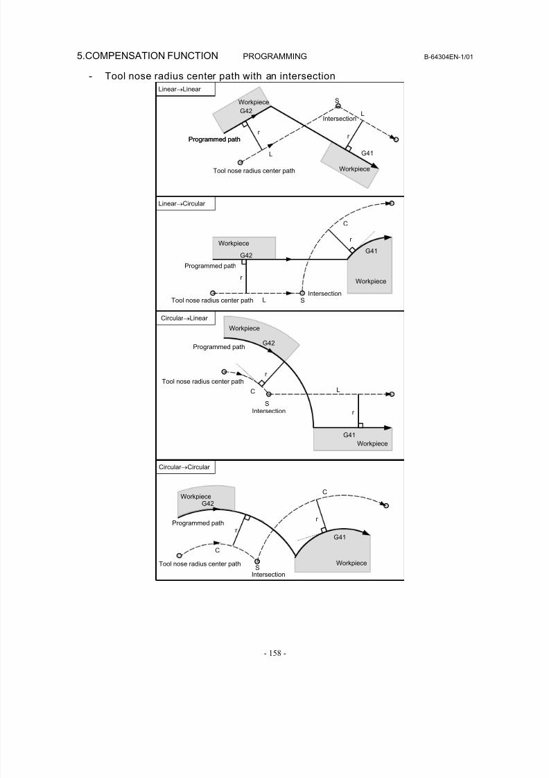
8/16/2019 Manual Operacion para FANUC
http://slidepdf.com/reader/full/manual-operacion-para-fanuc 176/435
5.COMPENSATION FUNCTION PROGRAMMING B-64304EN-1/01
- 158 -
- Tool nose radius center path with an intersection
Linear →Linear
Linear →Circular
Circular →Linear
Circular →Circular
Programmed path
Tool nose radius center path
L
L
S
r r
G42
G41
Workpiece
Intersection
L
G41G42
r
r
S
C
r
r
LC
S
G41
G42
S
G41
G42
C
C
r
r
Workpiece
Workpiece
Programmed path
Programmed path
Intersection
Workpiece
Tool nose radius center path
Workpiece
Programmed path
Tool nose radius center path
Intersection
Workpiece
Tool nose radius center path
Workpiece
Intersection
Workpiece
Programmed path
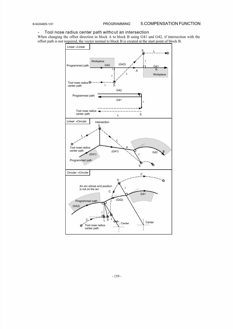
8/16/2019 Manual Operacion para FANUC
http://slidepdf.com/reader/full/manual-operacion-para-fanuc 177/435
B-64304EN-1/01 PROGRAMMING 5.COMPENSATION FUNCTION
- 159 -
- Tool nose radius center path without an intersectionWhen changing the offset direction in block A to block B using G41 and G42, if intersection with the
offset path is not required, the vector normal to block B is created at the start point of block B.
An arc whose end positionis not on the arc
Tool nose radiuscenter path
L
G41
C
C
r
r r
(G42)
S
SCenter Center
Linear →Circular
Tool nose radiuscenter path
Programmed path
Programmed path
Tool nose radiuscenter path
L S
L
S
(G41) G42
A
B
Programmed path
Tool nose radiuscenter path
L
S
r
Circular →Circular
(G41)
Linear →Linear
Intersection
G41B
G42 (G42)
L
L
L
A
r
r
S
G42
G41
Workpiece
S
r
Workpiece
L
(G42)
Programmed path
C
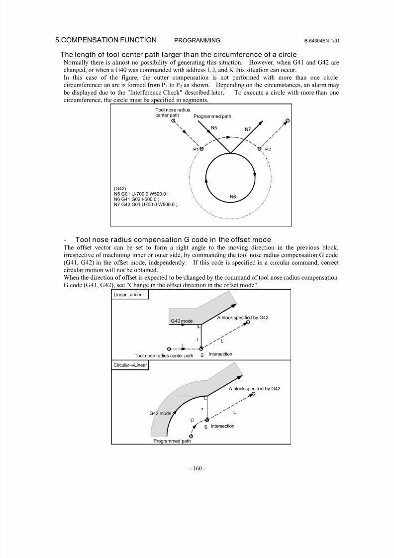
8/16/2019 Manual Operacion para FANUC
http://slidepdf.com/reader/full/manual-operacion-para-fanuc 178/435
5.COMPENSATION FUNCTION PROGRAMMING B-64304EN-1/01
- 160 -
The length of tool center path larger than the circumference of a circle Normally there is almost no possibility of generating this situation. However, when G41 and G42 are
changed, or when a G40 was commanded with address I, J, and K this situation can occur.
In this case of the figure, the cutter compensation is not performed with more than one circle
circumference: an arc is formed from P1 to P2 as shown. Depending on the circumstances, an alarm may be displayed due to the "Interference Check" described later. To execute a circle with more than one
circumference, the circle must be specified in segments.
(G42)N5 G01 U-700.0 W500.0 ;N6 G41 G02 I-500.0 ;N7 G42 G01 U700.0 W500.0 ;
N7
P1 P2
N6
N5
Tool nose radiuscenter path Programmed path
- Tool nose radius compensation G code in the offset modeThe offset vector can be set to form a right angle to the moving direction in the previous block,
irrespective of machining inner or outer side, by commanding the tool nose radius compensation G code
(G41, G42) in the offset mode, independently. If this code is specified in a circular command, correctcircular motion will not be obtained.
When the direction of offset is expected to be changed by the command of tool nose radius compensation
G code (G41, G42), see "Change in the offset direction in the offset mode".
A block specified by G42
Linear →Linear
Tool nose radius center path
Circular →Linear
IntersectionS
r
G42 mode
LL
Programmed path
r
CIntersectionS
LG42 mode
A block specified by G42
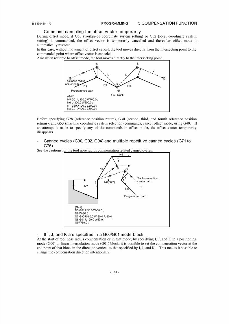
8/16/2019 Manual Operacion para FANUC
http://slidepdf.com/reader/full/manual-operacion-para-fanuc 179/435
B-64304EN-1/01 PROGRAMMING 5.COMPENSATION FUNCTION
- 161 -
- Command canceling the offset vector temporarilyDuring offset mode, if G50 (workpiece coordinate system setting) or G52 (local coordinate system
setting) is commanded, the offset vector is temporarily cancelled and thereafter offset mode is
automatically restored.
In this case, without movement of offset cancel, the tool moves directly from the intersecting point to thecommanded point where offset vector is canceled.
Also when restored to offset mode, the tool moves directly to the intersecting point.
Tool nose radiuscenter path
Programmed path N7
G50 block(G41)N5 G01 U300.0 W700.0 ;N6 U-300.0 W600.0 ;N7 G50 X100.0 Z200.0 ;N8 G01 X400.0 Z800.0 ;
S
L
L L
L
S
SN5 N6 N8
Before specifying G28 (reference position return), G30 (second, third, and fourth reference position
returns), and G53 (machine coordinate system selection) commands, cancel offset mode, using G40. If
an attempt is made to specify any of the commands in offset mode, the offset vector temporarily
disappears.
- Canned cycles (G90, G92, G94) and multiple repetit ive canned cycles (G71 toG76)
See the cautions for the tool nose radius compensation related canned cycles.
Tool nose radiuscenter path
(G42)N5 G01 U50.0 W-60.0 ;N6 W-80.0 ;N7 G90 U-60.0 W-80.0 R-30.0 ;N8 G01 U120.0 W50.0 ;N9 W50.0 ;
N5
N6(G42)
N7
N8
N9
SS
S
Programmed path
r
r
- If I, J, and K are specified in a G00/G01 mode blockAt the start of tool nose radius compensation or in that mode, by specifying I, J, and K in a positioning
mode (G00) or linear interpolation mode (G01) block, it is possible to set the compensation vector at the
end point of that block in the direction vertical to that specified by I, J, and K. This makes it possible to
change the compensation direction intentionally.
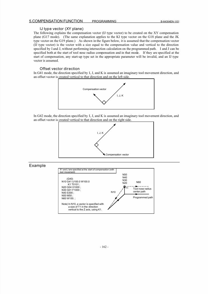
8/16/2019 Manual Operacion para FANUC
http://slidepdf.com/reader/full/manual-operacion-para-fanuc 180/435
5.COMPENSATION FUNCTION PROGRAMMING B-64304EN-1/01
- 162 -
IJ type vector (XY plane)The following explains the compensation vector (IJ type vector) to be created on the XY compensation
plane (G17 mode). (The same explanation applies to the KI type vector on the G18 plane and the JK
type vector on the G19 plane.) As shown in the figure below, it is assumed that the compensation vector
(IJ type vector) is the vector with a size equal to the compensation value and vertical to the directionspecified by I and J, without performing intersection calculation on the programmed path. I and J can be
specified both at the start of tool nose radius compensation and in that mode. If they are specified at the
start of compensation, any start-up type set in the appropriate parameter will be invalid, and an IJ type
vector is assumed.
Offset vector directionIn G41 mode, the direction specified by I, J, and K is assumed an imaginary tool movement direction, and
an offset vector is created vertical to that direction and on the left side.
Compensation vector
I, J, K
In G42 mode, the direction specified by I, J, and K is assumed an imaginary tool movement direction, and
an offset vector is created vertical to that direction and on the right side.
Compensation vector
I, J, K
Example
Programmed path
(G40)N10 G41 U100.0 W100.0
K1 T0101 ;N20 G04 X1000 ;N30 G01 F1000 ;N40 S300 ;N50 M50 ;N60 W150. ;
Note) In N10, a vector is specified witha size of T1 in the directionvertical to the Z axis, using K1.
If I and J are specified at the start of compensation (withtool movement)
Tool nose radiuscenter path
T1
N10
N50N40N30N20 N60
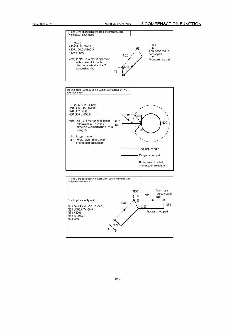
8/16/2019 Manual Operacion para FANUC
http://slidepdf.com/reader/full/manual-operacion-para-fanuc 181/435
B-64304EN-1/01 PROGRAMMING 5.COMPENSATION FUNCTION
- 163 -
If I and J are specified at the start of compensation(without tool movement)
(G40)N10 G41 K1 T0101 ;N20 U100.0 W100.0 ;
N30 W150.0 ;
Note) In N10, a vector is specifiedwith a size of T1 in thedirection vertical to the Zaxis, using K1.
Tool nose radiuscenter path
Programmed path
N10
N20
N30
T1
(G17 G41 T0101)N10 G00 U150.0 J50.0 ;N20 G02 I50.0 ;N30 G00 U-150.0 ;
Note) In N10, a vector is specifiedwith a size of T1 in thedirection vertical to the Y axis,using J50.
<1> IJ type vector<2> Vector determined with
intersection calculation
If I and J are specified at the start of compensation (withtool movement)
Path determined withintersection calculation
Programmed path
Tool center path
<1>
<2>
<2>
(I,J)
N10 N20N30
Start-up/cancel type C
N10 G41 T0101 G01 F1000 ;N20 U100.0 W100.0 ;N30 K10.0 ;N40 W150.0 ;N50 G40 ;
If I and J are specified in a block without tool movement incompensation mode
N10
N30
N20
N40
N50
S S
T1
Tool noseradius centerpath
Programmed path
(I, J)
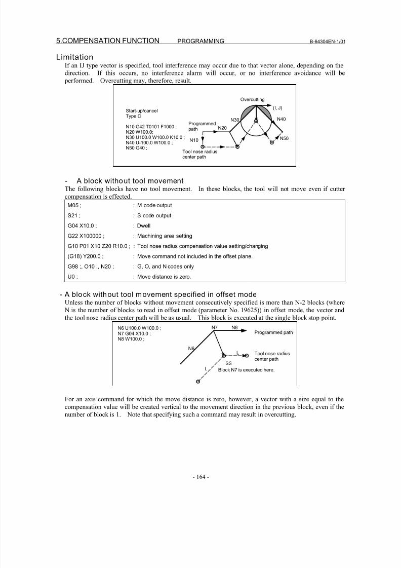
8/16/2019 Manual Operacion para FANUC
http://slidepdf.com/reader/full/manual-operacion-para-fanuc 182/435
5.COMPENSATION FUNCTION PROGRAMMING B-64304EN-1/01
- 164 -
LimitationIf an IJ type vector is specified, tool interference may occur due to that vector alone, depending on the
direction. If this occurs, no interference alarm will occur, or no interference avoidance will be
performed. Overcutting may, therefore, result.
Start-up/cancelType C
N10 G42 T0101 F1000 ;N20 W100.0;N30 U100.0 W100.0 K10.0 ;N40 U-100.0 W100.0 ;N50 G40 ;
Tool nose radiuscenter path
Overcutting
Programmedpath
N10
N30
N20
N40
N50
(I, J)
- A block without tool movementThe following blocks have no tool movement. In these blocks, the tool will not move even if cutter
compensation is effected.
M05 ; : M code output
S21 ; : S code output
G04 X10.0 ; : Dwell
G22 X100000 ; : Machining area setting
G10 P01 X10 Z20 R10.0 ; : Tool nose radius compensation value setting/changing
(G18) Y200.0 ; : Move command not included in the offset plane.
G98 ;, O10 ;, N20 ; : G, O, and N codes onlyU0 ; : Move distance is zero.
- A block without tool movement specified in offset modeUnless the number of blocks without movement consecutively specified is more than N-2 blocks (where
N is the number of blocks to read in offset mode (parameter No. 19625)) in offset mode, the vector and
the tool nose radius center path will be as usual. This block is executed at the single block stop point.
Programmed path
Block N7 is executed here.
Tool nose radiuscenter path
N6 U100.0 W100.0 ;N7 G04 X10.0 ;N8 W100.0 ;
L
N6
N7 N8
L
SS
For an axis command for which the move distance is zero, however, a vector with a size equal to the
compensation value will be created vertical to the movement direction in the previous block, even if the
number of block is 1. Note that specifying such a command may result in overcutting.
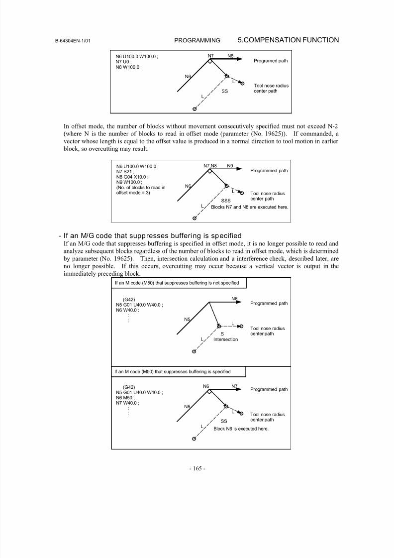
8/16/2019 Manual Operacion para FANUC
http://slidepdf.com/reader/full/manual-operacion-para-fanuc 183/435
B-64304EN-1/01 PROGRAMMING 5.COMPENSATION FUNCTION
- 165 -
N6 U100.0 W100.0 ;N7 U0 ;N8 W100.0 ;
L
N6
N7 N8
L
SS
Programed path
Tool nose radiuscenter path
In offset mode, the number of blocks without movement consecutively specified must not exceed N-2
(where N is the number of blocks to read in offset mode (parameter (No. 19625)). If commanded, a
vector whose length is equal to the offset value is produced in a normal direction to tool motion in earlier
block, so overcutting may result.
N6 U100.0 W100.0 ;N7 S21 ;N8 G04 X10.0 ;N9 W100.0 ;(No. of blocks to read inoffset mode = 3)
L
N6
N7,N8 N9
L
SSS
Programmed path
Blocks N7 and N8 are executed here.
Tool nose radiuscenter path
- If an M/G code that suppresses buffering is specifiedIf an M/G code that suppresses buffering is specified in offset mode, it is no longer possible to read and
analyze subsequent blocks regardless of the number of blocks to read in offset mode, which is determined
by parameter (No. 19625). Then, intersection calculation and a interference check, described later, are
no longer possible. If this occurs, overcutting may occur because a vertical vector is output in the
immediately preceding block.
If an M code (M50) that suppresses buffering is not specified
Programmed path
Tool nose radiuscenter path
(G42)N5 G01 U40.0 W40.0 ;N6 W40.0 ; : :
IntersectionL
N5
N6
L
S
If an M code (M50) that suppresses buffering is specified
(G42)N5 G01 U40.0 W40.0 ;N6 M50 ;N7 W40.0 ; : :
L
N5
N6 N7
L
SS
Block N6 is executed here.
Programmed path
Tool nose radiuscenter path
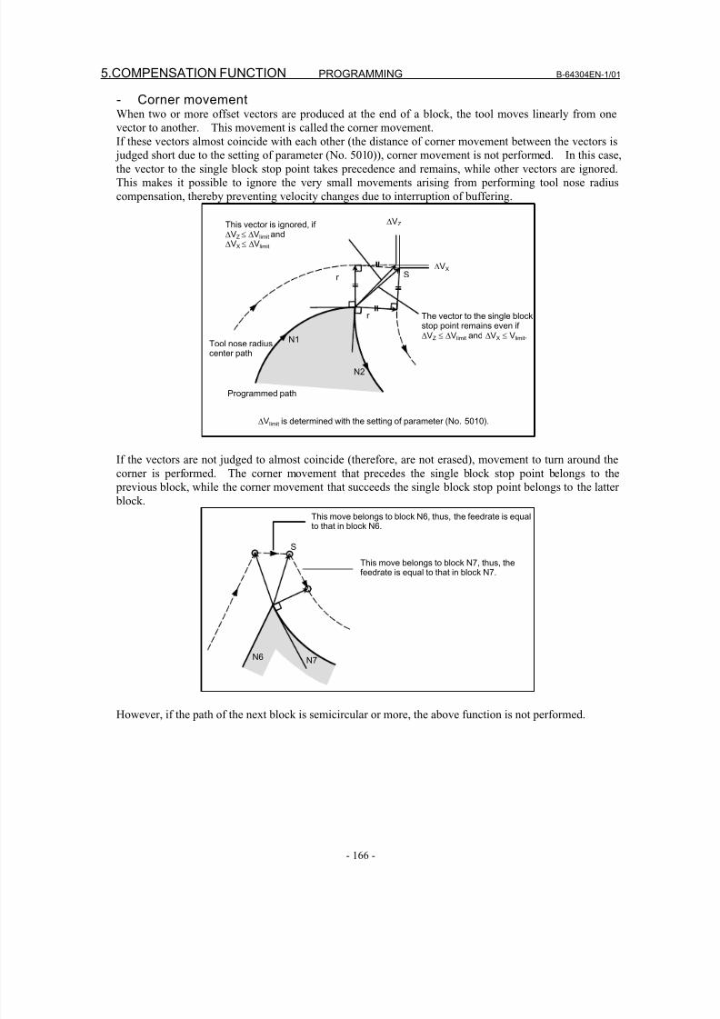
8/16/2019 Manual Operacion para FANUC
http://slidepdf.com/reader/full/manual-operacion-para-fanuc 184/435
5.COMPENSATION FUNCTION PROGRAMMING B-64304EN-1/01
- 166 -
- Corner movementWhen two or more offset vectors are produced at the end of a block, the tool moves linearly from one
vector to another. This movement is called the corner movement.
If these vectors almost coincide with each other (the distance of corner movement between the vectors is
judged short due to the setting of parameter (No. 5010)), corner movement is not performed. In this case,the vector to the single block stop point takes precedence and remains, while other vectors are ignored.
This makes it possible to ignore the very small movements arising from performing tool nose radius
compensation, thereby preventing velocity changes due to interruption of buffering.
The vector to the single blockstop point remains even if ΔVZ ≤ ΔVlimit and ΔVX ≤ Vlimit.
Tool nose radiuscenter path
ΔVlimit is determined with the setting of parameter (No. 5010).
Programmed path
This vector is ignored, if ΔVZ ≤ ΔVlimit andΔVX ≤ ΔVlimit
SΔVX
ΔVZ
r
r N1N1
N2
If the vectors are not judged to almost coincide (therefore, are not erased), movement to turn around the
corner is performed. The corner movement that precedes the single block stop point belongs to the
previous block, while the corner movement that succeeds the single block stop point belongs to the latter
block.
This move belongs to block N7, thus, thefeedrate is equal to that in block N7.
This move belongs to block N6, thus, the feedrate is equalto that in block N6.
S
N6 N7
However, if the path of the next block is semicircular or more, the above function is not performed.
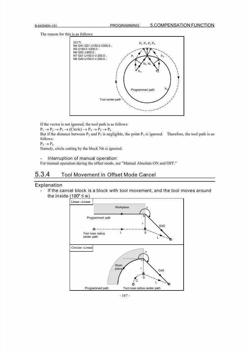
8/16/2019 Manual Operacion para FANUC
http://slidepdf.com/reader/full/manual-operacion-para-fanuc 185/435
B-64304EN-1/01 PROGRAMMING 5.COMPENSATION FUNCTION
- 167 -
The reason for this is as follows:
(G17)N4 G41 G01 U150.0 V200.0 ;N5 U150.0 V200.0 ;N6 G02 J-600.0 ;
N7 G01 U150.0 V-200.0 ;N8 G40 U150.0 V-200.0 ;
Tool center path
P1
P2 P3 P4 P5
P6
N5
N6
N4
N7
N8
Programmed path
If the vector is not ignored, the tool path is as follows:
P1 → P2 → P3 → (Circle) → P4 → P5 → P6
But if the distance between P2 and P3 is negligible, the point P3 is ignored. Therefore, the tool path is as
follows:
P2 → P4
Namely, circle cutting by the block N6 is ignored.
- Interruption of manual operationFor manual operation during the offset mode, see "Manual Absolute ON and OFF."
5.3.4 Tool Movement in Offset Mode Cancel
Explanation- If the cancel block is a block with tool movement, and the tool moves around
the inside (180° )
Linear →Linear
Circular →Linear
Programmed path Tool nose radius center path
Programmed path
Tool nose radiuscenter path
α
L S
G40r
L
Workpiece
α
S
G40r
LC
Work-piece
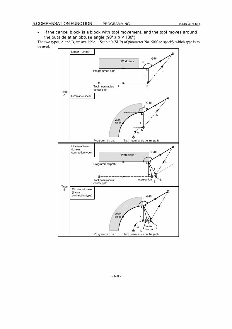
8/16/2019 Manual Operacion para FANUC
http://slidepdf.com/reader/full/manual-operacion-para-fanuc 186/435
5.COMPENSATION FUNCTION PROGRAMMING B-64304EN-1/01
- 168 -
- If the cancel block is a block with tool movement, and the tool moves around
the outside at an obtuse angle (90° < 180°)The two types, A and B, are available. Set bit 0 (SUP) of parameter No. 5003 to specify which type is to
be used.
Linear →Linear
Type A
TypeB
Linear →Linear (Linear connection type)
Circular →Linear
Circular →Linear (Linear connection type)
r
α
Programmed path
Tool nose radiuscenter path
L S
G40
L
Workpiece
Programmed path Tool nose radius center path
L
α
SC
G40
Work-piece r
r
α
Programmed path
Tool nose radiuscenter path
LS
G40
L
Workpiece
Programmed path Tool nose radius center path
L
L
Intersection
α
S
C
G40
Work-piece
r
Inter-section
L
r
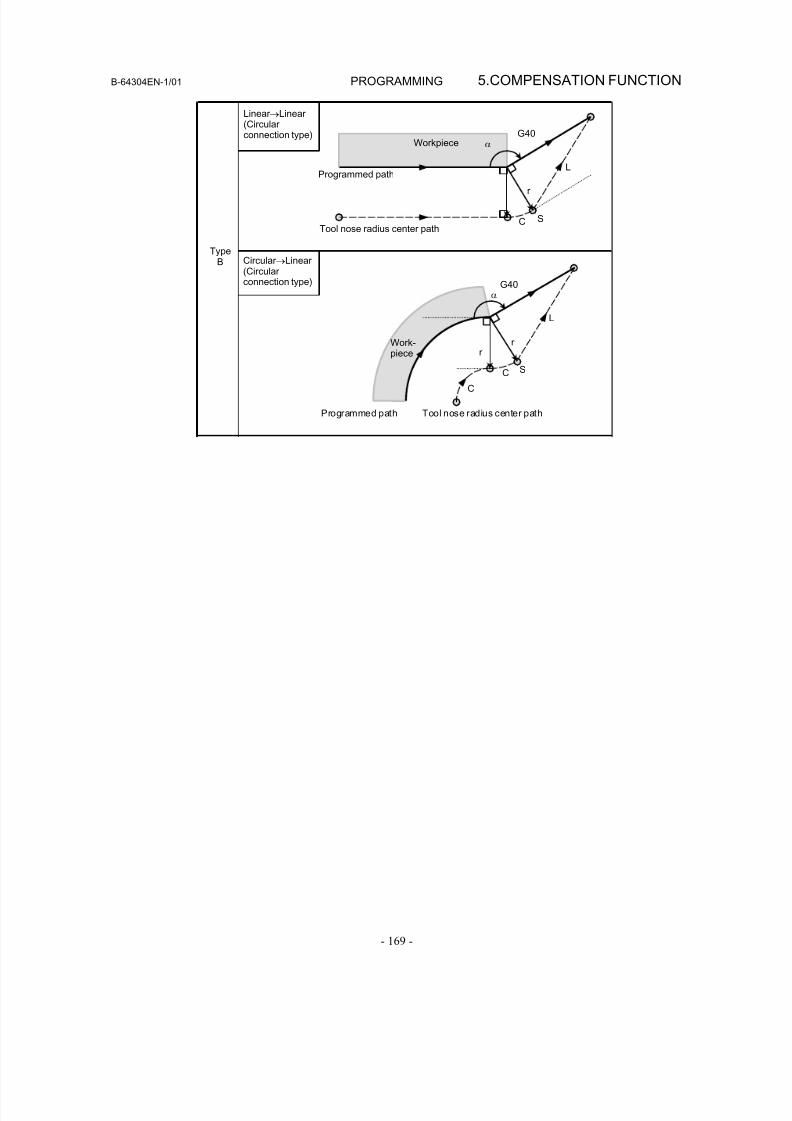
8/16/2019 Manual Operacion para FANUC
http://slidepdf.com/reader/full/manual-operacion-para-fanuc 187/435
B-64304EN-1/01 PROGRAMMING 5.COMPENSATION FUNCTION
- 169 -
TypeB
Linear →Linear (Circular connection type)
Circular →Linear (Circular connection type)
r
α
Programmed path
Tool nose radius center pathC S
G40
L
Workpiece
Programmed path Tool nose radius center path
L
α
C
G40
Work-
piece
r
r
C S
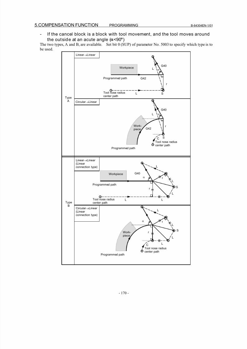
8/16/2019 Manual Operacion para FANUC
http://slidepdf.com/reader/full/manual-operacion-para-fanuc 188/435
5.COMPENSATION FUNCTION PROGRAMMING B-64304EN-1/01
- 170 -
- If the cancel block is a block with tool movement, and the tool moves around
the outside at an acute angle ( <90°)The two types, A and B, are available. Set bit 0 (SUP) of parameter No. 5003 to specify which type is to
be used.
Linear →Linear
Circular →Linear
Type A
TypeB
Linear →Linear
(Linear connection type)
Circular →Linear (Linear connection type)
Programmed path
α
G40L
L S
r
Tool nose radiuscenter path
αL
S
r
Programmed path
Tool nose radiuscenter path
C
Workpiece
Work-piece
G42
G40
G42
Programmed path
α
G40
L
LL
L
Sr
r
Tool nose radiuscenter path
α
L
L
L
Sr
r
Programmed path
Tool nose radiuscenter path
C
L
L
Workpiece
Work-piece
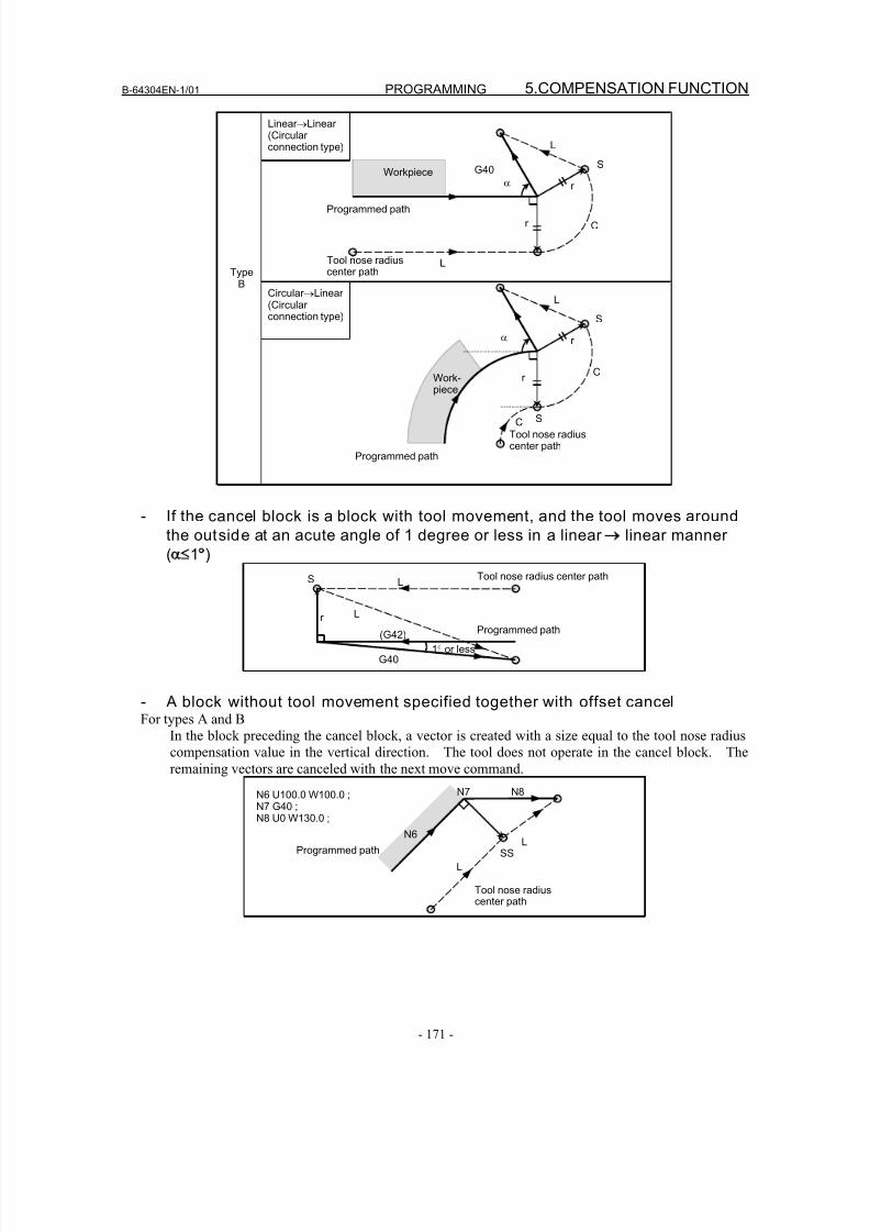
8/16/2019 Manual Operacion para FANUC
http://slidepdf.com/reader/full/manual-operacion-para-fanuc 189/435
B-64304EN-1/01 PROGRAMMING 5.COMPENSATION FUNCTION
- 171 -
TypeB
Linear →Linear (Circular connection type)
Circular →Linear (Circular connection type)
Programmed path
α
G40
L
L
S
Cr
r
Tool nose radiuscenter path
α
L
S
S
r
r
Programmed path
Tool nose radiuscenter path
C
C
Workpiece
Work-
piece
- If the cancel block is a block with tool movement, and the tool moves around
the outside at an acute angle of 1 degree or less in a linear → linear manner
( 1°)
Programmed path
Tool nose radius center path
r
G40
(G42)
L
L
S
1° or less
- A block without tool movement specified together with offset cancelFor types A and B
In the block preceding the cancel block, a vector is created with a size equal to the tool nose radius
compensation value in the vertical direction. The tool does not operate in the cancel block. The
remaining vectors are canceled with the next move command.N6 U100.0 W100.0 ;N7 G40 ;N8 U0 W130.0 ;
Tool nose radiuscenter path
L
N6
N7 N8
LSSProgrammed path
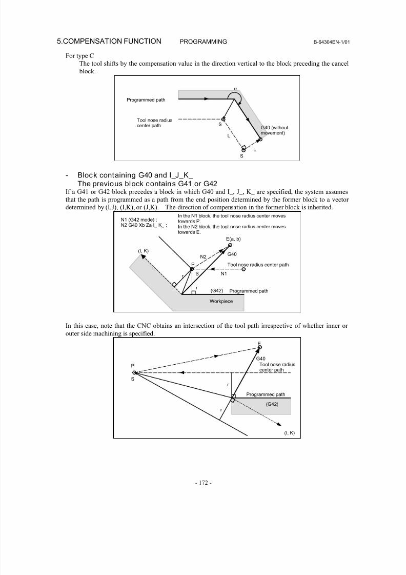
8/16/2019 Manual Operacion para FANUC
http://slidepdf.com/reader/full/manual-operacion-para-fanuc 190/435
5.COMPENSATION FUNCTION PROGRAMMING B-64304EN-1/01
- 172 -
For type C
The tool shifts by the compensation value in the direction vertical to the block preceding the cancel
block.
Tool nose radiuscenter path
Programmed path
α
L
S
L
SG40 (withoutmovement)
- Block containing G40 and I_J_K_The previous block contains G41 or G42
If a G41 or G42 block precedes a block in which G40 and I_, J_, K_ are specified, the system assumes
that the path is programmed as a path from the end position determined by the former block to a vector
determined by (I,J), (I,K), or (J,K). The direction of compensation in the former block is inherited.
Programmed path
N1 (G42 mode) ;N2 G40 Xb Za I_ K_ ;
In the N1 block, the tool nose radius center movestowards P.In the N2 block, the tool nose radius center movestowards E.
E(a, b)
Tool nose radius center path
r
(I, K)
r
P
S
N2
N1
(G42)
Workpiece
G40
In this case, note that the CNC obtains an intersection of the tool path irrespective of whether inner or
outer side machining is specified.
Programmed path
Tool nose radiuscenter path
(I, K)
r
P
S
(G42)
E
G40
r
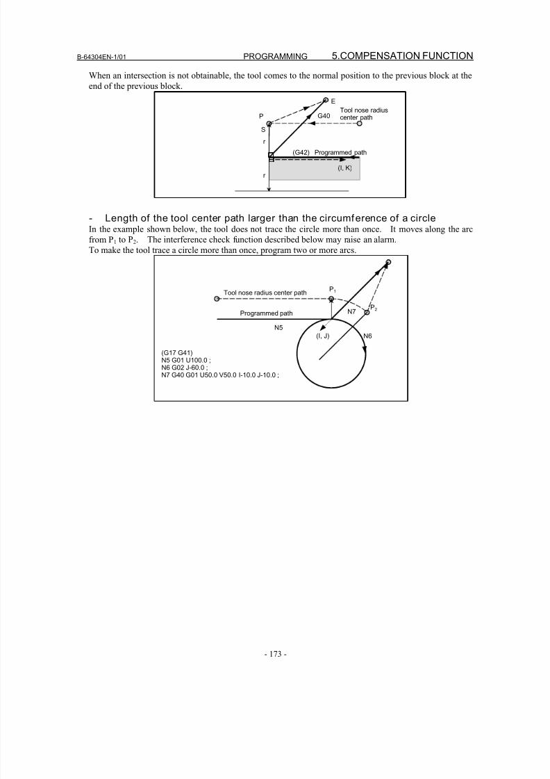
8/16/2019 Manual Operacion para FANUC
http://slidepdf.com/reader/full/manual-operacion-para-fanuc 191/435
B-64304EN-1/01 PROGRAMMING 5.COMPENSATION FUNCTION
- 173 -
When an intersection is not obtainable, the tool comes to the normal position to the previous block at the
end of the previous block.
Programmed path
Tool nose radiuscenter path
E
(I, K)
r
S
G40P
r
(G42)
- Length of the tool center path larger than the circumference of a circleIn the example shown below, the tool does not trace the circle more than once. It moves along the arc
from P1 to P
2. The interference check function described below may raise an alarm.
To make the tool trace a circle more than once, program two or more arcs.
(G17 G41)N5 G01 U100.0 ;
N6 G02 J-60.0 ;N7 G40 G01 U50.0 V50.0 I-10.0 J-10.0 ;
Programmed path
Tool nose radius center path
(I, J)N5
N6
N7
P1
P2
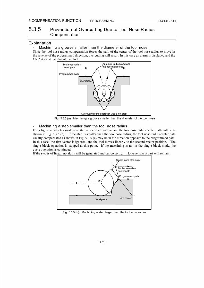
8/16/2019 Manual Operacion para FANUC
http://slidepdf.com/reader/full/manual-operacion-para-fanuc 192/435
5.COMPENSATION FUNCTION PROGRAMMING B-64304EN-1/01
- 174 -
5.3.5 Prevention of Overcutt ing Due to Tool Nose Radius
Compensation
Explanation- Machin ing a groove smaller than the diameter of the tool noseSince the tool nose radius compensation forces the path of the center of the tool nose radius to move in
the reverse of the programmed direction, overcutting will result. In this case an alarm is displayed and the
CNC stops at the start of the block.
Programmed path
Tool nose radiuscenter path
Overcutting if the operation would not stop
Workpiece
An alarm is displayed andthe operation stops
Fig. 5.3.5 (a) Machining a groove smaller than the diameter of the tool nose
- Machin ing a step smaller than the tool nose radiusFor a figure in which a workpiece step is specified with an arc, the tool nose radius center path will be as
shown in Fig. 5.3.5 (b). If the step is smaller than the tool nose radius, the tool nose radius center pathusually compensated as shown in Fig. 5.3.5 (c) may be in the direction opposite to the programmed path.
In this case, the first vector is ignored, and the tool moves linearly to the second vector position. The
single block operation is stopped at this point. If the machining is not in the single block mode, the
cycle operation is continued.
If the step is of linear, no alarm will be generated and cut correctly. However uncut part will remain.
Programmed path
Single block stop point
Tool nose radiuscenter path
Workpiece Arc center
S
S
Fig. 5.3.5 (b) Machining a step larger than the too l nose radius
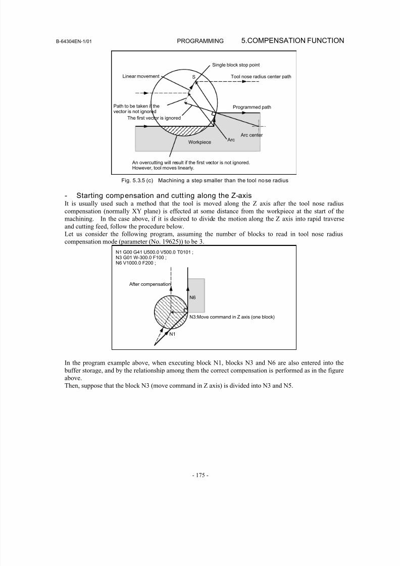
8/16/2019 Manual Operacion para FANUC
http://slidepdf.com/reader/full/manual-operacion-para-fanuc 193/435
B-64304EN-1/01 PROGRAMMING 5.COMPENSATION FUNCTION
- 175 -
Programmed path
An overcutting will result if the first vector is not ignored.However, tool moves linearly.
Tool nose radius center path
Workpiece
Arc center
Single block stop point
S
Arc
Linear movement
The first vector is ignored
Path to be taken if thevector is not ignored
Fig. 5.3.5 (c) Machining a step smaller than the tool nose radius
- Starting compensation and cutt ing along the Z-axisIt is usually used such a method that the tool is moved along the Z axis after the tool nose radius
compensation (normally XY plane) is effected at some distance from the workpiece at the start of the
machining. In the case above, if it is desired to divide the motion along the Z axis into rapid traverse
and cutting feed, follow the procedure below.
Let us consider the following program, assuming the number of blocks to read in tool nose radius
compensation mode (parameter (No. 19625)) to be 3.
N1 G00 G41 U500.0 V500.0 T0101 ;N3 G01 W-300.0 F100 ;N6 V1000.0 F200 ;
N1
N3:Move command in Z axis (one block)
N6
After compensation
In the program example above, when executing block N1, blocks N3 and N6 are also entered into the
buffer storage, and by the relationship among them the correct compensation is performed as in the figure
above.
Then, suppose that the block N3 (move command in Z axis) is divided into N3 and N5.
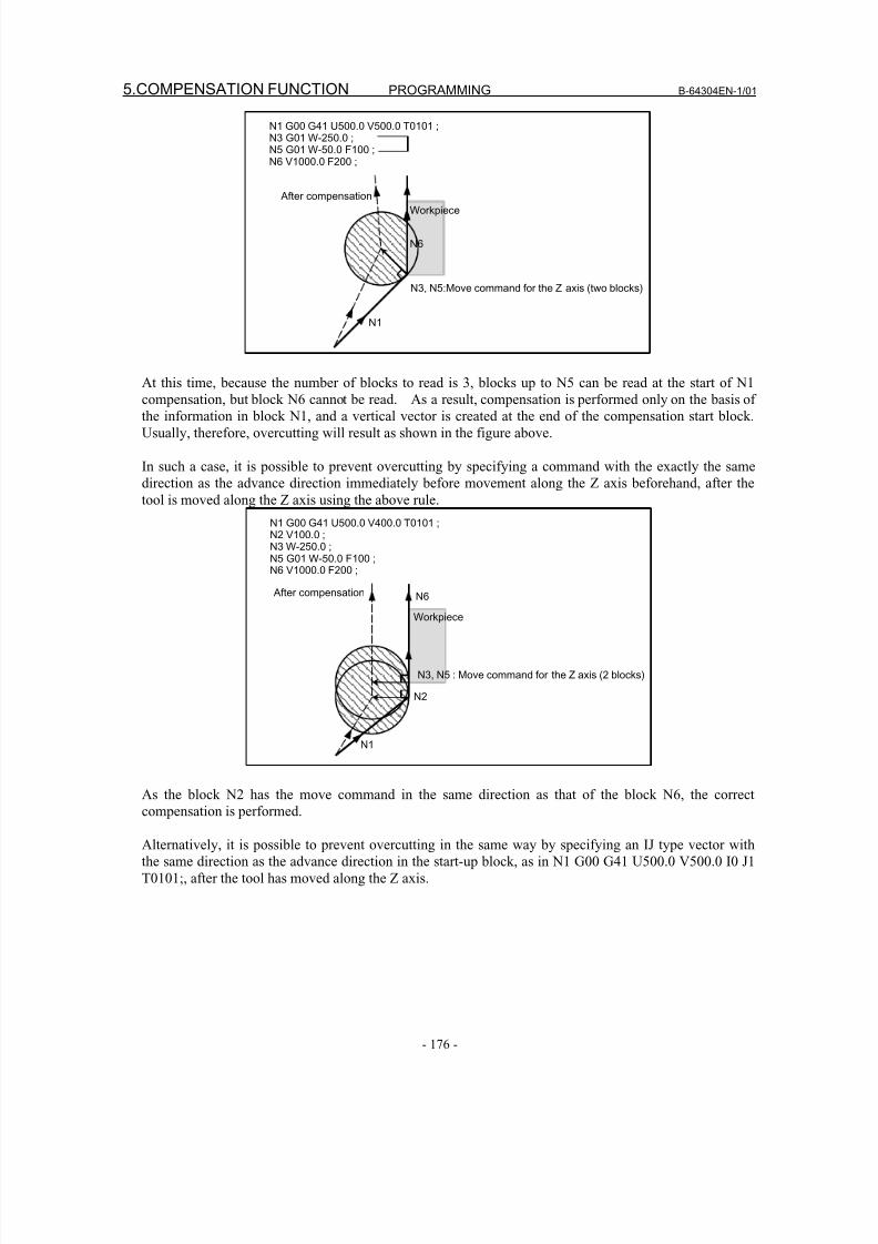
8/16/2019 Manual Operacion para FANUC
http://slidepdf.com/reader/full/manual-operacion-para-fanuc 194/435
5.COMPENSATION FUNCTION PROGRAMMING B-64304EN-1/01
- 176 -
N1 G00 G41 U500.0 V500.0 T0101 ; N3 G01 W-250.0 ; N5 G01 W-50.0 F100 ; N6 V1000.0 F200 ;
N3, N5:Move command for the Z axis (two blocks)
After compensation
N1
N6
Workpiece
At this time, because the number of blocks to read is 3, blocks up to N5 can be read at the start of N1
compensation, but block N6 cannot be read. As a result, compensation is performed only on the basis of
the information in block N1, and a vertical vector is created at the end of the compensation start block.
Usually, therefore, overcutting will result as shown in the figure above.
In such a case, it is possible to prevent overcutting by specifying a command with the exactly the same
direction as the advance direction immediately before movement along the Z axis beforehand, after the
tool is moved along the Z axis using the above rule.
N1 G00 G41 U500.0 V400.0 T0101 ; N2 V100.0 ; N3 W-250.0 ; N5 G01 W-50.0 F100 ; N6 V1000.0 F200 ;
Workpiece
N1
N6 After compensation
N2
N3, N5 : Move command for the Z axis (2 blocks)
As the block N2 has the move command in the same direction as that of the block N6, the correct
compensation is performed.
Alternatively, it is possible to prevent overcutting in the same way by specifying an IJ type vector with
the same direction as the advance direction in the start-up block, as in N1 G00 G41 U500.0 V500.0 I0 J1
T0101;, after the tool has moved along the Z axis.
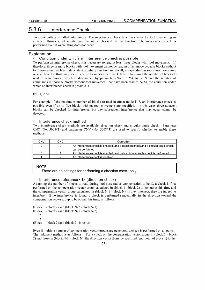
8/16/2019 Manual Operacion para FANUC
http://slidepdf.com/reader/full/manual-operacion-para-fanuc 195/435
B-64304EN-1/01 PROGRAMMING 5.COMPENSATION FUNCTION
- 177 -
5.3.6 Interference Check
Tool overcutting is called interference. The interference check function checks for tool overcutting in
advance. However, all interference cannot be checked by this function. The interference check is
performed even if overcutting does not occur.
Explanation- Condition under which an interference check is possibleTo perform an interference check, it is necessary to read at least three blocks with tool movement. If,
therefore, three or more blocks with tool movement cannot be read in offset mode because blocks without
tool movement, such as independent auxiliary function and dwell, are specified in succession, excessive
or insufficient cutting may occur because an interference check fails. Assuming the number of blocks to
read in offset mode, which is determined by parameter (No. 19625), to be N and the number of
commands in those N blocks without tool movement that have been read to be M, the condition under
which an interference check is possible is
(N - 3) ≥ M.
For example, if the maximum number of blocks to read in offset mode is 8, an interference check is
possible even if up to five blocks without tool movement are specified. In this case, three adjacent
blocks can be checked for interference, but any subsequent interference that may occur cannot be
detected.
- Interference check methodTwo interference check methods are available, direction check and circular angle check. Parameter
CNC (No. 5008#1) and parameter CNV (No. 5008#3) are used to specify whether to enable these
methods.
CNV CNC Operation
0 0 An interference check is enabled, and a direction check and a circular angle check
can be performed.
0 1 An interference check is enabled, and only a circular angle check is performed.
1 – An interference check is disabled.
NOTEThere are no settings for performing a direction check only.
- Interference reference <1> (direction check)Assuming the number of blocks to read during tool nose radius compensation to be N, a check is first
performed on the compensation vector group calculated in (block 1 - block 2) to be output this time and
the compensation vector group calculated in (block N-1 - block N); if they intersect, they are judged to
interfere. If no interference is found, a check is performed sequentially in the direction toward the
compensation vector group to be output this time, as follows:
(Block 1 - block 2) and (block N-2 - block N-1)
(Block 1 - block 2) and (block N-3 - block N-2)
:
:
(Block 1 - block 2) and (block 2 - block 3)
Even if multiple number of compensation vector groups are generated, a check is performed on all pairs.
The judgment method is as follows: For a check on the compensation vector group in (block 1 - block
2) and those in (block N-1 - block N), the direction vector from the specified (end point of block 1) to the
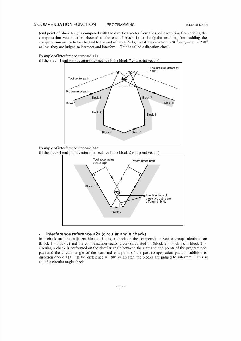
8/16/2019 Manual Operacion para FANUC
http://slidepdf.com/reader/full/manual-operacion-para-fanuc 196/435
5.COMPENSATION FUNCTION PROGRAMMING B-64304EN-1/01
- 178 -
(end point of block N-1) is compared with the direction vector from the (point resulting from adding the
compensation vector to be checked to the end of block 1) to the (point resulting from adding the
compensation vector to be checked to the end of block N-1), and if the direction is 90o or greater or 270
o
or less, they are judged to intersect and interfere. This is called a direction check.
Example of interference standard <1>
(If the block 1 end-point vector intersects with the block 7 end-point vector)
Programmed path
The direction differs by180°.
Block 5
Block 6
Tool center path
Block 3
Block 1 Block 8
Block 2
Block 4
Block 7
Example of interference standard <1>
(If the block 1 end-point vector intersects with the block 2 end-point vector)
Programmed pathTool nose radiuscenter path
The directions of these two paths aredifferent (180°).
Block 1
Block 2
- Interference reference <2> (circular angle check)In a check on three adjacent blocks, that is, a check on the compensation vector group calculated on
(block 1 - block 2) and the compensation vector group calculated on (block 2 - block 3), if block 2 is
circular, a check is performed on the circular angle between the start and end points of the programmed
path and the circular angle of the start and end point of the post-compensation path, in addition to
direction check <1>. If the difference is 180o or greater, the blocks are judged to interfere. This is
called a circular angle check.
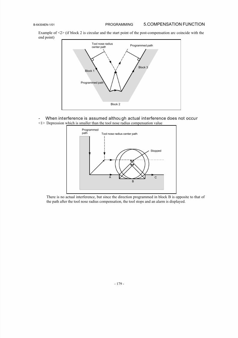
8/16/2019 Manual Operacion para FANUC
http://slidepdf.com/reader/full/manual-operacion-para-fanuc 197/435
B-64304EN-1/01 PROGRAMMING 5.COMPENSATION FUNCTION
- 179 -
Example of <2> (if block 2 is circular and the start point of the post-compensation arc coincide with the
end point)
Programmed pathTool nose radiuscenter path
Block 1
Block 2
Block 3
Programmed path
- When interference is assumed although actual interference does not occur<1> Depression which is smaller than the tool nose radius compensation value
Programmedpath Tool nose radius center path
A
B
C
Stopped
There is no actual interference, but since the direction programmed in block B is opposite to that of
the path after the tool nose radius compensation, the tool stops and an alarm is displayed.
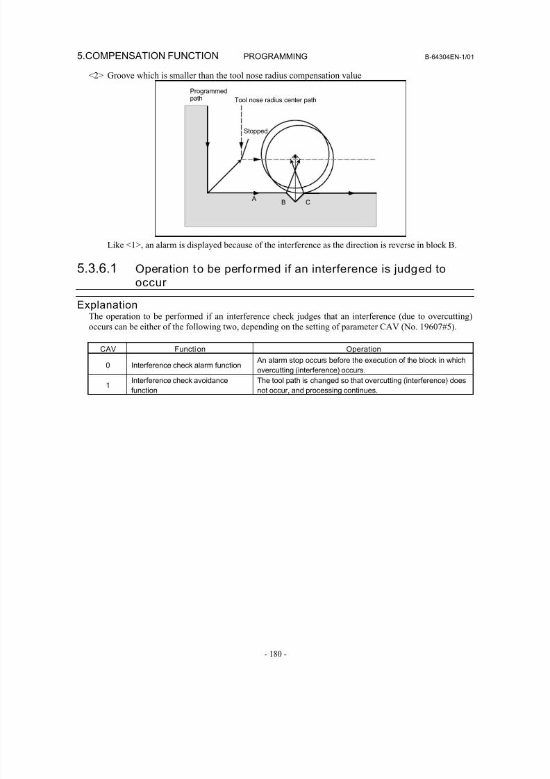
8/16/2019 Manual Operacion para FANUC
http://slidepdf.com/reader/full/manual-operacion-para-fanuc 198/435
5.COMPENSATION FUNCTION PROGRAMMING B-64304EN-1/01
- 180 -
<2> Groove which is smaller than the tool nose radius compensation value
B C
Stopped
Programmedpath Tool nose radius center path
A
Like <1>, an alarm is displayed because of the interference as the direction is reverse in block B.
5.3.6.1 Operation to be performed if an interference is judged to
occur
ExplanationThe operation to be performed if an interference check judges that an interference (due to overcutting)
occurs can be either of the following two, depending on the setting of parameter CAV (No. 19607#5).
CAV Function Operation
0 Interference check alarm function
An alarm stop occurs before the execution of the block in which
overcutting (interference) occurs.
1Interference check avoidance
function
The tool path is changed so that overcutting (interference) does
not occur, and processing continues.
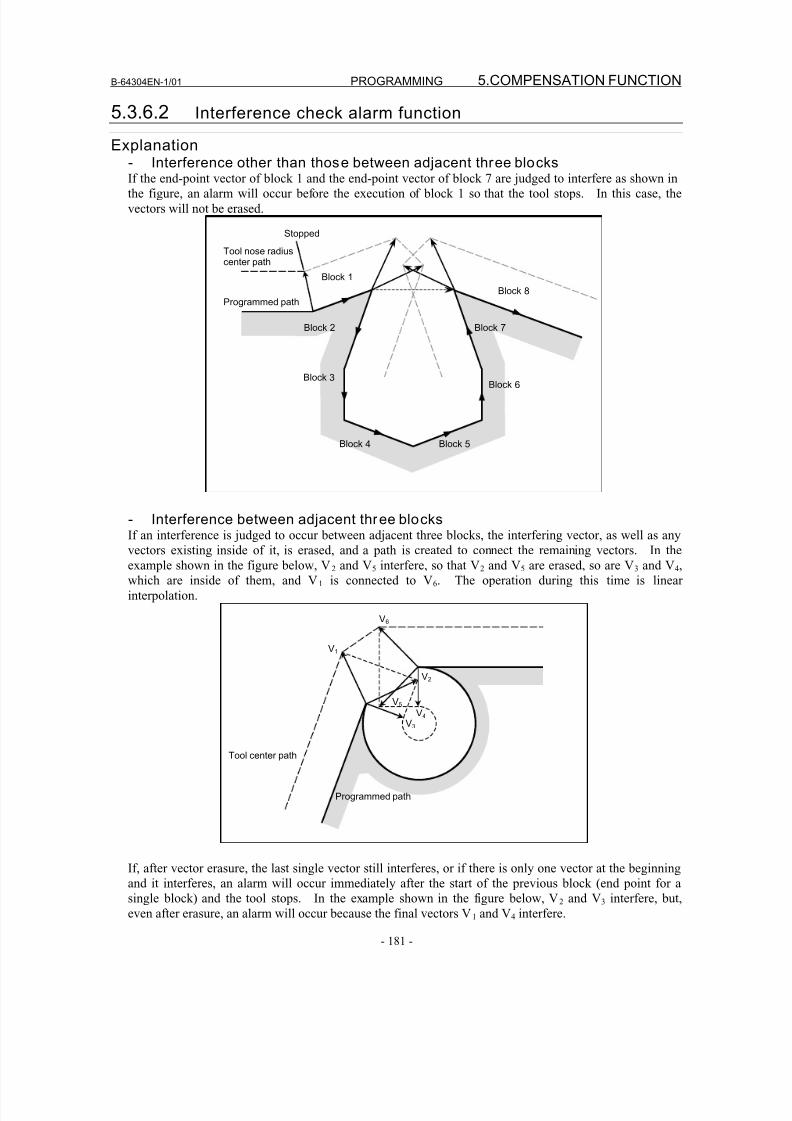
8/16/2019 Manual Operacion para FANUC
http://slidepdf.com/reader/full/manual-operacion-para-fanuc 199/435
B-64304EN-1/01 PROGRAMMING 5.COMPENSATION FUNCTION
- 181 -
5.3.6.2 Interference check alarm function
Explanation- Interference other than those between adjacent three blocks
If the end-point vector of block 1 and the end-point vector of block 7 are judged to interfere as shown inthe figure, an alarm will occur before the execution of block 1 so that the tool stops. In this case, the
vectors will not be erased.
Block 8
Block 3
Block 4 Block 5
Block 6
Block 2
Stopped
Tool nose radiuscenter path
Programmed path
Block 1
Block 7
- Interference between adjacent three blocksIf an interference is judged to occur between adjacent three blocks, the interfering vector, as well as any
vectors existing inside of it, is erased, and a path is created to connect the remaining vectors. In the
example shown in the figure below, V2 and V5 interfere, so that V2 and V5 are erased, so are V3 and V4,
which are inside of them, and V1 is connected to V6. The operation during this time is linear
interpolation.
Tool center path
Programmed path
V4
V2
V3
V1
V5
V6
If, after vector erasure, the last single vector still interferes, or if there is only one vector at the beginning
and it interferes, an alarm will occur immediately after the start of the previous block (end point for asingle block) and the tool stops. In the example shown in the figure below, V2 and V3 interfere, but,
even after erasure, an alarm will occur because the final vectors V1 and V4 interfere.
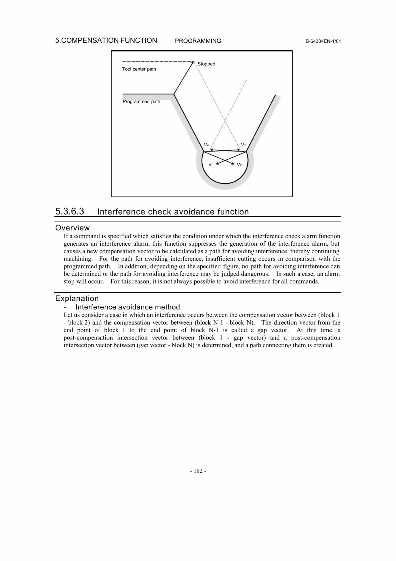
8/16/2019 Manual Operacion para FANUC
http://slidepdf.com/reader/full/manual-operacion-para-fanuc 200/435
5.COMPENSATION FUNCTION PROGRAMMING B-64304EN-1/01
- 182 -
StoppedTool center path
V4 V1
V3 V2
Programmed path
5.3.6.3 Interference check avoidance function
OverviewIf a command is specified which satisfies the condition under which the interference check alarm function
generates an interference alarm, this function suppresses the generation of the interference alarm, but
causes a new compensation vector to be calculated as a path for avoiding interference, thereby continuing
machining. For the path for avoiding interference, insufficient cutting occurs in comparison with the
programmed path. In addition, depending on the specified figure, no path for avoiding interference can be determined or the path for avoiding interference may be judged dangerous. In such a case, an alarm
stop will occur. For this reason, it is not always possible to avoid interference for all commands.
Explanation- Interference avoidance methodLet us consider a case in which an interference occurs between the compensation vector between (block 1
- block 2) and the compensation vector between (block N-1 - block N). The direction vector from the
end point of block 1 to the end point of block N-1 is called a gap vector. At this time, a
post-compensation intersection vector between (block 1 - gap vector) and a post-compensation
intersection vector between (gap vector - block N) is determined, and a path connecting them is created.
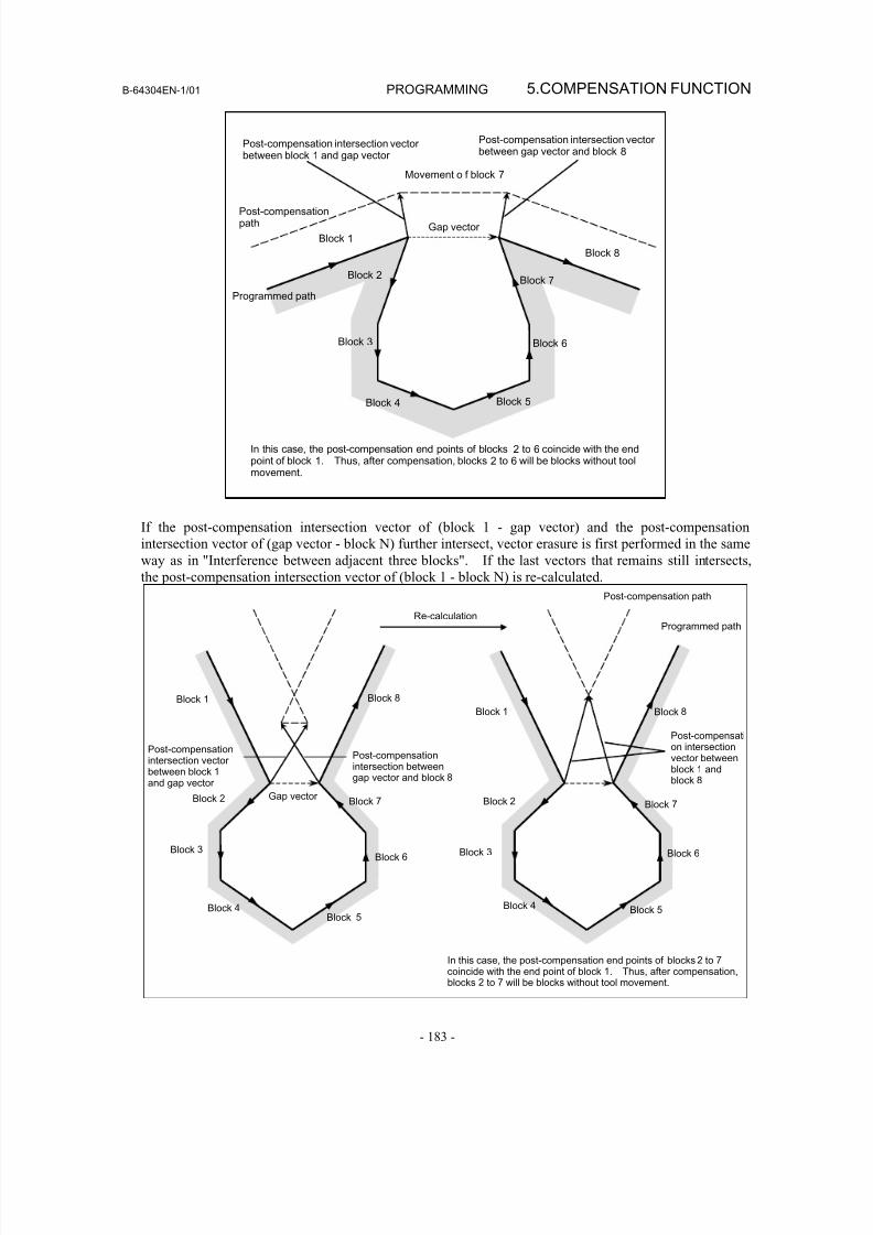
8/16/2019 Manual Operacion para FANUC
http://slidepdf.com/reader/full/manual-operacion-para-fanuc 201/435
B-64304EN-1/01 PROGRAMMING 5.COMPENSATION FUNCTION
- 183 -
Movement o f block 7
Post-compensation intersection vector between block 1 and gap vector
Post-compensation intersection vector between gap vector and block 8
Post-compensationpath
Programmed path
Block 1
Block 8
Block 2
Gap vector
Block 3 Block 6
Block 4 Block 5
In this case, the post-compensation end points of blocks 2 to 6 coincide with the endpoint of block 1. Thus, after compensation, blocks 2 to 6 will be blocks without toolmovement.
Block 7
If the post-compensation intersection vector of (block 1 - gap vector) and the post-compensation
intersection vector of (gap vector - block N) further intersect, vector erasure is first performed in the same
way as in "Interference between adjacent three blocks". If the last vectors that remains still intersects,
the post-compensation intersection vector of (block 1 - block N) is re-calculated.
In this case, the post-compensation end points of blocks 2 to 7
coincide with the end point of block 1. Thus, after compensation,blocks 2 to 7 will be blocks without tool movement.
Block 3
Post-compensationintersection vector
between block 1 and gap vector
Re-calculation
Block 8
Block 2
Block 3
Block 4 Block 5
Block 6
Block 7
Post-compensation path
Programmed path
Block 8
Block 7
Block 6
Post-compensationintersection between
gap vector and block 8
Block 1 Block 1
Post-compensation intersectionvector betweenblock 1 andblock 8
Gap vectorBlock 2
Block 4 Block
5
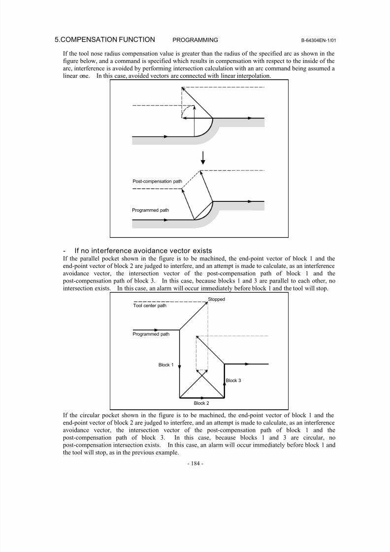
8/16/2019 Manual Operacion para FANUC
http://slidepdf.com/reader/full/manual-operacion-para-fanuc 202/435
5.COMPENSATION FUNCTION PROGRAMMING B-64304EN-1/01
- 184 -
If the tool nose radius compensation value is greater than the radius of the specified arc as shown in the
figure below, and a command is specified which results in compensation with respect to the inside of the
arc, interference is avoided by performing intersection calculation with an arc command being assumed a
linear one. In this case, avoided vectors are connected with linear interpolation.
Programmed path
Post-compensation path
- If no interference avoidance vector exists
If the parallel pocket shown in the figure is to be machined, the end-point vector of block 1 and theend-point vector of block 2 are judged to interfere, and an attempt is made to calculate, as an interference
avoidance vector, the intersection vector of the post-compensation path of block 1 and the
post-compensation path of block 3. In this case, because blocks 1 and 3 are parallel to each other, no
intersection exists. In this case, an alarm will occur immediately before block 1 and the tool will stop.
Block 1
Block 2
Block 3
Programmed path
Tool center path
Stopped
If the circular pocket shown in the figure is to be machined, the end-point vector of block 1 and the
end-point vector of block 2 are judged to interfere, and an attempt is made to calculate, as an interference
avoidance vector, the intersection vector of the post-compensation path of block 1 and the
post-compensation path of block 3. In this case, because blocks 1 and 3 are circular, no
post-compensation intersection exists. In this case, an alarm will occur immediately before block 1 and
the tool will stop, as in the previous example.
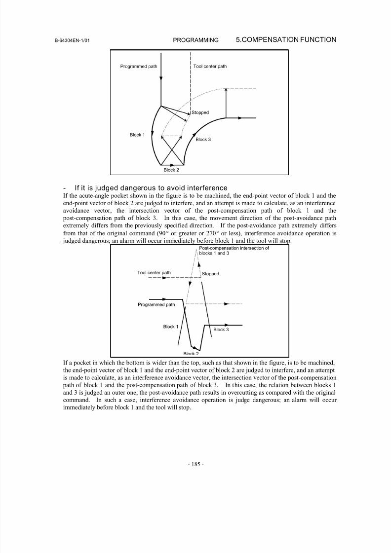
8/16/2019 Manual Operacion para FANUC
http://slidepdf.com/reader/full/manual-operacion-para-fanuc 203/435
B-64304EN-1/01 PROGRAMMING 5.COMPENSATION FUNCTION
- 185 -
Programmed path Tool center path
Block 1
Block 2
Block 3
Stopped
- If it is judged dangerous to avoid interferenceIf the acute-angle pocket shown in the figure is to be machined, the end-point vector of block 1 and the
end-point vector of block 2 are judged to interfere, and an attempt is made to calculate, as an interference
avoidance vector, the intersection vector of the post-compensation path of block 1 and the
post-compensation path of block 3. In this case, the movement direction of the post-avoidance path
extremely differs from the previously specified direction. If the post-avoidance path extremely differs
from that of the original command (90° or greater or 270° or less), interference avoidance operation is
judged dangerous; an alarm will occur immediately before block 1 and the tool will stop.
Tool center path
Programmed path
Block 1
Block 2
Block 3
Stopped
Post-compensation intersection of blocks 1 and 3
If a pocket in which the bottom is wider than the top, such as that shown in the figure, is to be machined,
the end-point vector of block 1 and the end-point vector of block 2 are judged to interfere, and an attempt
is made to calculate, as an interference avoidance vector, the intersection vector of the post-compensation
path of block 1 and the post-compensation path of block 3. In this case, the relation between blocks 1
and 3 is judged an outer one, the post-avoidance path results in overcutting as compared with the original
command. In such a case, interference avoidance operation is judge dangerous; an alarm will occur
immediately before block 1 and the tool will stop.
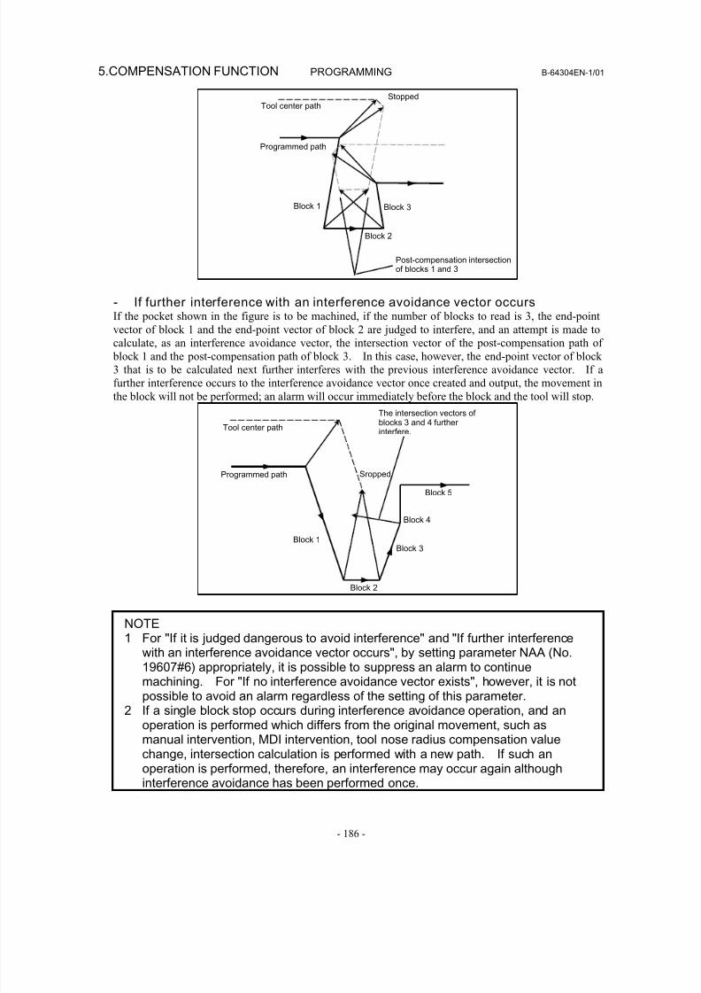
8/16/2019 Manual Operacion para FANUC
http://slidepdf.com/reader/full/manual-operacion-para-fanuc 204/435
5.COMPENSATION FUNCTION PROGRAMMING B-64304EN-1/01
- 186 -
Tool center path
Programmed path
Post-compensation intersectionof blocks 1 and 3
Block 1
Block 2
Block 3
Stopped
- If further interference with an interference avoidance vector occursIf the pocket shown in the figure is to be machined, if the number of blocks to read is 3, the end-point
vector of block 1 and the end-point vector of block 2 are judged to interfere, and an attempt is made to
calculate, as an interference avoidance vector, the intersection vector of the post-compensation path of
block 1 and the post-compensation path of block 3. In this case, however, the end-point vector of block
3 that is to be calculated next further interferes with the previous interference avoidance vector. If a
further interference occurs to the interference avoidance vector once created and output, the movement in
the block will not be performed; an alarm will occur immediately before the block and the tool will stop.
Tool center path
Programmed path
Block 1
Block 2
Block 3
Block 5
The intersection vectors of blocks 3 and 4 further interfere.
Sropped
Block 4
NOTE1 For "If it is judged dangerous to avoid interference" and "If further interference
with an interference avoidance vector occurs", by setting parameter NAA (No.19607#6) appropriately, it is possible to suppress an alarm to continuemachining. For "If no interference avoidance vector exists", however, it is notpossible to avoid an alarm regardless of the setting of this parameter.
2 If a single block stop occurs during interference avoidance operation, and anoperation is performed which differs from the original movement, such asmanual intervention, MDI intervention, tool nose radius compensation valuechange, intersection calculation is performed with a new path. If such anoperation is performed, therefore, an interference may occur again although
interference avoidance has been performed once.
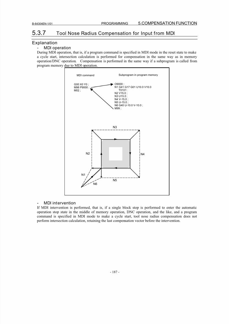
8/16/2019 Manual Operacion para FANUC
http://slidepdf.com/reader/full/manual-operacion-para-fanuc 205/435
B-64304EN-1/01 PROGRAMMING 5.COMPENSATION FUNCTION
- 187 -
5.3.7 Tool Nose Radius Compensation for Input f rom MDI
Explanation- MDI operationDuring MDI operation, that is, if a program command is specified in MDI mode in the reset state to make
a cycle start, intersection calculation is performed for compensation in the same way as in memory
operation/DNC operation. Compensation is performed in the same way if a subprogram is called from
program memory due to MDI operation.
Subprogram in program memory
O9000 ;N1 G41 G17 G01 U10.0 V10.0
T0101 ;N2 V15.0 ;N3 U15.0 ;N4 V-15.0 ;
N5 U-15.0 ;N6 G40 U-10.0 V-10.0 ;M99 ;
MDI command
G00 X0 Y0 ;M98 P9000 ;M02 ;
N6
N2
N3
N4
N5
N1
- MDI interventionIf MDI intervention is performed, that is, if a single block stop is performed to enter the automatic
operation stop state in the middle of memory operation, DNC operation, and the like, and a program
command is specified in MDI mode to make a cycle start, tool nose radius compensation does not
perform intersection calculation, retaining the last compensation vector before the intervention.
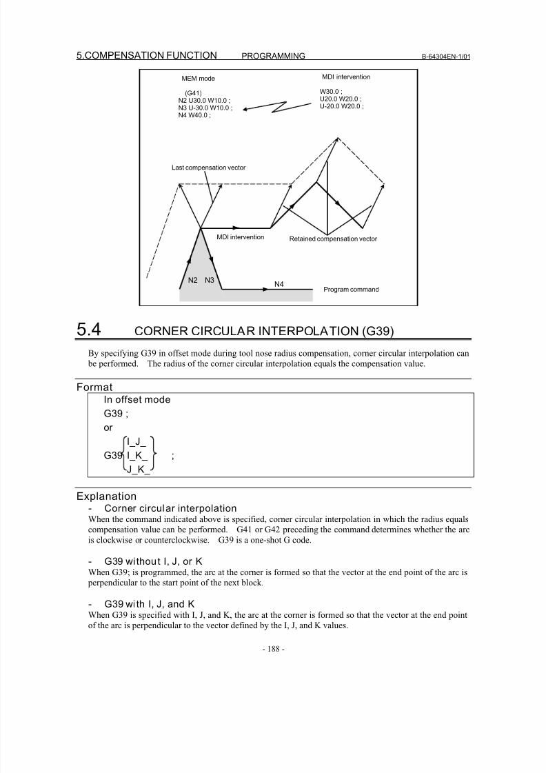
8/16/2019 Manual Operacion para FANUC
http://slidepdf.com/reader/full/manual-operacion-para-fanuc 206/435
5.COMPENSATION FUNCTION PROGRAMMING B-64304EN-1/01
- 188 -
MDI intervention
MDI intervention W30.0 ;U20.0 W20.0 ;U-20.0 W20.0 ;
MEM mode
(G41)N2 U30.0 W10.0 ;N3 U-30.0 W10.0 ;N4 W40.0 ;
N2 N3 N4
Program command
Last compensation vector
Retained compensation vector
5.4 CORNER CIRCULAR INTERPOLATION (G39)
By specifying G39 in offset mode during tool nose radius compensation, corner circular interpolation can
be performed. The radius of the corner circular interpolation equals the compensation value.
FormatIn offset mode
G39 ;
or
I_J_
G39 I_K_ ;
J_K_
Explanation- Corner circular interpolationWhen the command indicated above is specified, corner circular interpolation in which the radius equals
compensation value can be performed. G41 or G42 preceding the command determines whether the arc
is clockwise or counterclockwise. G39 is a one-shot G code.
- G39 without I, J, or KWhen G39; is programmed, the arc at the corner is formed so that the vector at the end point of the arc is
perpendicular to the start point of the next block.
- G39 wi th I, J, and KWhen G39 is specified with I, J, and K, the arc at the corner is formed so that the vector at the end point
of the arc is perpendicular to the vector defined by the I, J, and K values.
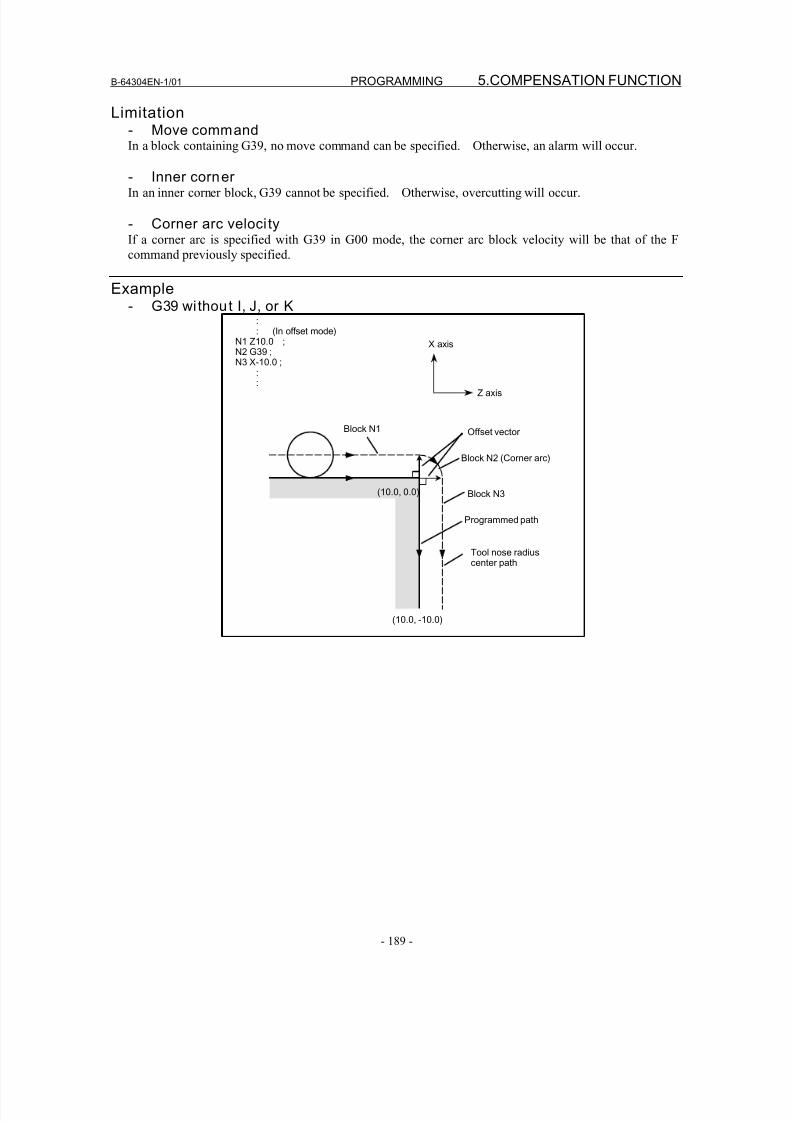
8/16/2019 Manual Operacion para FANUC
http://slidepdf.com/reader/full/manual-operacion-para-fanuc 207/435
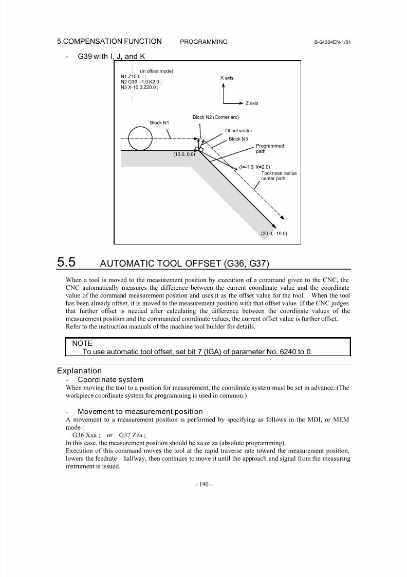
8/16/2019 Manual Operacion para FANUC
http://slidepdf.com/reader/full/manual-operacion-para-fanuc 208/435
5.COMPENSATION FUNCTION PROGRAMMING B-64304EN-1/01
- 190 -
- G39 wi th I, J, and K:: (In offset mode)
N1 Z10.0 ;N2 G39 I-1.0 K2.0 ;N3 X-10.0 Z20.0 ;
::
X axis
Z axis
Block N1
Offset vector
Block N2 (Corner arc)
Block N3
Tool nose radiuscenter path
(I=-1.0, K=2.0)
(20.0, -10.0)
Programmedpath
(10.0, 0.0)
5.5 AUTOMATIC TOOL OFFSET (G36, G37)
When a tool is moved to the measurement position by execution of a command given to the CNC, the
CNC automatically measures the difference between the current coordinate value and the coordinate
value of the command measurement position and uses it as the offset value for the tool. When the tool
has been already offset, it is moved to the measurement position with that offset value. If the CNC judges
that further offset is needed after calculating the difference between the coordinate values of the
measurement position and the commanded coordinate values, the current offset value is further offset.
Refer to the instruction manuals of the machine tool builder for details.
NOTETo use automatic tool offset, set bit 7 (IGA) of parameter No. 6240 to 0.
Explanation- Coordinate systemWhen moving the tool to a position for measurement, the coordinate system must be set in advance. (The
workpiece coordinate system for programming is used in common.)
- Movement to measurement positionA movement to a measurement position is performed by specifying as follows in the MDI, or MEM
mode :
G36 Xxa ; or G37 Zza ;
In this case, the measurement position should be xa or za (absolute programming).
Execution of this command moves the tool at the rapid traverse rate toward the measurement position,lowers the feedrate halfway, then continues to move it until the approach end signal from the measuring
instrument is issued.
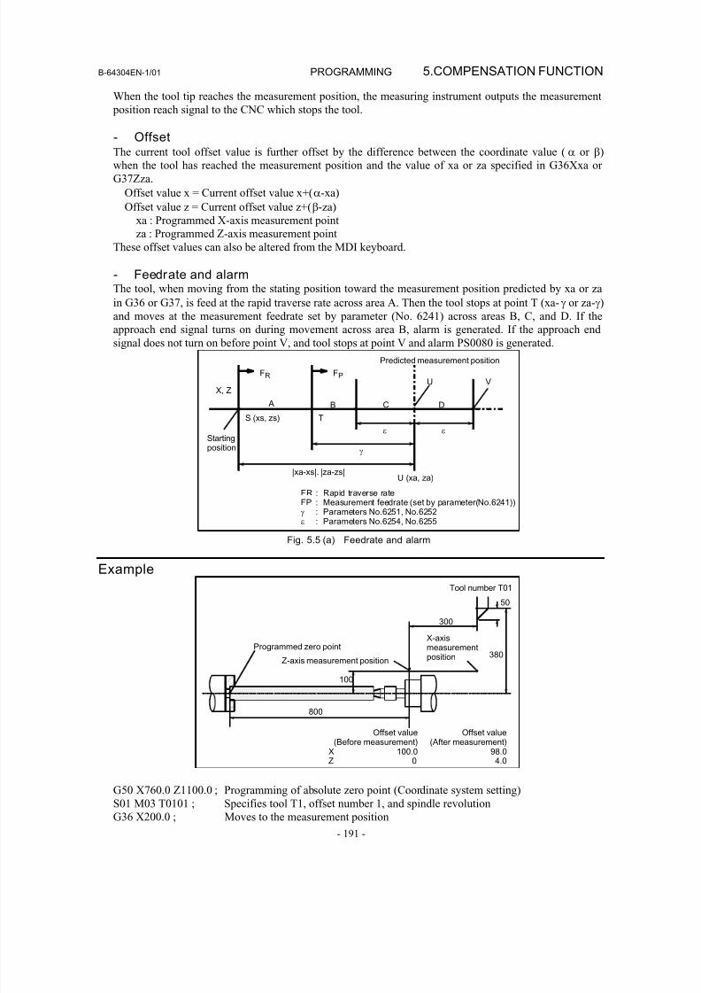
8/16/2019 Manual Operacion para FANUC
http://slidepdf.com/reader/full/manual-operacion-para-fanuc 209/435
B-64304EN-1/01 PROGRAMMING 5.COMPENSATION FUNCTION
- 191 -
When the tool tip reaches the measurement position, the measuring instrument outputs the measurement
position reach signal to the CNC which stops the tool.
- Offset
The current tool offset value is further offset by the difference between the coordinate value ( α or β)when the tool has reached the measurement position and the value of xa or za specified in G36Xxa or
G37Zza.
Offset value x = Current offset value x+(α-xa)
Offset value z = Current offset value z+(β-za)
xa : Programmed X-axis measurement point
za : Programmed Z-axis measurement point
These offset values can also be altered from the MDI keyboard.
- Feedrate and alarmThe tool, when moving from the stating position toward the measurement position predicted by xa or za
in G36 or G37, is feed at the rapid traverse rate across area A. Then the tool stops at point T (xa-γ or za-γ)
and moves at the measurement feedrate set by parameter (No. 6241) across areas B, C, and D. If the
approach end signal turns on during movement across area B, alarm is generated. If the approach end
signal does not turn on before point V, and tool stops at point V and alarm PS0080 is generated.
Startingposition
Predicted measurement position
ε ε
γ
TS (xs, zs)
X, Z
FR FPU V
A B C D
|xa-xs|. |za-zs|U (xa, za)
FR : Rapid traverse rateFP : Measurement feedrate (set by parameter(No.6241))γ : Parameters No.6251, No.6252ε : Parameters No.6254, No.6255
Fig. 5.5 (a) Feedrate and alarm
Example
800
100
380
50
300
Programmed zero point
Z-axis measurement position
X-axismeasurementposition
Tool number T01
Offset value Offset value(Before measurement) (After measurement)
X 100.0 98.0Z 0 4.0
G50 X760.0 Z1100.0 ; Programming of absolute zero point (Coordinate system setting)
S01 M03 T0101 ; Specifies tool T1, offset number 1, and spindle revolution
G36 X200.0 ; Moves to the measurement position
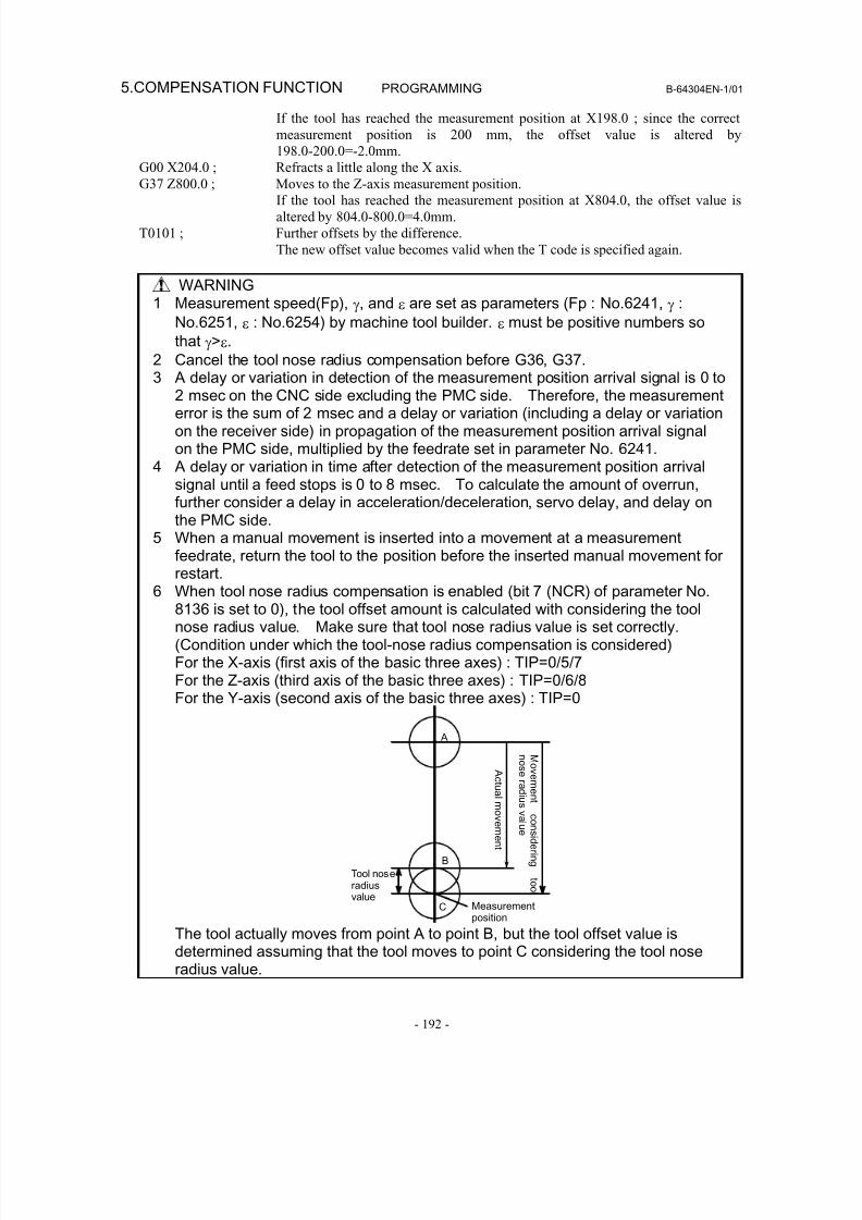
8/16/2019 Manual Operacion para FANUC
http://slidepdf.com/reader/full/manual-operacion-para-fanuc 210/435
5.COMPENSATION FUNCTION PROGRAMMING B-64304EN-1/01
- 192 -
If the tool has reached the measurement position at X198.0 ; since the correct
measurement position is 200 mm, the offset value is altered by
198.0-200.0=-2.0mm.
G00 X204.0 ; Refracts a little along the X axis.
G37 Z800.0 ; Moves to the Z-axis measurement position.
If the tool has reached the measurement position at X804.0, the offset value is
altered by 804.0-800.0=4.0mm.
T0101 ; Further offsets by the difference.
The new offset value becomes valid when the T code is specified again.
WARNING1 Measurement speed(Fp), γ, and ε are set as parameters (Fp : No.6241, γ :
No.6251, ε : No.6254) by machine tool builder. ε must be positive numbers sothat γ>ε.
2 Cancel the tool nose radius compensation before G36, G37.
3 A delay or variation in detection of the measurement position arrival signal is 0 to2 msec on the CNC side excluding the PMC side. Therefore, the measurementerror is the sum of 2 msec and a delay or variation (including a delay or variationon the receiver side) in propagation of the measurement position arrival signalon the PMC side, multiplied by the feedrate set in parameter No. 6241.
4 A delay or variation in time after detection of the measurement position arrivalsignal until a feed stops is 0 to 8 msec. To calculate the amount of overrun,further consider a delay in acceleration/deceleration, servo delay, and delay onthe PMC side.
5 When a manual movement is inserted into a movement at a measurementfeedrate, return the tool to the position before the inserted manual movement for
restart.6 When tool nose radius compensation is enabled (bit 7 (NCR) of parameter No.
8136 is set to 0), the tool offset amount is calculated with considering the toolnose radius value. Make sure that tool nose radius value is set correctly.(Condition under which the tool-nose radius compensation is considered)For the X-axis (first axis of the basic three axes) : TIP=0/5/7For the Z-axis (third axis of the basic three axes) : TIP=0/6/8For the Y-axis (second axis of the basic three axes) : TIP=0
A c t u al m ov em en t
M
ov em en t
c on s i d er i n g
t o ol
n
o s er a d i u s v al u e
Tool noseradiusvalue
Measurementposition
A
B
C
The tool actually moves from point A to point B, but the tool offset value is
determined assuming that the tool moves to point C considering the tool noseradius value.

8/16/2019 Manual Operacion para FANUC
http://slidepdf.com/reader/full/manual-operacion-para-fanuc 211/435
8/16/2019 Manual Operacion para FANUC
http://slidepdf.com/reader/full/manual-operacion-para-fanuc 212/435
PROGRAMMING B-64304EN-1/01
- 194 -
6. MEMORY OPERATIONUSING Series 10/11 FORMAT
6 MEMORY OPERATION USING Series 10/11FORMAT
By setting the setting-related parameter (bit 1 of parameter No. 0001), a program created in the Series
10/11 program format can be registered in memory for memory operation. Memory operation are
possible for the functions which use the same program format as that for the Series 10/11 as well as for
the following functions which use a different program format:
• Subprogram calling
• Canned cycle
• Multiple repetitive canned cycle
• Canned cycle for drilling
NOTE
Memory operation are possible only for the functions available in this CNC.
Chapter 6, "MEMORY OPERATION BY Series 10/11 FORMAT", consists of the following sections:
6.1 ADDRESSES AND SPECIFIABLE VALUE RANGE FOR Series 10/11 PROGRAM FORMAT194
6.2 SUBPROGRAM CALLING.............................................................................................................194
6.3 CANNED CYCLE............................................................................................................................195
6.4 MULTIPLE REPETITIVE CANNED CYCLE................................................................................211
6.5 CANNED CYCLE FOR DRILLING ...............................................................................................245
6.1 ADDRESSES AND SPECIFIABLE VALUE RANGE FORSeries 10/11 PROGRAM FORMAT
Some addresses which cannot be used for the this CNC can be used in the Series 10/11 program format.
The specifiable value range for the Series 10/11 program format is basically the same as that for the this
CNC. Sections II-6.2 to II-6.5 describe the addresses with a different specifiable value range. If a value
out of the specifiable value range is specified, an alarm is issued.
6.2 SUBPROGRAM CALLING
FormatM98 Pxxxx Lyyyy ;
P : Subprogram number
L : Repetition count
Explanation- AddressAddress L cannot be used in this CNC tape format but can be used in the Series 10/11 format.
- Subprogram numberThe specifiable value range is the same as that for this CNC (1 to 9999).
If a value of more than four digits is specified, the last four digits are assumed as the subprogram number.
8/16/2019 Manual Operacion para FANUC
http://slidepdf.com/reader/full/manual-operacion-para-fanuc 213/435
B-64304EN-1/01 PROGRAMMING
- 195 -
6.MEMORY OPERATIONUSING Series 10/11 FORMAT
- Repetition countThe repetition count L can be specified in the range from 1 to 9999. If no repetition count is specified, 1
is assumed.
6.3 CANNED CYCLE
ExplanationThere are three canned cycles : the outer diameter/internal diameter cutting canned cycle (G90), the
threading canned cycle (G92), and the end face turning canned cycle (G94).
NOTE1 Explanatory figures in this section use the ZX plane as the selected plane,
diameter programming for the X-axis, and radius programming for the Z-axis.When radius programming is used for the X-axis, change U/2 to U and X/2 to X.
2 A canned cycle can be performed on any plane (including parallel axes for planedefinition). When G code system A is used, however, U, V, and W cannot beset as a parallel axis.
3 The direction of the length means the direction of the first axis on the plane asfollows:ZX plane: Z-axis directionYZ plane: Y-axis directionXY plane: X-axis direction
4 The direction of the end face means the direction of the second axis on theplane as follows:ZX plane: X-axis direction
YZ plane: Z-axis directionXY plane: Y-axis direction
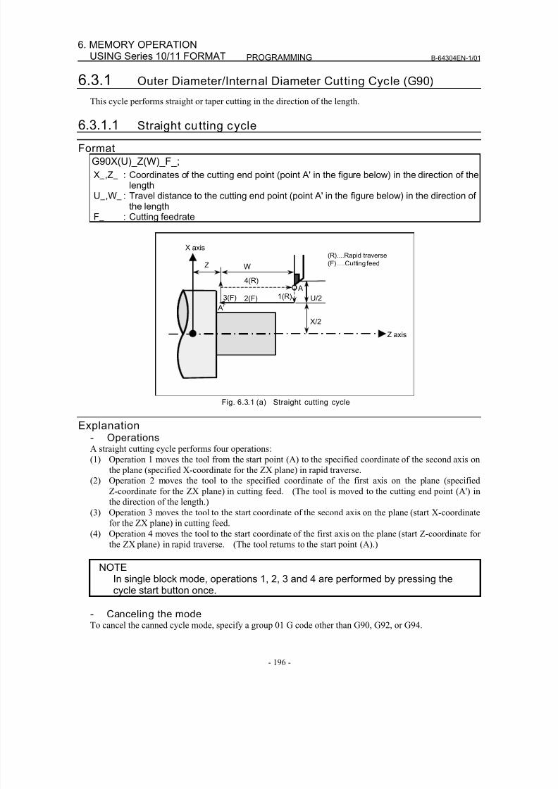
8/16/2019 Manual Operacion para FANUC
http://slidepdf.com/reader/full/manual-operacion-para-fanuc 214/435
PROGRAMMING B-64304EN-1/01
- 196 -
6. MEMORY OPERATIONUSING Series 10/11 FORMAT
6.3.1 Outer Diameter/Internal Diameter Cutting Cycle (G90)
This cycle performs straight or taper cutting in the direction of the length.
6.3.1.1 Straight cutting cycle
FormatG90X(U)_Z(W)_F_;
X_,Z_ : Coordinates of the cutting end point (point A' in the figure below) in the direction of thelength
U_,W_ : Travel distance to the cutting end point (point A' in the figure below) in the direction ofthe length
F_ : Cutting feedrate
X/2
X axis
Z axis
2(F)3(F) 1(R)
4(R)
Z W
U/2
A’
A
(R)....Rapid traverse
(F) ....Cutting feed
Fig. 6.3.1 (a) Straight cutting cycle
Explanation- OperationsA straight cutting cycle performs four operations:
(1) Operation 1 moves the tool from the start point (A) to the specified coordinate of the second axis on
the plane (specified X-coordinate for the ZX plane) in rapid traverse.
(2) Operation 2 moves the tool to the specified coordinate of the first axis on the plane (specified
Z-coordinate for the ZX plane) in cutting feed. (The tool is moved to the cutting end point (A') inthe direction of the length.)
(3) Operation 3 moves the tool to the start coordinate of the second axis on the plane (start X-coordinate
for the ZX plane) in cutting feed.
(4) Operation 4 moves the tool to the start coordinate of the first axis on the plane (start Z-coordinate for
the ZX plane) in rapid traverse. (The tool returns to the start point (A).)
NOTEIn single block mode, operations 1, 2, 3 and 4 are performed by pressing thecycle start button once.
- Canceling the modeTo cancel the canned cycle mode, specify a group 01 G code other than G90, G92, or G94.
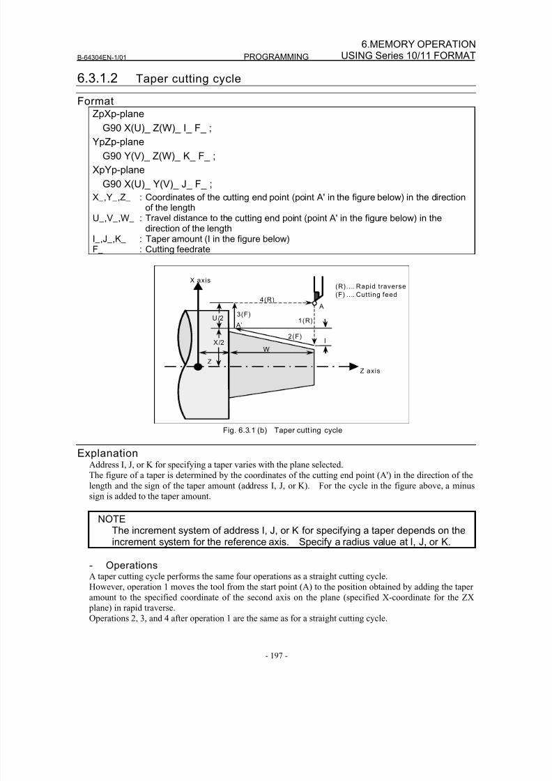
8/16/2019 Manual Operacion para FANUC
http://slidepdf.com/reader/full/manual-operacion-para-fanuc 215/435
B-64304EN-1/01 PROGRAMMING
- 197 -
6.MEMORY OPERATIONUSING Series 10/11 FORMAT
6.3.1.2 Taper cutting cycle
FormatZpXp-plane
G90 X(U)_ Z(W)_ I_ F_ ;
YpZp-plane
G90 Y(V)_ Z(W)_ K_ F_ ;
XpYp-plane
G90 X(U)_ Y(V)_ J_ F_ ;
X_,Y_,Z_ : Coordinates of the cutting end point (point A' in the figure below) in the directionof the length
U_,V_,W_ : Travel distance to the cutting end point (point A' in the figure below) in thedirection of the length
I_,J_,K_ : Taper amount (I in the figure below)F_ : Cutting feedrate
3(F)
X/2
4(R)
Z
U/2 1(R)
W
Z axis
2(F)I
X axis
A
A’
(R).... Rapid traverse
(F) .... Cutt ing feed
Fig. 6.3.1 (b) Taper cutt ing cycle
ExplanationAddress I, J, or K for specifying a taper varies with the plane selected.
The figure of a taper is determined by the coordinates of the cutting end point (A') in the direction of the
length and the sign of the taper amount (address I, J, or K). For the cycle in the figure above, a minus
sign is added to the taper amount.
NOTEThe increment system of address I, J, or K for specifying a taper depends on theincrement system for the reference axis. Specify a radius value at I, J, or K.
- OperationsA taper cutting cycle performs the same four operations as a straight cutting cycle.
However, operation 1 moves the tool from the start point (A) to the position obtained by adding the taper
amount to the specified coordinate of the second axis on the plane (specified X-coordinate for the ZX
plane) in rapid traverse.
Operations 2, 3, and 4 after operation 1 are the same as for a straight cutting cycle.
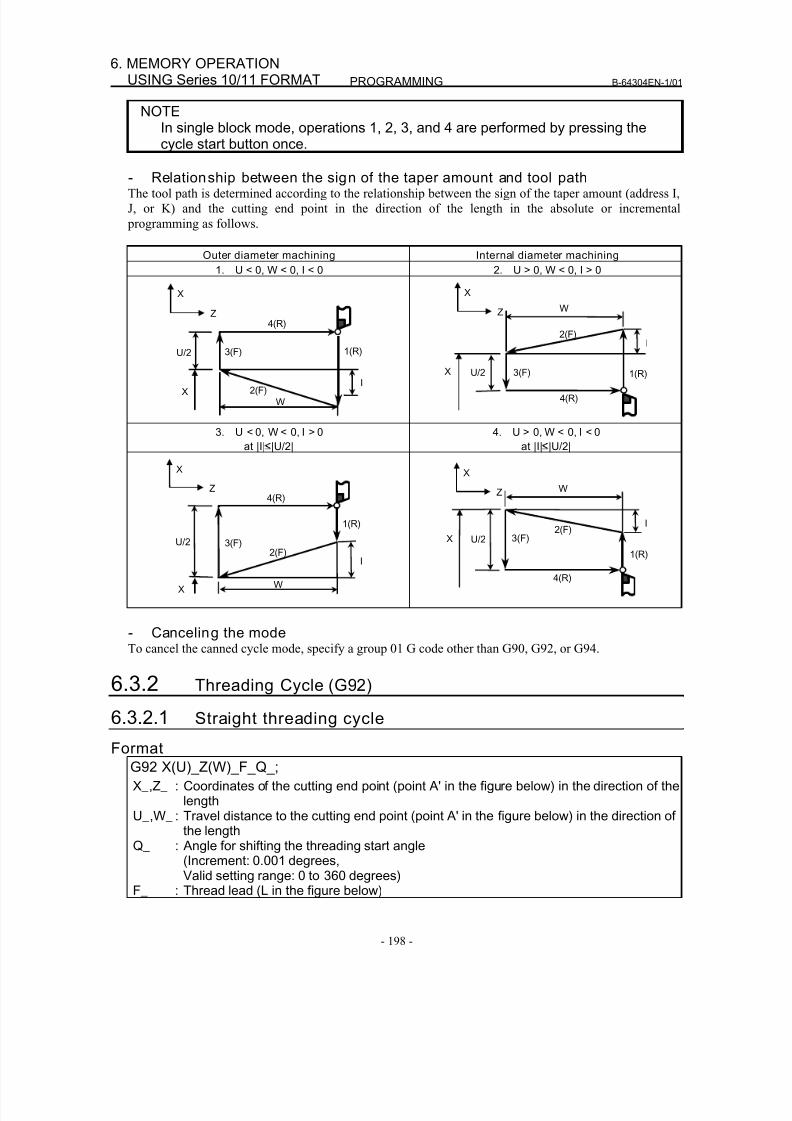
8/16/2019 Manual Operacion para FANUC
http://slidepdf.com/reader/full/manual-operacion-para-fanuc 216/435
PROGRAMMING B-64304EN-1/01
- 198 -
6. MEMORY OPERATIONUSING Series 10/11 FORMAT
NOTEIn single block mode, operations 1, 2, 3, and 4 are performed by pressing thecycle start button once.
- Relationship between the sign of the taper amount and tool pathThe tool path is determined according to the relationship between the sign of the taper amount (address I,
J, or K) and the cutting end point in the direction of the length in the absolute or incremental
programming as follows.
Outer diameter machining Internal diameter machining
1. U < 0, W < 0, I < 0 2. U > 0, W < 0, I > 0
X
Z
U/2 3(F)
4(R)
1(R)
2(F)
W
IX
X
Z
U/2 3(F)
4(R)
1(R)
2(F)
W
I
X
3. U < 0, W < 0, I > 0
at |I| |U/2|
4. U > 0, W < 0, I < 0
at |I| |U/2|
X
Z
U/2 3(F)
4(R)
1(R)
2(F)
W
I
X
X
Z
U/2 3(F)
4(R)
1(R)
2(F)
W
IX
- Canceling the modeTo cancel the canned cycle mode, specify a group 01 G code other than G90, G92, or G94.
6.3.2 Threading Cycle (G92)
6.3.2.1 Straight threading cycle
Format
G92 X(U)_Z(W)_F_Q_;
X_,Z_ : Coordinates of the cutting end point (point A' in the figure below) in the direction of thelength
U_,W_ : Travel distance to the cutting end point (point A' in the figure below) in the direction ofthe length
Q_ : Angle for shifting the threading start angle(Increment: 0.001 degrees,
Valid setting range: 0 to 360 degrees)F_ : Thread lead (L in the figure below)

8/16/2019 Manual Operacion para FANUC
http://slidepdf.com/reader/full/manual-operacion-para-fanuc 217/435
B-64304EN-1/01 PROGRAMMING
- 199 -
6.MEMORY OPERATIONUSING Series 10/11 FORMAT
X/2
X axis
Z axis
Z
L
1(R)2(F)3(R)
4(R)
Detailed chamfered thread
(The chamfered angle in the left figure is 45
degrees or less because of the delay in the
servo system.) r
W
Approx.45°
(R) ... Rapid traverse
(F)....Cutting feed
A
A’
U/2
Fig. 6.3.2 (c) Straight threading
ExplanationThe ranges of thread leads and restrictions related to the spindle speed are the same as for threading with
G32.
- OperationsA straight threading cycle performs four operations:
(1) Operation 1 moves the tool from the start point (A) to the specified coordinate of the second axis on
the plane (specified X-coordinate for the ZX plane) in rapid traverse.
(2) Operation 2 moves the tool to the specified coordinate of the first axis on the plane (specifiedZ-coordinate for the ZX plane) in cutting feed. At this time, thread chamfering is performed.
(3) Operation 3 moves the tool to the start coordinate of the second axis on the plane (start X-coordinate
for the ZX plane) in rapid traverse. (Retraction after chamfering)
(4) Operation 4 moves the tool to the start coordinate of the first axis on the plane (start Z-coordinate for
the ZX plane) in rapid traverse. (The tool returns to the start point (A).)
CAUTIONNotes on this threading are the same as in threading in G32. However, a stopby feed hold is as follows; Stop after completion of path 3 of threading cycle.
NOTEIn the single block mode, operations 1, 2, 3, and 4 are performed by pressingcycle start button once.
- Canceling the modeTo cancel the canned cycle mode, specify a group 01 G code other than G90, G92, or G94.
- Acceleration/deceleration for threading after interpolationAcceleration/deceleration for threading after interpolation is acceleration/deceleration of exponential
interpolation type. By setting bit 5 (THLx) of parameter No. 1610, the same acceleration/deceleration as
for cutting feed can be selected. (The settings of bit 0 (CTLx) of parameter No. 1610 are followed.)
However, as a time constant and FL feedrate, the settings of parameter No. 1626 and No. 1627 for the
threading cycle are used.
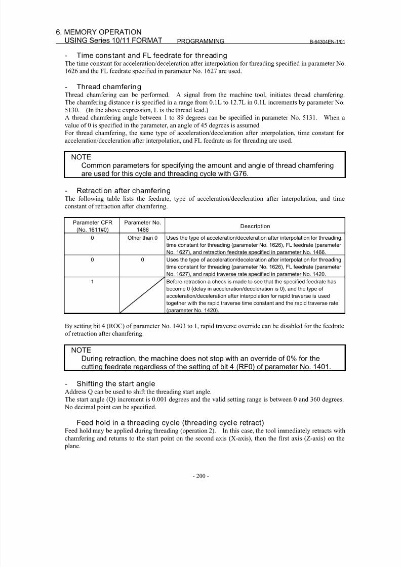
8/16/2019 Manual Operacion para FANUC
http://slidepdf.com/reader/full/manual-operacion-para-fanuc 218/435
PROGRAMMING B-64304EN-1/01
- 200 -
6. MEMORY OPERATIONUSING Series 10/11 FORMAT
- Time constant and FL feedrate for threadingThe time constant for acceleration/deceleration after interpolation for threading specified in parameter No.
1626 and the FL feedrate specified in parameter No. 1627 are used.
- Thread chamferingThread chamfering can be performed. A signal from the machine tool, initiates thread chamfering.
The chamfering distance r is specified in a range from 0.1L to 12.7L in 0.1L increments by parameter No.
5130. (In the above expression, L is the thread lead.)
A thread chamfering angle between 1 to 89 degrees can be specified in parameter No. 5131. When a
value of 0 is specified in the parameter, an angle of 45 degrees is assumed.
For thread chamfering, the same type of acceleration/deceleration after interpolation, time constant for
acceleration/deceleration after interpolation, and FL feedrate as for threading are used.
NOTECommon parameters for specifying the amount and angle of thread chamferingare used for this cycle and threading cycle with G76.
- Retraction after chamferingThe following table lists the feedrate, type of acceleration/deceleration after interpolation, and time
constant of retraction after chamfering.
Parameter CFR
(No. 1611#0)
Parameter No.
1466Description
0 Other than 0 Uses the type of acceleration/deceleration after interpolation for threading,
time constant for threading (parameter No. 1626), FL feedrate (parameter
No. 1627), and retraction feedrate specified in parameter No. 1466.
0 0 Uses the type of acceleration/deceleration after interpolation for threading,
time constant for threading (parameter No. 1626), FL feedrate (parameterNo. 1627), and rapid traverse rate specified in parameter No. 1420.
1 Before retraction a check is made to see that the specified feedrate has
become 0 (delay in acceleration/deceleration is 0), and the type of
acceleration/deceleration after interpolation for rapid traverse is used
together with the rapid traverse time constant and the rapid traverse rate
(parameter No. 1420).
By setting bit 4 (ROC) of parameter No. 1403 to 1, rapid traverse override can be disabled for the feedrate
of retraction after chamfering.
NOTE
During retraction, the machine does not stop with an override of 0% for thecutting feedrate regardless of the setting of bit 4 (RF0) of parameter No. 1401.
- Shifting the start angleAddress Q can be used to shift the threading start angle.
The start angle (Q) increment is 0.001 degrees and the valid setting range is between 0 and 360 degrees.
No decimal point can be specified.
Feed hold in a threading cycle (threading cycle retract)Feed hold may be applied during threading (operation 2). In this case, the tool immediately retracts with
chamfering and returns to the start point on the second axis (X-axis), then the first axis (Z-axis) on the
plane.
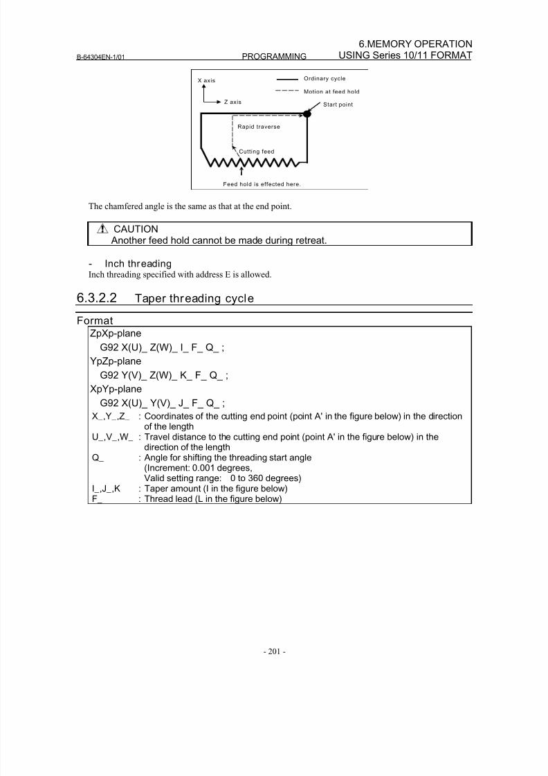
8/16/2019 Manual Operacion para FANUC
http://slidepdf.com/reader/full/manual-operacion-para-fanuc 219/435
B-64304EN-1/01 PROGRAMMING
- 201 -
6.MEMORY OPERATIONUSING Series 10/11 FORMAT
Feed hold is effected here.
Start point
Ordinary cycle
Rapid traverse
Motion at feed hold
X axis
Z axis
Cutt ing feed
The chamfered angle is the same as that at the end point.
CAUTION
Another feed hold cannot be made during retreat.
- Inch threadingInch threading specified with address E is allowed.
6.3.2.2 Taper threading cycle
FormatZpXp-plane
G92 X(U)_ Z(W)_ I_ F_ Q_ ;
YpZp-planeG92 Y(V)_ Z(W)_ K_ F_ Q_ ;
XpYp-plane
G92 X(U)_ Y(V)_ J_ F_ Q_ ;
X_,Y_,Z_ : Coordinates of the cutting end point (point A' in the figure below) in the directionof the length
U_,V_,W_ : Travel distance to the cutting end point (point A' in the figure below) in thedirection of the length
Q_ : Angle for shifting the threading start angle(Increment: 0.001 degrees,Valid setting range: 0 to 360 degrees)
I_,J_,K : Taper amount (I in the figure below)F_ : Thread lead (L in the figure below)
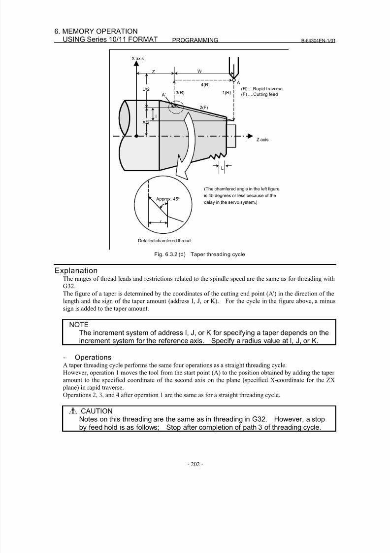
8/16/2019 Manual Operacion para FANUC
http://slidepdf.com/reader/full/manual-operacion-para-fanuc 220/435
PROGRAMMING B-64304EN-1/01
- 202 -
6. MEMORY OPERATIONUSING Series 10/11 FORMAT
Detailed chamfered thread
1(R)
Z axis
3(R)4(R)
2(F)
U/2
X/2
I
WZ
X axis
L
Approx. 45°
r
(The chamfered angle in the left figure
is 45 degrees or less because of the
delay in the servo system.)
(R)....Rapid traverse
(F) ....Cutting feed
A
A’
Fig. 6.3.2 (d) Taper threading cycle
ExplanationThe ranges of thread leads and restrictions related to the spindle speed are the same as for threading with
G32.
The figure of a taper is determined by the coordinates of the cutting end point (A') in the direction of the
length and the sign of the taper amount (address I, J, or K). For the cycle in the figure above, a minus
sign is added to the taper amount.
NOTEThe increment system of address I, J, or K for specifying a taper depends on theincrement system for the reference axis. Specify a radius value at I, J, or K.
- OperationsA taper threading cycle performs the same four operations as a straight threading cycle.
However, operation 1 moves the tool from the start point (A) to the position obtained by adding the taper
amount to the specified coordinate of the second axis on the plane (specified X-coordinate for the ZX
plane) in rapid traverse.
Operations 2, 3, and 4 after operation 1 are the same as for a straight threading cycle.
CAUTIONNotes on this threading are the same as in threading in G32. However, a stopby feed hold is as follows; Stop after completion of path 3 of threading cycle.
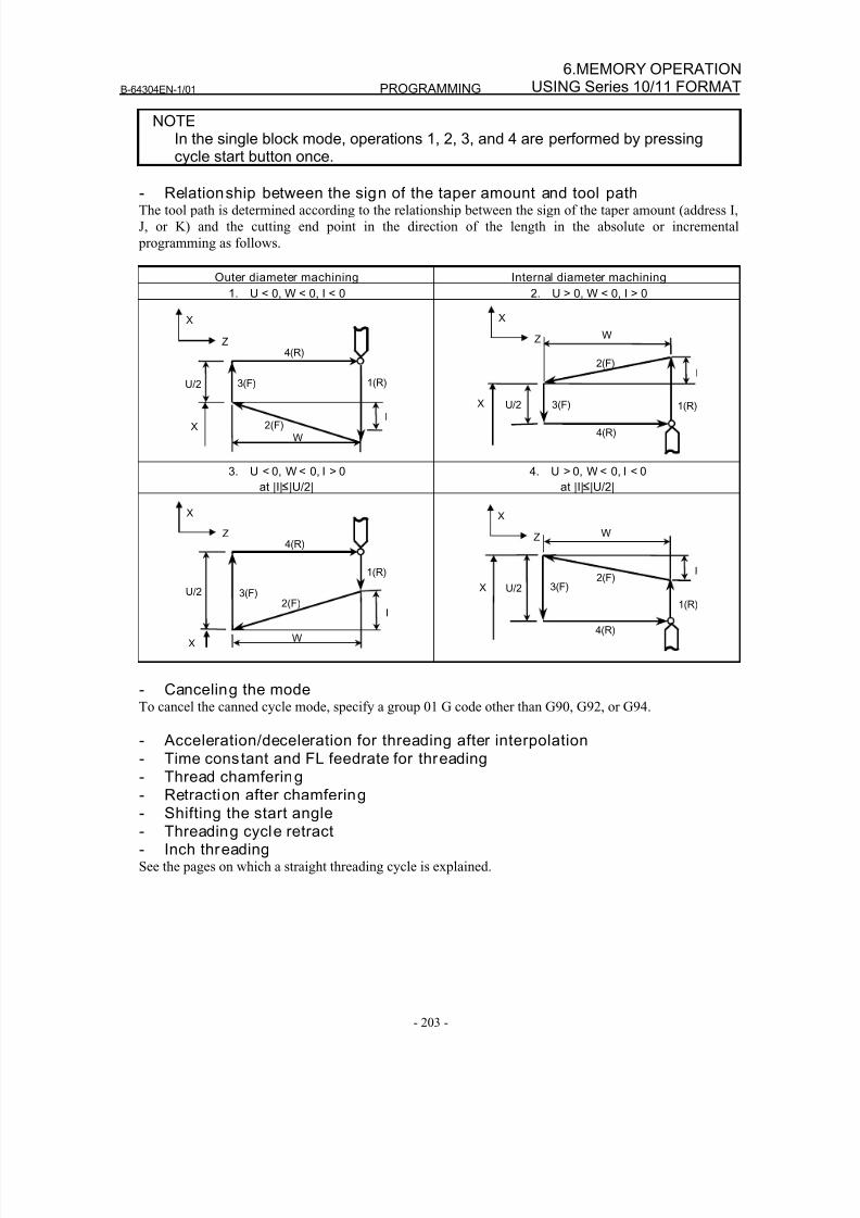
8/16/2019 Manual Operacion para FANUC
http://slidepdf.com/reader/full/manual-operacion-para-fanuc 221/435
B-64304EN-1/01 PROGRAMMING
- 203 -
6.MEMORY OPERATIONUSING Series 10/11 FORMAT
NOTEIn the single block mode, operations 1, 2, 3, and 4 are performed by pressingcycle start button once.
- Relationship between the sign of the taper amount and tool pathThe tool path is determined according to the relationship between the sign of the taper amount (address I,
J, or K) and the cutting end point in the direction of the length in the absolute or incremental
programming as follows.
Outer diameter machining Internal diameter machining
1. U < 0, W < 0, I < 0 2. U > 0, W < 0, I > 0
X
Z
U/2 3(F)
4(R)
1(R)
2(F)
W
IX
X
Z
U/2 3(F)
4(R)
1(R)
2(F)
W
I
X
3. U < 0, W < 0, I > 0
at |I|
|U/2|
4. U > 0, W < 0, I < 0
at |I|
|U/2|
X
Z
U/2 3(F)
4(R)
1(R)
2(F)
W
I
X
X
Z
U/2 3(F)
4(R)
1(R)
2(F)
W
IX
- Canceling the modeTo cancel the canned cycle mode, specify a group 01 G code other than G90, G92, or G94.
- Acceleration/deceleration for threading after interpolation
- Time constant and FL feedrate for threading- Thread chamfering- Retraction after chamfering- Shifting the start angle- Threading cycle retract- Inch threadingSee the pages on which a straight threading cycle is explained.
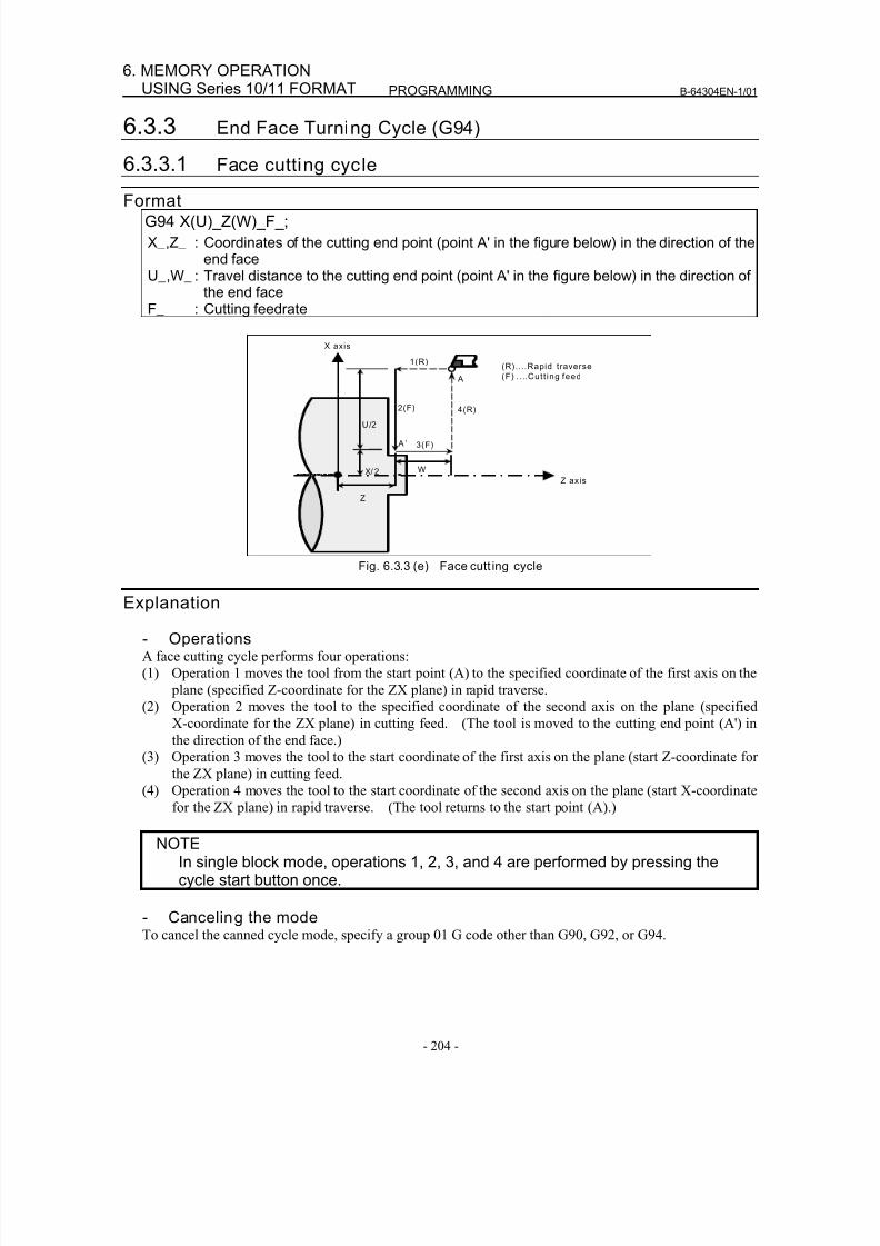
8/16/2019 Manual Operacion para FANUC
http://slidepdf.com/reader/full/manual-operacion-para-fanuc 222/435
PROGRAMMING B-64304EN-1/01
- 204 -
6. MEMORY OPERATIONUSING Series 10/11 FORMAT
6.3.3 End Face Turning Cycle (G94)
6.3.3.1 Face cutting cycle
FormatG94 X(U)_Z(W)_F_;
X_,Z_ : Coordinates of the cutting end point (point A' in the figure below) in the direction of theend face
U_,W_ : Travel distance to the cutting end point (point A' in the figure below) in the direction ofthe end face
F_ : Cutting feedrate
X axis
4(R)
X/ 2
3(F)
Z axis
1(R)
2(F)
Z
W
(R)....Rapid traverse
(F) . . ..Cutt ing feed
U/2
A
A ’
Fig. 6.3.3 (e) Face cutt ing cycle
Explanation
- OperationsA face cutting cycle performs four operations:
(1) Operation 1 moves the tool from the start point (A) to the specified coordinate of the first axis on the
plane (specified Z-coordinate for the ZX plane) in rapid traverse.
(2) Operation 2 moves the tool to the specified coordinate of the second axis on the plane (specified
X-coordinate for the ZX plane) in cutting feed. (The tool is moved to the cutting end point (A') in
the direction of the end face.)
(3) Operation 3 moves the tool to the start coordinate of the first axis on the plane (start Z-coordinate for
the ZX plane) in cutting feed.
(4) Operation 4 moves the tool to the start coordinate of the second axis on the plane (start X-coordinate
for the ZX plane) in rapid traverse. (The tool returns to the start point (A).)
NOTEIn single block mode, operations 1, 2, 3, and 4 are performed by pressing thecycle start button once.
- Canceling the modeTo cancel the canned cycle mode, specify a group 01 G code other than G90, G92, or G94.
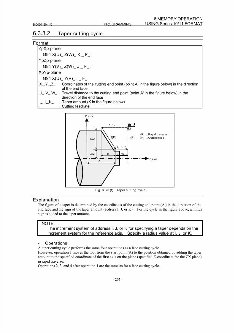
8/16/2019 Manual Operacion para FANUC
http://slidepdf.com/reader/full/manual-operacion-para-fanuc 223/435
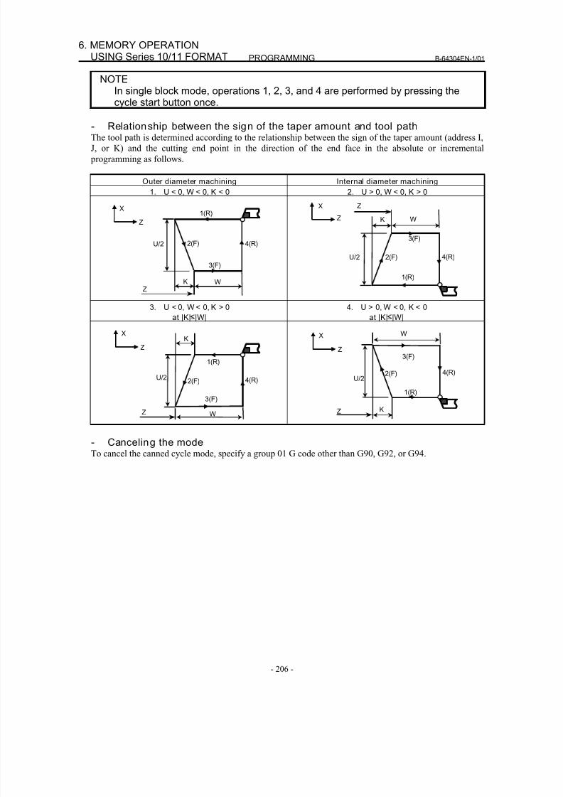
8/16/2019 Manual Operacion para FANUC
http://slidepdf.com/reader/full/manual-operacion-para-fanuc 224/435
PROGRAMMING B-64304EN-1/01
- 206 -
6. MEMORY OPERATIONUSING Series 10/11 FORMAT
NOTEIn single block mode, operations 1, 2, 3, and 4 are performed by pressing thecycle start button once.
- Relationship between the sign of the taper amount and tool pathThe tool path is determined according to the relationship between the sign of the taper amount (address I,
J, or K) and the cutting end point in the direction of the end face in the absolute or incremental
programming as follows.
Outer diameter machining Internal diameter machining
1. U < 0, W < 0, K < 0 2. U > 0, W < 0, K > 0
X1(R)
Z
U/2
3(F)
4(R)2(F)
WKZ
Z
U/2
3(F)
4(R)2(F)
WK
X
1(R)
Z
3. U < 0, W < 0, K > 0
at |K| |W|
4. U > 0, W < 0, K < 0
at |K| |W|
W
Z
U/2
3(F)
4(R)2(F)
KX
1(R)
Z
Z
X W
U/2
3(F)
4(R)2(F)
K
1(R)
Z
- Canceling the modeTo cancel the canned cycle mode, specify a group 01 G code other than G90, G92, or G94.
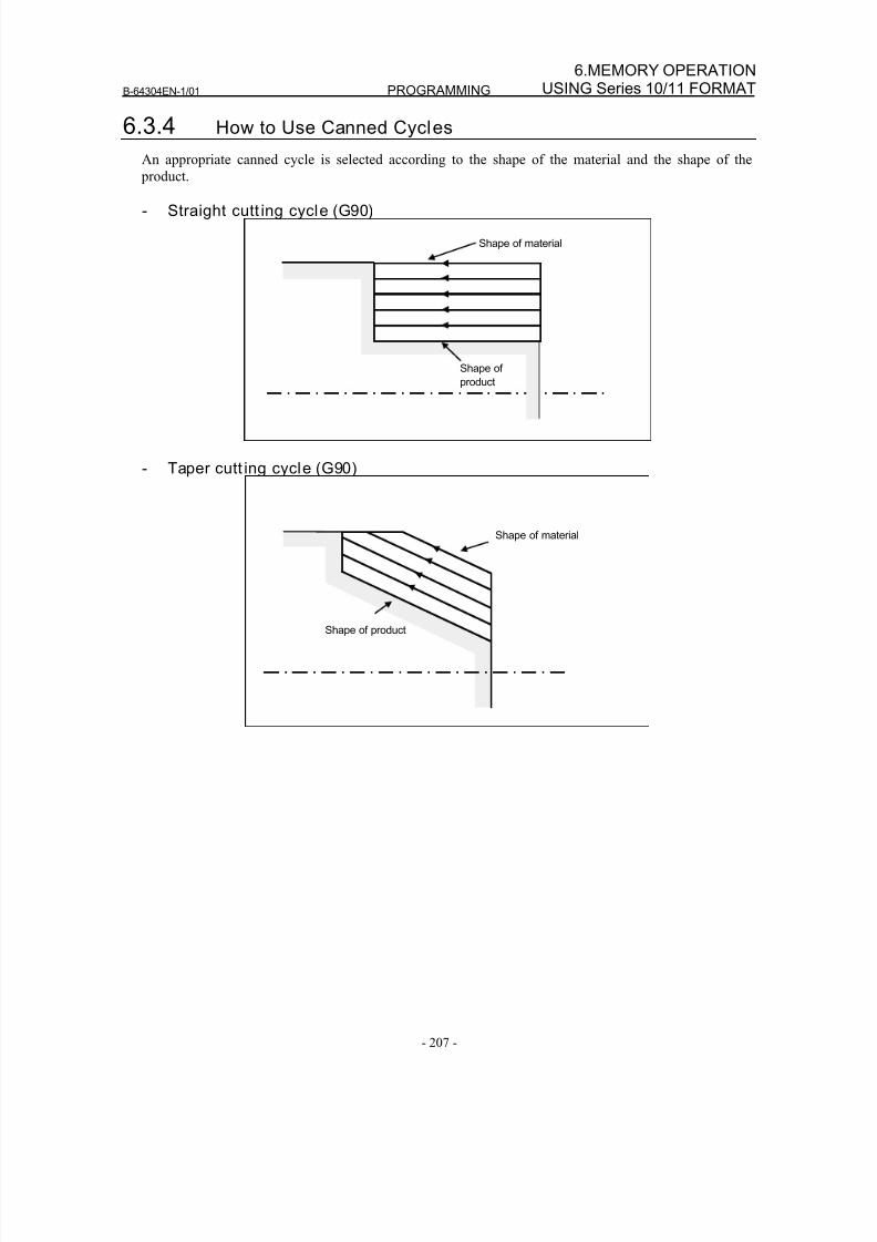
8/16/2019 Manual Operacion para FANUC
http://slidepdf.com/reader/full/manual-operacion-para-fanuc 225/435
B-64304EN-1/01 PROGRAMMING
- 207 -
6.MEMORY OPERATIONUSING Series 10/11 FORMAT
6.3.4 How to Use Canned Cycles
An appropriate canned cycle is selected according to the shape of the material and the shape of the
product.
- Straight cutt ing cycle (G90)
Shape of
product
Shape of material
- Taper cutt ing cycle (G90)
Shape of product
Shape of material
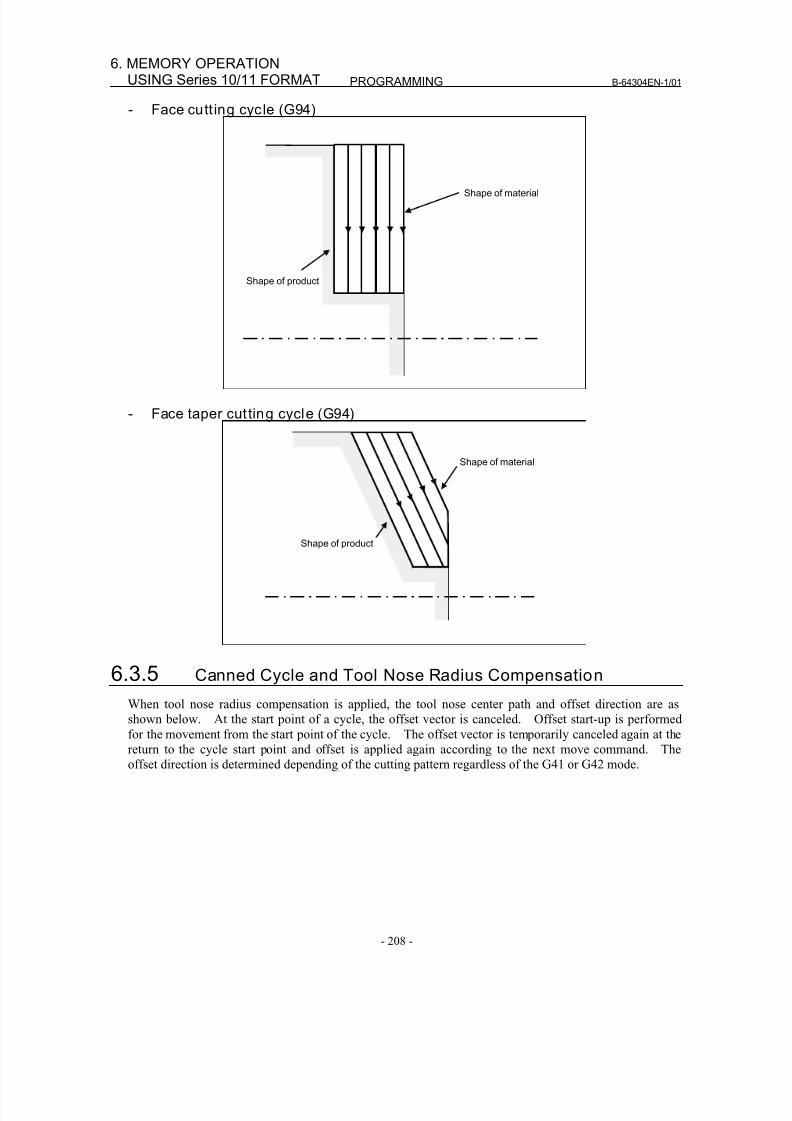
8/16/2019 Manual Operacion para FANUC
http://slidepdf.com/reader/full/manual-operacion-para-fanuc 226/435
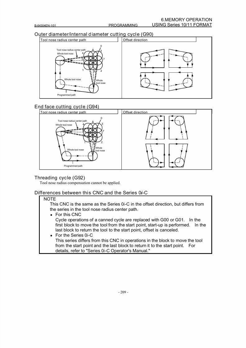
8/16/2019 Manual Operacion para FANUC
http://slidepdf.com/reader/full/manual-operacion-para-fanuc 227/435
B-64304EN-1/01 PROGRAMMING
- 209 -
6.MEMORY OPERATIONUSING Series 10/11 FORMAT
Outer diameter/internal d iameter cutt ing cycle (G90)Tool nose radius center path Offset direction
Whole tool nose
Tool nose radius center path
Programmed path
0
8
4
5 7
3
16 2
Wholetool nose
Whole tool nose
End face cutting cycle (G94)Tool nose radius center path Offset direction
Whole tool nose
Tool nose radius center path
Programmed path
0
84
5 7
3
1 62
Wholetool nose
Whole tool nose
Threading cyc le (G92)Tool nose radius compensation cannot be applied.
Differences between this CNC and the Series 0i-C
NOTEThis CNC is the same as the Series 0i-C in the offset direction, but differs from
the series in the tool nose radius center path.
• For this CNC
Cycle operations of a canned cycle are replaced with G00 or G01. In thefirst block to move the tool from the start point, start-up is performed. In thelast block to return the tool to the start point, offset is canceled.
• For the Series 0i-C
This series differs from this CNC in operations in the block to move the toolfrom the start point and the last block to return it to the start point. Fordetails, refer to "Series 0i-C Operator's Manual."
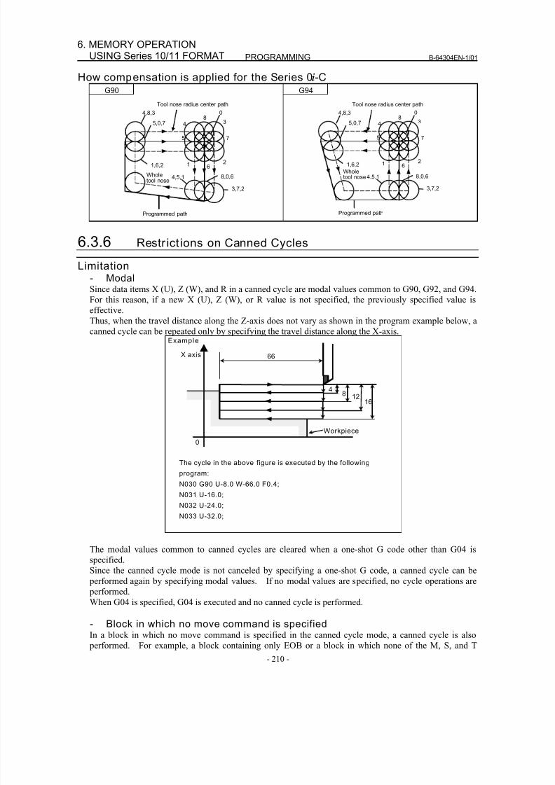
8/16/2019 Manual Operacion para FANUC
http://slidepdf.com/reader/full/manual-operacion-para-fanuc 228/435
8/16/2019 Manual Operacion para FANUC
http://slidepdf.com/reader/full/manual-operacion-para-fanuc 229/435
B-64304EN-1/01 PROGRAMMING
- 211 -
6.MEMORY OPERATIONUSING Series 10/11 FORMAT
codes, and move commands are specified is of this type of block. When an M, S, or T code is specified
in the canned cycle mode, the corresponding M, S, or T function is executed together with the canned
cycle. If this is inconvenient, specify a group 01 G code (G00 or G01) other than G90, G92, or G94 to
cancel the canned cycle mode, and specify an M, S, or T code, as in the program example below. After
the corresponding M, S, or T function has been executed, specify the canned cycle again.
Example
N003 T0101;
:
:
N010 G90 X20.0 Z10.0 F0.2;
N011 G00 T0202; ← Cancels the canned cycle mode.
N012 G90 X20.5 Z10.0;
- Plane selection command
Specify a plane selection command (G17, G18, or G19) before setting a canned cycle or specify it in the block in which the first canned cycle is specified.
If a plane selection command is specified in the canned cycle mode, the command is executed, but the
modal values common to canned cycles are cleared.
If an axis which is not on the selected plane is specified, alarm PS0330 is issued.
- Parallel axisWhen G code system A is used, U, V, and W cannot be specified as a parallel axis.
- ResetIf a reset operation is performed during execution of a canned cycle when any of the following states for
holding a modal G code of group 01 is set, the modal G code of group 01 is replaced with the G01 mode:• Reset state (bit 6 (CLR) of parameter No. 3402 = 0)
• Cleared state (bit 6 (CLR) of parameter No. 3402 = 1) and state where the modal G code of group 01
is held at reset time (bit 1 (C01) of parameter No. 3406 = 1)
Example of operation)
If a reset is made during execution of a canned cycle (X0 block) and the X20.Z1. command is
executed, linear interpolation (G01) is performed instead of the canned cycle.
6.4 MULTIPLE REPETITIVE CANNED CYCLE
The multiple repetitive canned cycle is canned cycles to make CNC programming easy. For instance,
the data of the finish workpiece shape describes the tool path for rough machining. And also, a cannedcycles for the threading is available.
NOTE1 Explanatory figures in this section use the ZX plane as the selected plane,
diameter programming for the X-axis, and radius programming for the Z-axis.When radius programming is used for the X-axis, change U/2 to U and X/2 to X.
2 A multiple repetitive canned cycle can be performed on any plane (includingparallel axes for plane definition). When G code system A is used, however, U,V, and W cannot be set as a parallel axis.
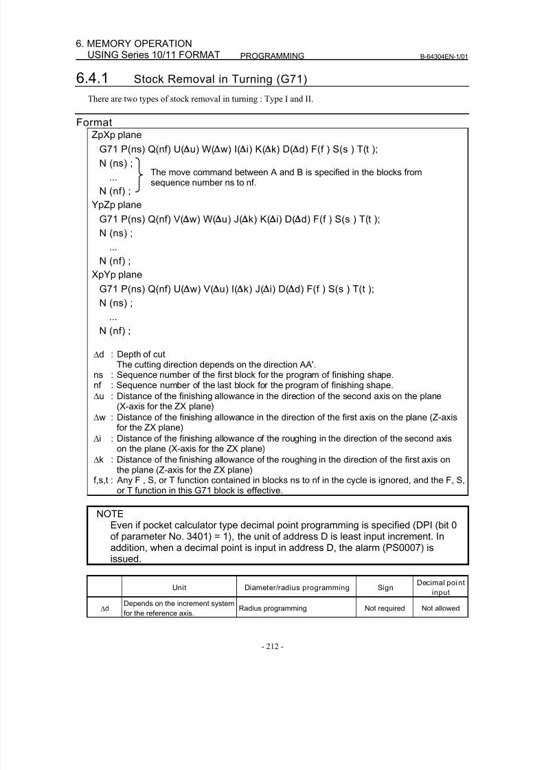
8/16/2019 Manual Operacion para FANUC
http://slidepdf.com/reader/full/manual-operacion-para-fanuc 230/435
PROGRAMMING B-64304EN-1/01
- 212 -
6. MEMORY OPERATIONUSING Series 10/11 FORMAT
6.4.1 Stock Removal in Turning (G71)
There are two types of stock removal in turning : Type I and II.
FormatZpXp plane
G71 P(ns) Q(nf) U( u) W( w) I( i) K( k) D( d) F(f ) S(s ) T(t );
N (ns) ;
...
N (nf) ;
YpZp plane
G71 P(ns) Q(nf) V( w) W( u) J( k) K( i) D( d) F(f ) S(s ) T(t );
N (ns) ;
...
N (nf) ;
XpYp plane
G71 P(ns) Q(nf) U( w) V( u) I( k) J( i) D( d) F(f ) S(s ) T(t );
N (ns) ;
...
N (nf) ;
Δd : Depth of cut
The cutting direction depends on the direction AA'.ns : Sequence number of the first block for the program of finishing shape.nf : Sequence number of the last block for the program of finishing shape.
Δu : Distance of the finishing allowance in the direction of the second axis on the plane(X-axis for the ZX plane)
Δw : Distance of the finishing allowance in the direction of the first axis on the plane (Z-axisfor the ZX plane)
Δi : Distance of the finishing allowance of the roughing in the direction of the second axison the plane (X-axis for the ZX plane)
Δk : Distance of the finishing allowance of the roughing in the direction of the first axis onthe plane (Z-axis for the ZX plane)
f,s,t : Any F , S, or T function contained in blocks ns to nf in the cycle is ignored, and the F, S,or T function in this G71 block is effective.
NOTEEven if pocket calculator type decimal point programming is specified (DPI (bit 0of parameter No. 3401) = 1), the unit of address D is least input increment. Inaddition, when a decimal point is input in address D, the alarm (PS0007) isissued.
Unit Diameter/radius programming SignDecimal point
input
Δd Depends on the increment systemfor the reference axis.
Radius programming Not required Not allowed
The move command between A and B is specified in the blocks fromsequence number ns to nf.
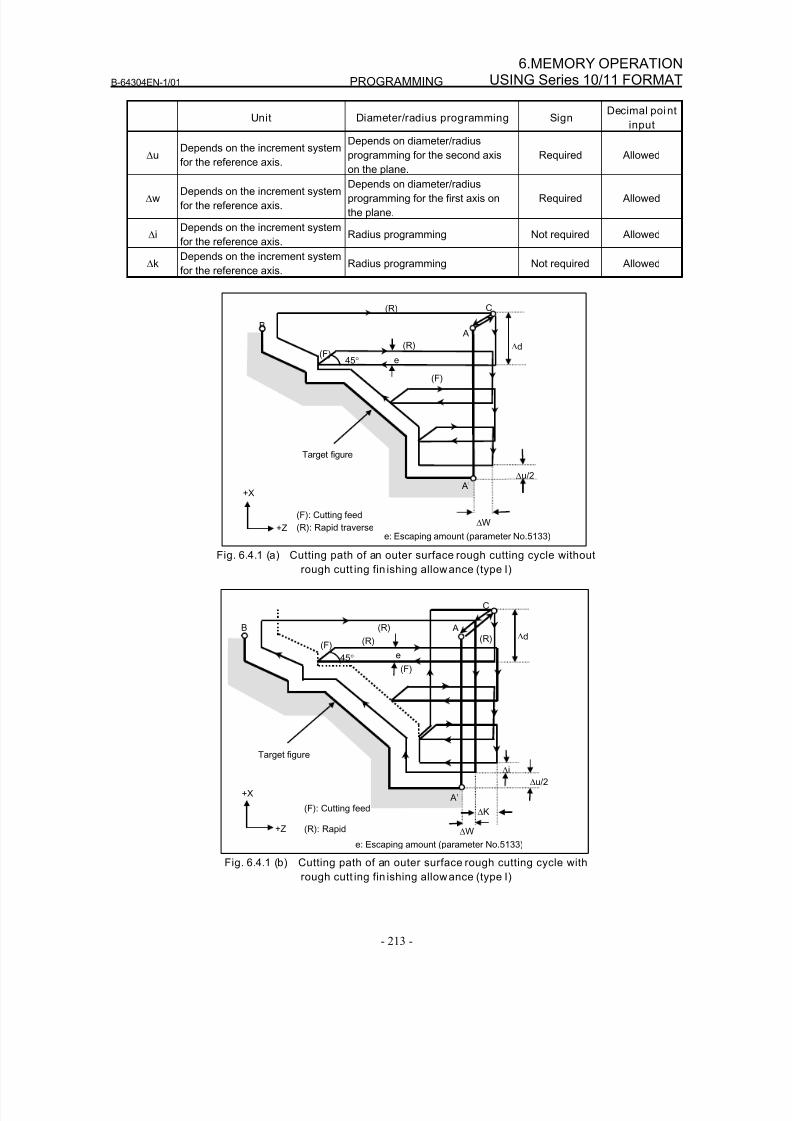
8/16/2019 Manual Operacion para FANUC
http://slidepdf.com/reader/full/manual-operacion-para-fanuc 231/435
B-64304EN-1/01 PROGRAMMING
- 213 -
6.MEMORY OPERATIONUSING Series 10/11 FORMAT
Unit Diameter/radius programming SignDecimal point
input
ΔuDepends on the increment system
for the reference axis.
Depends on diameter/radius
programming for the second axis
on the plane.
Required Allowed
ΔwDepends on the increment system
for the reference axis.
Depends on diameter/radius
programming for the first axis on
the plane.
Required Allowed
ΔiDepends on the increment system
for the reference axis.Radius programming Not required Allowed
ΔkDepends on the increment system
for the reference axis.Radius programming Not required Allowed
C
B
(R)
(R)
(F)
(F)
A
Δu/2
Δd
A’
ΔW
Target figure
45° e
(F): Cutting feed
(R): Rapid traverse
+X
+Ze: Escaping amount (parameter No.5133)
Fig. 6.4.1 (a) Cutting path of an outer surface rough cutting cycle without
rough cutt ing fin ishing allowance (type I)
C
B
(R)
(R)
(F)
(F)
A
Δu/2
Δd
A’
ΔW
Target figure
45° e
(F): Cutting feed
(R): Rapid
+X
+Z
(R)
ΔK
Δi
e: Escaping amount (parameter No.5133)
Fig. 6.4.1 (b) Cutting path of an outer surface rough cutting cycle with
rough cutt ing fin ishing allowance (type I)
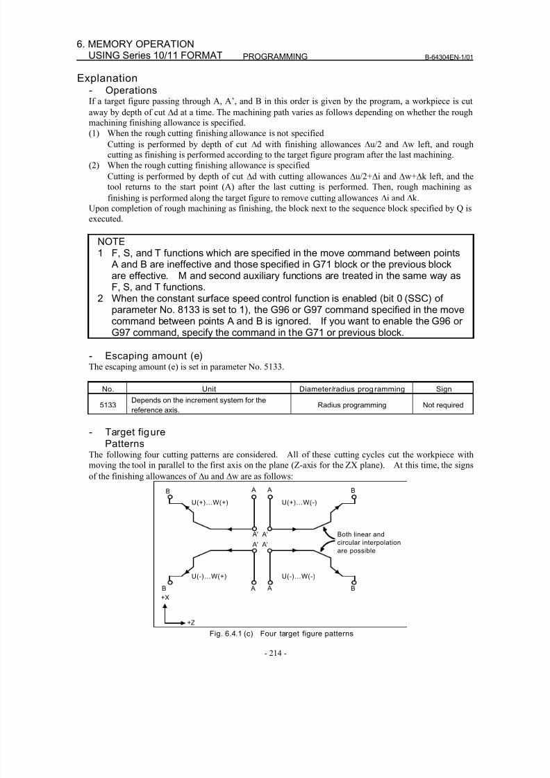
8/16/2019 Manual Operacion para FANUC
http://slidepdf.com/reader/full/manual-operacion-para-fanuc 232/435
PROGRAMMING B-64304EN-1/01
- 214 -
6. MEMORY OPERATIONUSING Series 10/11 FORMAT
Explanation- OperationsIf a target figure passing through A, A’, and B in this order is given by the program, a workpiece is cut
away by depth of cut Δd at a time. The machining path varies as follows depending on whether the rough
machining finishing allowance is specified.(1) When the rough cutting finishing allowance is not specified
Cutting is performed by depth of cut Δd with finishing allowances Δu/2 and Δw left, and rough
cutting as finishing is performed according to the target figure program after the last machining.
(2) When the rough cutting finishing allowance is specified
Cutting is performed by depth of cut Δd with cutting allowances Δu/2+Δi and Δw+Δk left, and the
tool returns to the start point (A) after the last cutting is performed. Then, rough machining as
finishing is performed along the target figure to remove cutting allowances Δi and Δk.
Upon completion of rough machining as finishing, the block next to the sequence block specified by Q is
executed.
NOTE1 F, S, and T functions which are specified in the move command between points
A and B are ineffective and those specified in G71 block or the previous blockare effective. M and second auxiliary functions are treated in the same way asF, S, and T functions.
2 When the constant surface speed control function is enabled (bit 0 (SSC) ofparameter No. 8133 is set to 1), the G96 or G97 command specified in the movecommand between points A and B is ignored. If you want to enable the G96 orG97 command, specify the command in the G71 or previous block.
- Escaping amount (e)
The escaping amount (e) is set in parameter No. 5133.
No. Unit Diameter/radius programming Sign
5133Depends on the increment system for the
reference axis.Radius programming Not required
- Target figurePatterns
The following four cutting patterns are considered. All of these cutting cycles cut the workpiece with
moving the tool in parallel to the first axis on the plane (Z-axis for the ZX plane). At this time, the signs
of the finishing allowances of Δu and Δw are as follows:
Both linear and
circular interpolation
are possible
A'
B
U(+)…W(+)
A'
B A
U(+)…W(-)
A'
B A
U(-)…W(+)
A'
B A
U(-)…W(-)
A
+X
+Z
Fig. 6.4.1 (c) Four target figure patterns
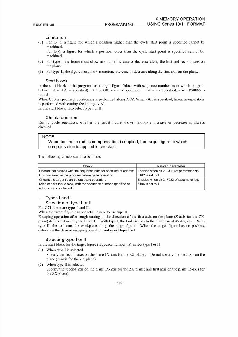
8/16/2019 Manual Operacion para FANUC
http://slidepdf.com/reader/full/manual-operacion-para-fanuc 233/435
B-64304EN-1/01 PROGRAMMING
- 215 -
6.MEMORY OPERATIONUSING Series 10/11 FORMAT
Limitation(1) For U(+), a figure for which a position higher than the cycle start point is specified cannot be
machined.
For U(-), a figure for which a position lower than the cycle start point is specified cannot bemachined.
(2) For type I, the figure must show monotone increase or decrease along the first and second axes on
the plane.
(3) For type II, the figure must show monotone increase or decrease along the first axis on the plane.
Start blockIn the start block in the program for a target figure (block with sequence number ns in which the path
between A and A' is specified), G00 or G01 must be specified. If it is not specified, alarm PS0065 is
issued.
When G00 is specified, positioning is performed along A-A'. When G01 is specified, linear interpolation
is performed with cutting feed along A-A'.
In this start block, also select type I or II.
Check functionsDuring cycle operation, whether the target figure shows monotone increase or decrease is always
checked.
NOTEWhen tool nose radius compensation is applied, the target figure to whichcompensation is applied is checked.
The following checks can also be made.
Check Related parameter
Checks that a block with the sequence number specified at address
Q is contained in the program before cycle operation.
Enabled when bit 2 (QSR) of parameter No.
5102 is set to 1.
Checks the target figure before cycle operation.
(Also checks that a block with the sequence number specified at
address Q is contained.)
Enabled when bit 2 (FCK) of parameter No.
5104 is set to 1.
- Types I and IISelection of type I or II
For G71, there are types I and II.
When the target figure has pockets, be sure to use type II.Escaping operation after rough cutting in the direction of the first axis on the plane (Z-axis for the ZX
plane) differs between types I and II. With type I, the tool escapes to the direction of 45 degrees. With
type II, the tool cuts the workpiece along the target figure. When the target figure has no pockets,
determine the desired escaping operation and select type I or II.
Selecting type I or IIIn the start block for the target figure (sequence number ns), select type I or II.
(1) When type I is selected
Specify the second axis on the plane (X-axis for the ZX plane). Do not specify the first axis on the
plane (Z-axis for the ZX plane).
(2) When type II is selectedSpecify the second axis on the plane (X-axis for the ZX plane) and first axis on the plane (Z-axis for
the ZX plane).
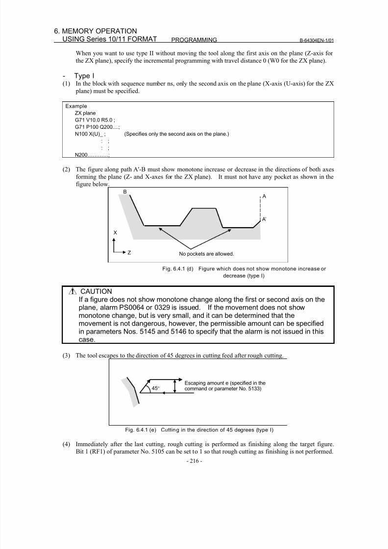
8/16/2019 Manual Operacion para FANUC
http://slidepdf.com/reader/full/manual-operacion-para-fanuc 234/435
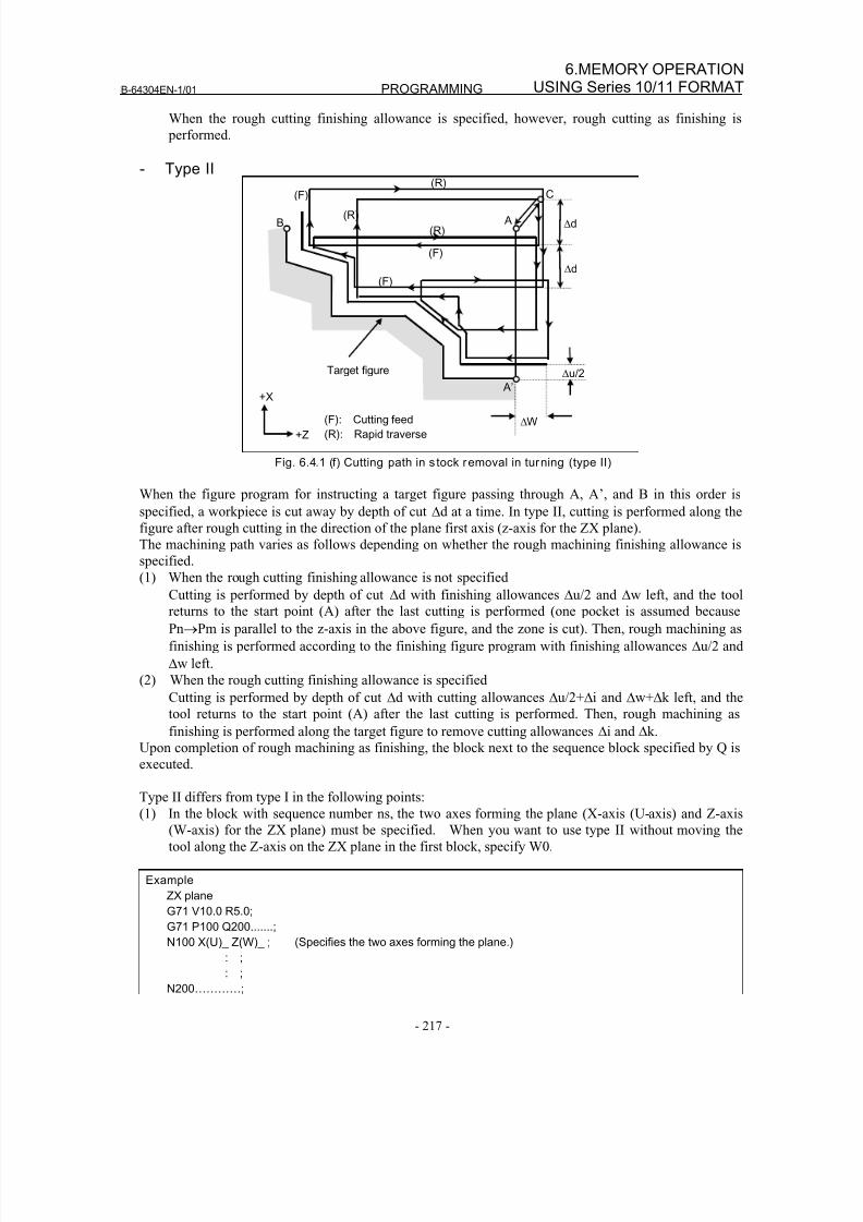
8/16/2019 Manual Operacion para FANUC
http://slidepdf.com/reader/full/manual-operacion-para-fanuc 235/435
B-64304EN-1/01 PROGRAMMING
- 217 -
6.MEMORY OPERATIONUSING Series 10/11 FORMAT
When the rough cutting finishing allowance is specified, however, rough cutting as finishing is
performed.
- Type II
C
B
(F)
A
Δu/2
Δd
A’
ΔW
Target figure
(F): Cutting feed
(R): Rapid traverse
+X
+Z
(R)
Δd
(F)
(F)
(R)
(R)
Fig. 6.4.1 (f) Cutting path in s tock removal in turning (type II)
When the figure program for instructing a target figure passing through A, A’, and B in this order is
specified, a workpiece is cut away by depth of cut Δd at a time. In type II, cutting is performed along the
figure after rough cutting in the direction of the plane first axis (z-axis for the ZX plane).
The machining path varies as follows depending on whether the rough machining finishing allowance is
specified.
(1) When the rough cutting finishing allowance is not specifiedCutting is performed by depth of cut Δd with finishing allowances Δu/2 and Δw left, and the tool
returns to the start point (A) after the last cutting is performed (one pocket is assumed because
Pn→Pm is parallel to the z-axis in the above figure, and the zone is cut). Then, rough machining as
finishing is performed according to the finishing figure program with finishing allowances Δu/2 and
Δw left.
(2) When the rough cutting finishing allowance is specified
Cutting is performed by depth of cut Δd with cutting allowances Δu/2+Δi and Δw+Δk left, and the
tool returns to the start point (A) after the last cutting is performed. Then, rough machining as
finishing is performed along the target figure to remove cutting allowances Δi and Δk.
Upon completion of rough machining as finishing, the block next to the sequence block specified by Q is
executed.
Type II differs from type I in the following points:
(1) In the block with sequence number ns, the two axes forming the plane (X-axis (U-axis) and Z-axis
(W-axis) for the ZX plane) must be specified. When you want to use type II without moving the
tool along the Z-axis on the ZX plane in the first block, specify W0.
Example
ZX plane
G71 V10.0 R5.0;
G71 P100 Q200.......;
N100 X(U)_ Z(W)_ ; (Specifies the two axes forming the plane.)
: ;: ;
N200…………;
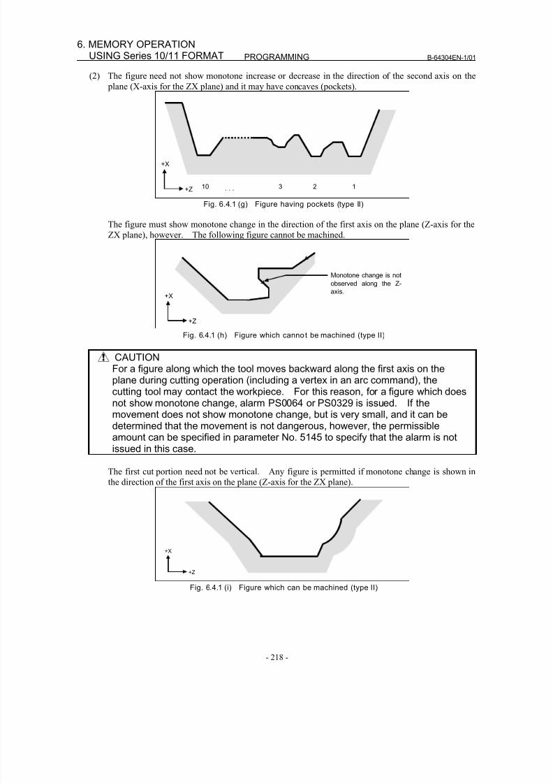
8/16/2019 Manual Operacion para FANUC
http://slidepdf.com/reader/full/manual-operacion-para-fanuc 236/435
PROGRAMMING B-64304EN-1/01
- 218 -
6. MEMORY OPERATIONUSING Series 10/11 FORMAT
(2) The figure need not show monotone increase or decrease in the direction of the second axis on the
plane (X-axis for the ZX plane) and it may have concaves (pockets).
12310 . . .
+X
+Z
Fig. 6.4.1 (g) Figure having pockets (type II)
The figure must show monotone change in the direction of the first axis on the plane (Z-axis for the
ZX plane), however. The following figure cannot be machined.
Monotone change is not
observed along the Z-
axis.+X
+Z
Fig. 6.4.1 (h) Figure which cannot be machined (type II)
CAUTION
For a figure along which the tool moves backward along the first axis on theplane during cutting operation (including a vertex in an arc command), thecutting tool may contact the workpiece. For this reason, for a figure which doesnot show monotone change, alarm PS0064 or PS0329 is issued. If themovement does not show monotone change, but is very small, and it can bedetermined that the movement is not dangerous, however, the permissibleamount can be specified in parameter No. 5145 to specify that the alarm is notissued in this case.
The first cut portion need not be vertical. Any figure is permitted if monotone change is shown in
the direction of the first axis on the plane (Z-axis for the ZX plane).
+X
+Z
Fig. 6.4.1 (i) Figure which can be machined (type II)
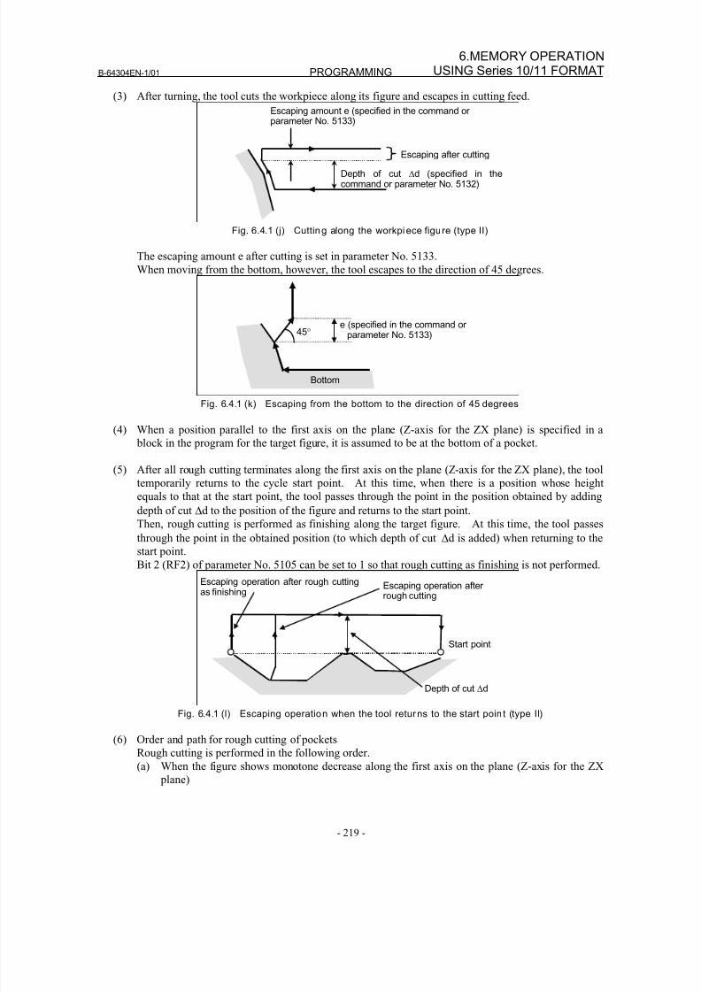
8/16/2019 Manual Operacion para FANUC
http://slidepdf.com/reader/full/manual-operacion-para-fanuc 237/435
B-64304EN-1/01 PROGRAMMING
- 219 -
6.MEMORY OPERATIONUSING Series 10/11 FORMAT
(3) After turning, the tool cuts the workpiece along its figure and escapes in cutting feed.
Escaping amount e (specified in the command or parameter No. 5133)
Depth of cut Δd (specified in thecommand or parameter No. 5132)
Escaping after cutting
Fig. 6.4.1 (j) Cutting along the workpiece figure (type II)
The escaping amount e after cutting is set in parameter No. 5133.
When moving from the bottom, however, the tool escapes to the direction of 45 degrees.
e (specified in the command or parameter No. 5133)45°
Bottom
Fig. 6.4.1 (k) Escaping from the bottom to the direction of 45 degrees
(4) When a position parallel to the first axis on the plane (Z-axis for the ZX plane) is specified in a
block in the program for the target figure, it is assumed to be at the bottom of a pocket.
(5) After all rough cutting terminates along the first axis on the plane (Z-axis for the ZX plane), the tooltemporarily returns to the cycle start point. At this time, when there is a position whose height
equals to that at the start point, the tool passes through the point in the position obtained by adding
depth of cut Δd to the position of the figure and returns to the start point.
Then, rough cutting is performed as finishing along the target figure. At this time, the tool passes
through the point in the obtained position (to which depth of cut Δd is added) when returning to the
start point.
Bit 2 (RF2) of parameter No. 5105 can be set to 1 so that rough cutting as finishing is not performed.
Depth of cut Δd
Start point
Escaping operation after rough cutting
Escaping operation after rough cuttingas finishing
Fig. 6.4.1 (l) Escaping operation when the tool returns to the start point (type II)
(6) Order and path for rough cutting of pockets
Rough cutting is performed in the following order.
(a) When the figure shows monotone decrease along the first axis on the plane (Z-axis for the ZX
plane)
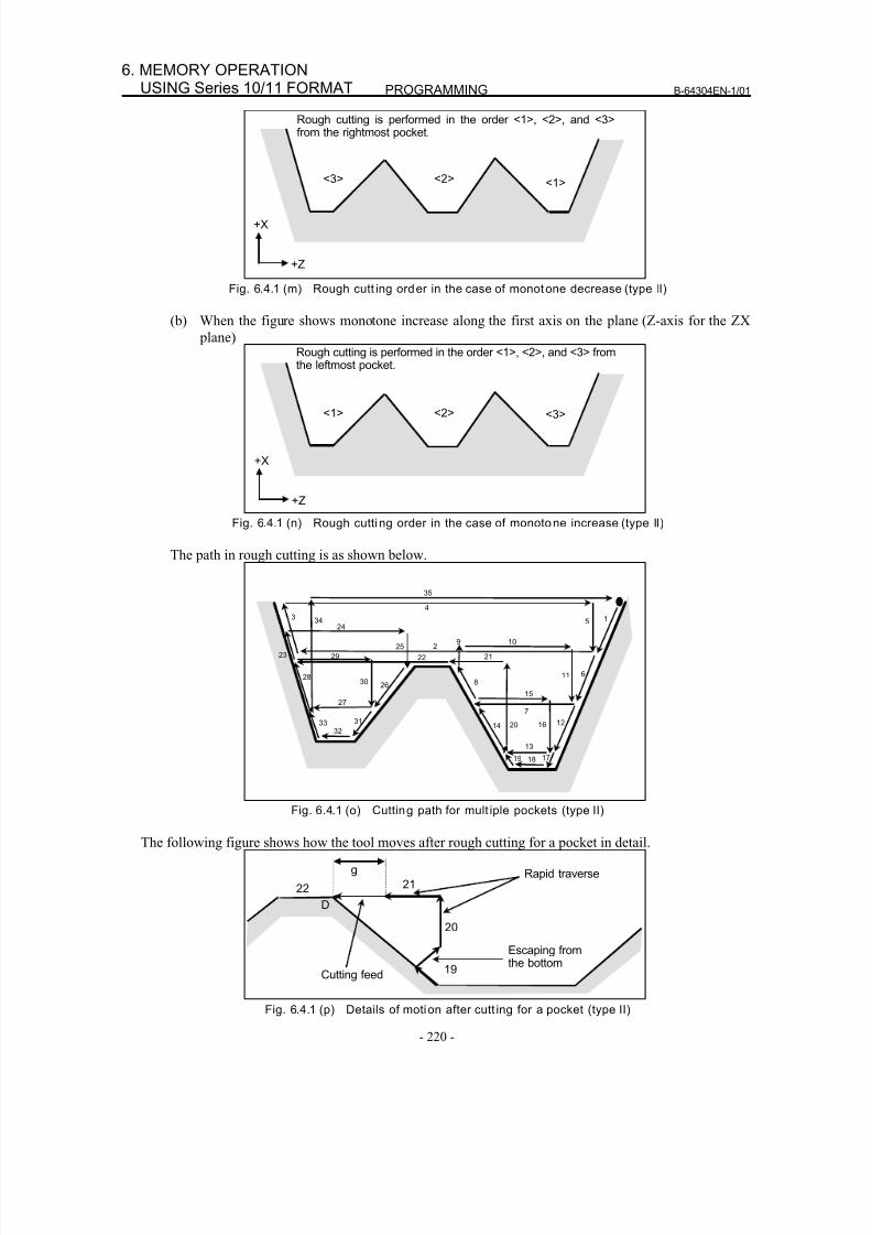
8/16/2019 Manual Operacion para FANUC
http://slidepdf.com/reader/full/manual-operacion-para-fanuc 238/435
PROGRAMMING B-64304EN-1/01
- 220 -
6. MEMORY OPERATIONUSING Series 10/11 FORMAT
<1><2><3>
Rough cutting is performed in the order <1>, <2>, and <3>from the rightmost pocket.
+X
+Z
Fig. 6.4.1 (m) Rough cutt ing order in the case of monotone decrease (type II)
(b) When the figure shows monotone increase along the first axis on the plane (Z-axis for the ZX
plane)
<3><2><1>
Rough cutting is performed in the order <1>, <2>, and <3> fromthe leftmost pocket.
+X
+Z
Fig. 6.4.1 (n) Rough cutting order in the case of monotone increase (type II)
The path in rough cutting is as shown below.
18
23
2830
27
26
24
25
22
9 102
14 20
7
13
19
5 1
611
1216
17
8
4
21
15
29
3
31
3233
34
35
Fig. 6.4.1 (o) Cutting path for mult iple pockets (type II)
The following figure shows how the tool moves after rough cutting for a pocket in detail.
19
20
22 21•
g Rapid traverse
Escaping fromthe bottom
Cutting feed
D
Fig. 6.4.1 (p) Details of motion after cutt ing for a pocket (type II)
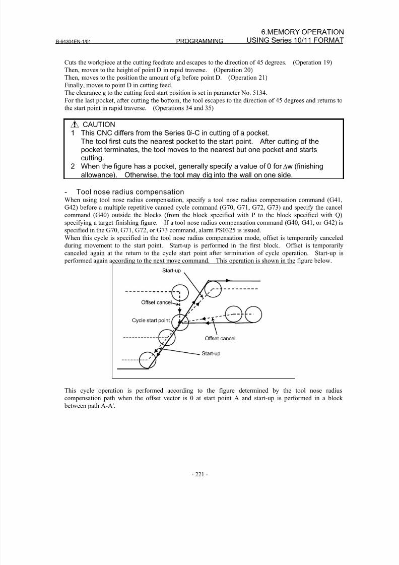
8/16/2019 Manual Operacion para FANUC
http://slidepdf.com/reader/full/manual-operacion-para-fanuc 239/435
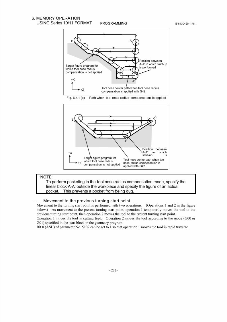
8/16/2019 Manual Operacion para FANUC
http://slidepdf.com/reader/full/manual-operacion-para-fanuc 240/435
PROGRAMMING B-64304EN-1/01
- 222 -
6. MEMORY OPERATIONUSING Series 10/11 FORMAT
Target figure program forwhich tool nose radiuscompensation is not applied
+X
+Z
B A
A’
Tool nose center path when tool nose radiuscompensation is applied with G42
Position between A-A' in which start-upis performed
Fig. 6.4.1 (q) Path when tool nose radius compensation is applied
Target figure program forwhich tool nose radiuscompensation is not applied
+X
+Z Tool nose center path when toolnose radius compensation isapplied with G42
B A
A’
Position between
A-A' in whichstart-up is
NOTETo perform pocketing in the tool nose radius compensation mode, specify thelinear block A-A' outside the workpiece and specify the figure of an actualpocket. This prevents a pocket from being dug.
- Movement to the previous turning start pointMovement to the turning start point is performed with two operations. (Operations 1 and 2 in the figure
below.) As movement to the present turning start point, operation 1 temporarily moves the tool to the
previous turning start point, then operation 2 moves the tool to the present turning start point.
Operation 1 moves the tool in cutting feed. Operation 2 moves the tool according to the mode (G00 or
G01) specified in the start block in the geometry program.
Bit 0 (ASU) of parameter No. 5107 can be set to 1 so that operation 1 moves the tool in rapid traverse.
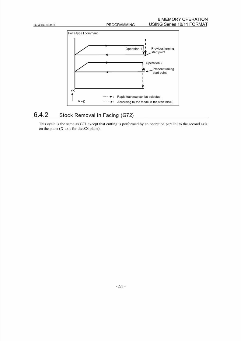
8/16/2019 Manual Operacion para FANUC
http://slidepdf.com/reader/full/manual-operacion-para-fanuc 241/435
B-64304EN-1/01 PROGRAMMING
- 223 -
6.MEMORY OPERATIONUSING Series 10/11 FORMAT
For a type I command
+X
+Z
: Rapid traverse can be selected.
: According to the mode in the start block.
Operation 1
Operation 2
Previous turning
start point
Present turningstart point
6.4.2 Stock Removal in Facing (G72)
This cycle is the same as G71 except that cutting is performed by an operation parallel to the second axis
on the plane (X-axis for the ZX plane).
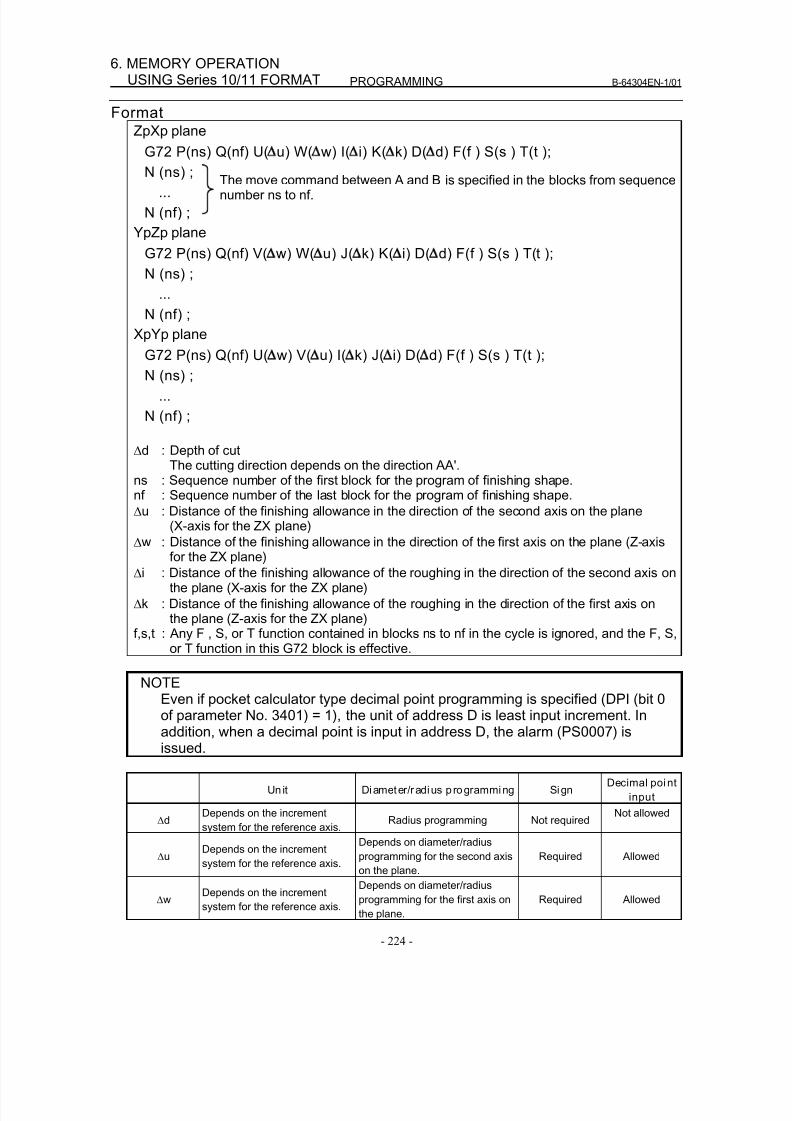
8/16/2019 Manual Operacion para FANUC
http://slidepdf.com/reader/full/manual-operacion-para-fanuc 242/435
PROGRAMMING B-64304EN-1/01
- 224 -
6. MEMORY OPERATIONUSING Series 10/11 FORMAT
FormatZpXp plane
G72 P(ns) Q(nf) U( u) W( w) I( i) K( k) D( d) F(f ) S(s ) T(t );
N (ns) ;...
N (nf) ;
YpZp plane
G72 P(ns) Q(nf) V( w) W( u) J( k) K( i) D( d) F(f ) S(s ) T(t );
N (ns) ;
...
N (nf) ;
XpYp plane
G72 P(ns) Q(nf) U( w) V( u) I( k) J( i) D( d) F(f ) S(s ) T(t );
N (ns) ;
...
N (nf) ;
Δd : Depth of cutThe cutting direction depends on the direction AA'.
ns : Sequence number of the first block for the program of finishing shape.nf : Sequence number of the last block for the program of finishing shape.
Δu : Distance of the finishing allowance in the direction of the second axis on the plane
(X-axis for the ZX plane)Δw : Distance of the finishing allowance in the direction of the first axis on the plane (Z-axis
for the ZX plane)
Δi : Distance of the finishing allowance of the roughing in the direction of the second axis onthe plane (X-axis for the ZX plane)
Δk : Distance of the finishing allowance of the roughing in the direction of the first axis onthe plane (Z-axis for the ZX plane)
f,s,t : Any F , S, or T function contained in blocks ns to nf in the cycle is ignored, and the F, S,or T function in this G72 block is effective.
NOTE
Even if pocket calculator type decimal point programming is specified (DPI (bit 0of parameter No. 3401) = 1), the unit of address D is least input increment. Inaddition, when a decimal point is input in address D, the alarm (PS0007) isissued.
Unit Diameter/radius p rogramming SignDecimal point
input
ΔdDepends on the increment
system for the reference axis.Radius programming Not required
Not allowed
ΔuDepends on the increment
system for the reference axis.
Depends on diameter/radius
programming for the second axis
on the plane.
Required Allowed
ΔwDepends on the increment
system for the reference axis.
Depends on diameter/radius
programming for the first axis on
the plane.
Required Allowed
The move command between A and B is specified in the blocks from sequencenumber ns to nf.
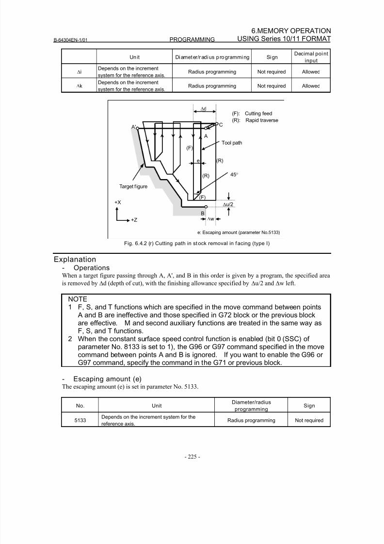
8/16/2019 Manual Operacion para FANUC
http://slidepdf.com/reader/full/manual-operacion-para-fanuc 243/435
B-64304EN-1/01 PROGRAMMING
- 225 -
6.MEMORY OPERATIONUSING Series 10/11 FORMAT
Un it Diameter/radius p rogramming SignDecimal point
input
ΔiDepends on the increment
system for the reference axis.Radius programming Not required Allowed
ΔkDepends on the increment
system for the reference axis. Radius programming Not required Allowed
A'
Δu/2
Δd
B
Tool path (F)
(R)
e
45°
(R)
(F)
A
C
Δw
Target f igure
(F): Cutting feed
(R): Rapid traverse
+X
+Z
e: Escaping amount (parameter No.5133)
Fig. 6.4.2 (r) Cutting path in stock removal in facing (type I)
Explanation- OperationsWhen a target figure passing through A, A', and B in this order is given by a program, the specified area
is removed by Δd (depth of cut), with the finishing allowance specified by Δu/2 and Δw left.
NOTE1 F, S, and T functions which are specified in the move command between points
A and B are ineffective and those specified in G72 block or the previous blockare effective. M and second auxiliary functions are treated in the same way asF, S, and T functions.
2 When the constant surface speed control function is enabled (bit 0 (SSC) ofparameter No. 8133 is set to 1), the G96 or G97 command specified in the movecommand between points A and B is ignored. If you want to enable the G96 orG97 command, specify the command in the G71 or previous block.
- Escaping amount (e)The escaping amount (e) is set in parameter No. 5133.
No. UnitDiameter/radius
programmingSign
5133Depends on the increment system for the
reference axis.Radius programming Not required
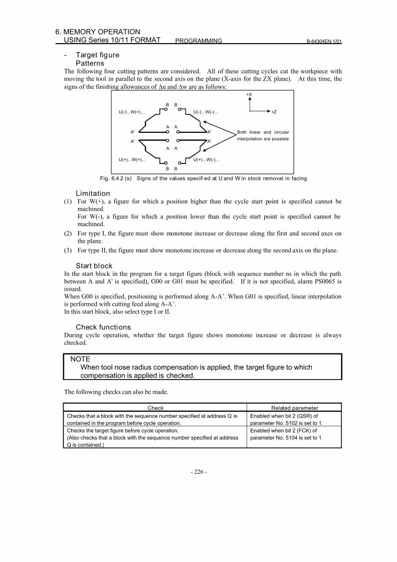
8/16/2019 Manual Operacion para FANUC
http://slidepdf.com/reader/full/manual-operacion-para-fanuc 244/435
PROGRAMMING B-64304EN-1/01
- 226 -
6. MEMORY OPERATIONUSING Series 10/11 FORMAT
- Target figurePatterns
The following four cutting patterns are considered. All of these cutting cycles cut the workpiece with
moving the tool in parallel to the second axis on the plane (X-axis for the ZX plane). At this time, the
signs of the finishing allowances of Δu and Δw are as follows:
Both linear and circular
interpolation are possible
+X
+Z
B
A
U(-)...W(+)...
A'
B
A
U(-)...W(-)...
A'
B
A
U(+)...W(+)...
A'
B
A
U(+)...W(-)...
A'
Fig. 6.4.2 (s) Signs of the values specified at U and W in stock removal in facing
Limitation(1) For W(+), a figure for which a position higher than the cycle start point is specified cannot be
machined.
For W(-), a figure for which a position lower than the cycle start point is specified cannot be
machined.
(2) For type I, the figure must show monotone increase or decrease along the first and second axes on
the plane.
(3) For type II, the figure must show monotone increase or decrease along the second axis on the plane.
Start blockIn the start block in the program for a target figure (block with sequence number ns in which the path
between A and A' is specified), G00 or G01 must be specified. If it is not specified, alarm PS0065 is
issued.
When G00 is specified, positioning is performed along A-A’. When G01 is specified, linear interpolation
is performed with cutting feed along A-A’.
In this start block, also select type I or II.
Check functionsDuring cycle operation, whether the target figure shows monotone increase or decrease is always
checked.
NOTEWhen tool nose radius compensation is applied, the target figure to whichcompensation is applied is checked.
The following checks can also be made.
Check Related parameter
Checks that a block with the sequence number specified at address Q is
contained in the program before cycle operation.
Enabled when bit 2 (QSR) of
parameter No. 5102 is set to 1.
Checks the target figure before cycle operation.
(Also checks that a block with the sequence number specified at address
Q is contained.)
Enabled when bit 2 (FCK) of
parameter No. 5104 is set to 1.
8/16/2019 Manual Operacion para FANUC
http://slidepdf.com/reader/full/manual-operacion-para-fanuc 245/435
B-64304EN-1/01 PROGRAMMING
- 227 -
6.MEMORY OPERATIONUSING Series 10/11 FORMAT
- Types I and IISelection of type I or II
For G72, there are types I and II.
When the target figure has pockets, be sure to use type II.
Escaping operation after rough cutting in the direction of the second axis on the plane (X-axis for the ZX plane) differs between types I and II. With type I, the tool escapes to the direction of 45 degrees. With
type II, the tool cuts the workpiece along the target figure. When the target figure has no pockets,
determine the desired escaping operation and select type I or II.
Selecting type I or IIIn the start block for the target figure (sequence number ns), select type I or II.
(1) When type I is selected
Specify the first axis on the plane (Z-axis for the ZX plane). Do not specify the second axis on the
plane (X-axis for the ZX plane).
(2) When type II is selected
Specify the second axis on the plane (X-axis for the ZX plane) and first axis on the plane (Z-axis forthe ZX plane).
When you want to use type II without moving the tool along the second axis on the plane (X-axis for
the ZX plane), specify the incremental programming with travel distance 0 (U0 for the ZX plane).
- Type IG72 differs from G71 in the following points:
(1) G72 cuts the workpiece with moving the tool in parallel with the second axis on the plane (X-axis on
the ZX plane).
(2) In the start block in the program for a target figure (block with sequence number ns), only the first
axis on the plane (Z-axis (W-axis) for the ZX plane) must be specified.
- Type IIG72 differs from G71 in the following points:
(1) G72 cuts the workpiece with moving the tool in parallel with the second axis on the plane (X-axis on
the ZX plane).
(2) The figure need not show monotone increase or decrease in the direction of the first axis on the
plane (Z-axis for the ZX plane) and it may have concaves (pockets). The figure must show
monotone change in the direction of the second axis on the plane (X-axis for the ZX plane),
however.
(3) When a position parallel to the second axis on the plane (X-axis for the ZX plane) is specified in a
block in the program for the target figure, it is assumed to be at the bottom of a pocket.
(4) After all rough cutting terminates along the second axis on the plane (X-axis for the ZX plane), thetool temporarily returns to the start point. Then, rough cutting as finishing is performed.
- Tool nose radius compensationSee the pages on which G71 is explained.
- Movement to the previous turning start pointSee the pages on which G71 is explained.
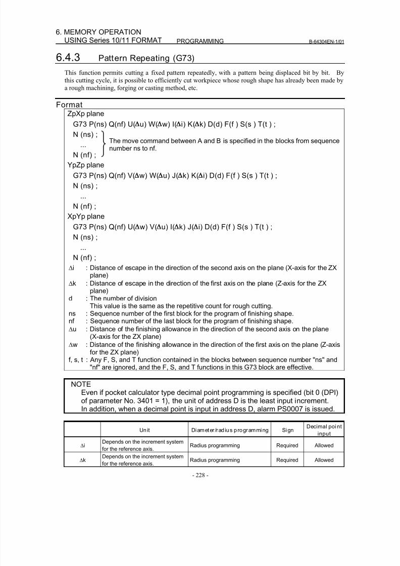
8/16/2019 Manual Operacion para FANUC
http://slidepdf.com/reader/full/manual-operacion-para-fanuc 246/435
PROGRAMMING B-64304EN-1/01
- 228 -
6. MEMORY OPERATIONUSING Series 10/11 FORMAT
6.4.3 Pattern Repeating (G73)
This function permits cutting a fixed pattern repeatedly, with a pattern being displaced bit by bit. By
this cutting cycle, it is possible to efficiently cut workpiece whose rough shape has already been made by
a rough machining, forging or casting method, etc.
FormatZpXp plane
G73 P(ns) Q(nf) U( u) W( w) I( i) K( k) D(d) F(f ) S(s ) T(t ) ;
N (ns) ;
...
N (nf) ;
YpZp plane
G73 P(ns) Q(nf) V( w) W( u) J( k) K( i) D(d) F(f ) S(s ) T(t ) ;N (ns) ;
...
N (nf) ;
XpYp plane
G73 P(ns) Q(nf) U( w) V( u) I( k) J( i) D(d) F(f ) S(s ) T(t ) ;
N (ns) ;
...
N (nf) ;
Δi : Distance of escape in the direction of the second axis on the plane (X-axis for the ZXplane)
Δk : Distance of escape in the direction of the first axis on the plane (Z-axis for the ZXplane)
d : The number of divisionThis value is the same as the repetitive count for rough cutting.
ns : Sequence number of the first block for the program of finishing shape.nf : Sequence number of the last block for the program of finishing shape.
Δu : Distance of the finishing allowance in the direction of the second axis on the plane(X-axis for the ZX plane)
Δw : Distance of the finishing allowance in the direction of the first axis on the plane (Z-axis
for the ZX plane)f, s, t : Any F, S, and T function contained in the blocks between sequence number "ns" and"nf" are ignored, and the F, S, and T functions in this G73 block are effective.
NOTEEven if pocket calculator type decimal point programming is specified (bit 0 (DPI)of parameter No. 3401 = 1), the unit of address D is the least input increment.In addition, when a decimal point is input in address D, alarm PS0007 is issued.
Unit Diameter /rad ius programming SignDecimal point
input
Δi Depends on the increment systemfor the reference axis. Radius programming Required Allowed
ΔkDepends on the increment system
for the reference axis.Radius programming Required Allowed
The move command between A and B is specified in the blocks from sequencenumber ns to nf.
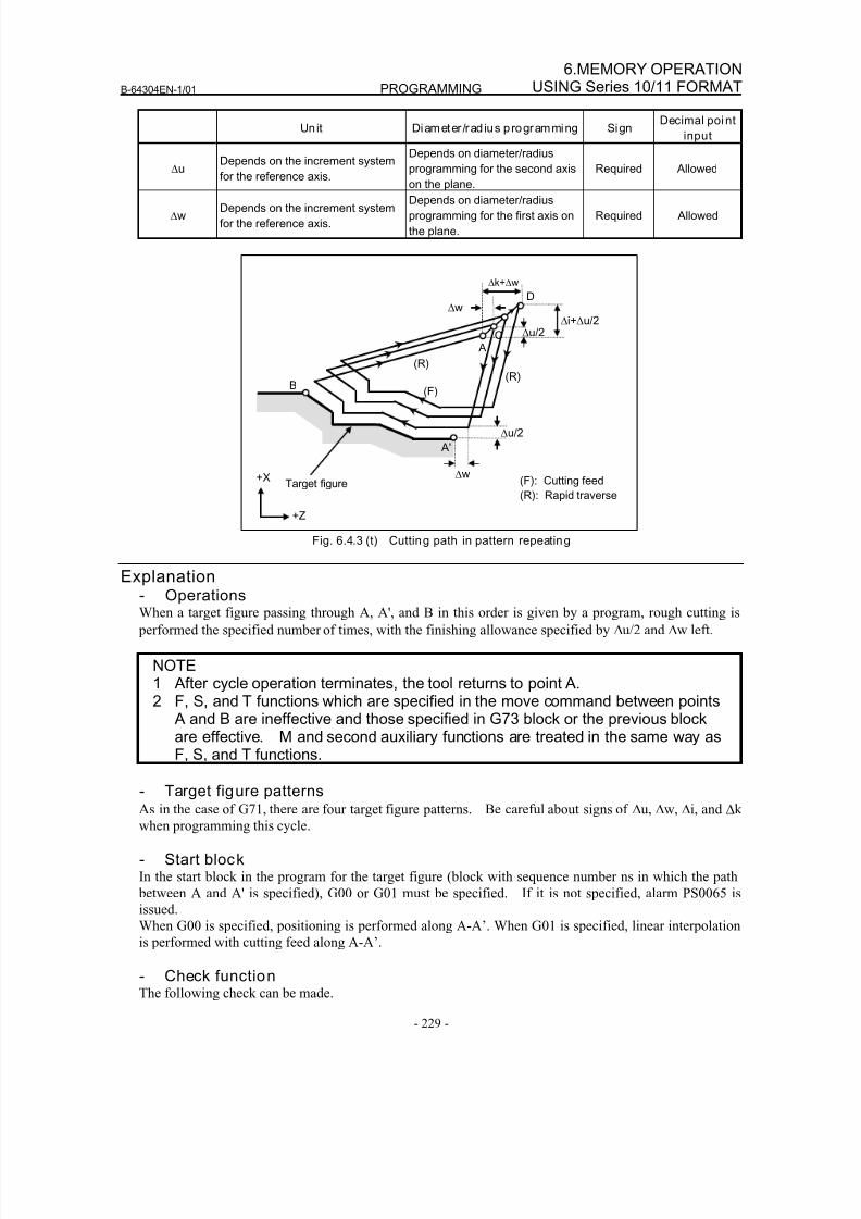
8/16/2019 Manual Operacion para FANUC
http://slidepdf.com/reader/full/manual-operacion-para-fanuc 247/435
B-64304EN-1/01 PROGRAMMING
- 229 -
6.MEMORY OPERATIONUSING Series 10/11 FORMAT
Unit Diameter /rad ius programming SignDecimal point
input
ΔuDepends on the increment system
for the reference axis.
Depends on diameter/radius
programming for the second axis
on the plane.
Required Allowed
ΔwDepends on the increment system
for the reference axis.
Depends on diameter/radius
programming for the first axis on
the plane.
Required Allowed
Δw
A'
Δu/2 Δi+Δu/2
B
D
Δk+Δw
C
Δw
Δu/2
Target figure (F): Cutting feed
(R): Rapid traverse
(R)
+X
+Z
(R)
A
(F)
Fig. 6.4.3 (t) Cutting path in pattern repeating
Explanation- OperationsWhen a target figure passing through A, A', and B in this order is given by a program, rough cutting is
performed the specified number of times, with the finishing allowance specified by Δu/2 and Δw left.
NOTE1 After cycle operation terminates, the tool returns to point A.2 F, S, and T functions which are specified in the move command between points
A and B are ineffective and those specified in G73 block or the previous blockare effective. M and second auxiliary functions are treated in the same way asF, S, and T functions.
- Target figure patternsAs in the case of G71, there are four target figure patterns. Be careful about signs of Δu, Δw, Δi, and Δk
when programming this cycle.
- Start blockIn the start block in the program for the target figure (block with sequence number ns in which the path
between A and A' is specified), G00 or G01 must be specified. If it is not specified, alarm PS0065 is
issued.
When G00 is specified, positioning is performed along A-A’. When G01 is specified, linear interpolation
is performed with cutting feed along A-A’.
- Check functionThe following check can be made.
8/16/2019 Manual Operacion para FANUC
http://slidepdf.com/reader/full/manual-operacion-para-fanuc 248/435
PROGRAMMING B-64304EN-1/01
- 230 -
6. MEMORY OPERATIONUSING Series 10/11 FORMAT
Check Related parameter
Checks that a block with the sequence number specified at address
Q is contained in the program before cycle operation.
Enabled when bit 2 (QSR) of parameter
No. 5102 is set to 1.
- Tool nose radius compensationLike G71, this cycle operation is performed according to the figure determined by the tool nose radius
compensation path when the offset vector is 0 at start point A and start-up is performed in a block
between path A-A'.
6.4.4 Finishing Cycle (G70)
After rough cutting by G71, G72 or G73, the following command permits finishing.
Format
G70 P(ns) Q(nf) ;ns : Sequence number of the first block for the program of finishing shape.nf : Sequence number of the last block for the program of finishing shape.
Explanation- OperationsThe blocks with sequence numbers ns to nf in the program for a target figure are executed for finishing.
The F, S, T, M, and second auxiliary functions specified in the G71, G72, or G73 block are ignored and
the F, S, T, M, and second auxiliary functions specified in the blocks with sequence numbers ns to nf are
effective.
When cycle operation terminates, the tool is returned to the start point in rapid traverse and the next G70
cycle block is read.
- Target figure check functionThe following check can be made.
Check Related parameter
Checks that a block with the sequence number specified at address
Q is contained in the program before cycle operation.
Enabled when bit 2 (QSR) of parameter
No. 5102 is set to 1.
- Storing P and Q blocksWhen rough cutting is executed by G71, G72, or G73, up to three memory addresses of P and Q blocks
are stored. By this, the blocks indicated by P and Q are immediately found at execution of G70 withoutsearching memory from the beginning for them. After some G71, G72, and G73 rough cutting cycles
are executed, finishing cycles can be performed by G70 at a time. At this time, for the fourth and
subsequent rough cutting cycles, the cycle time is longer because memory is searched for P and Q blocks.
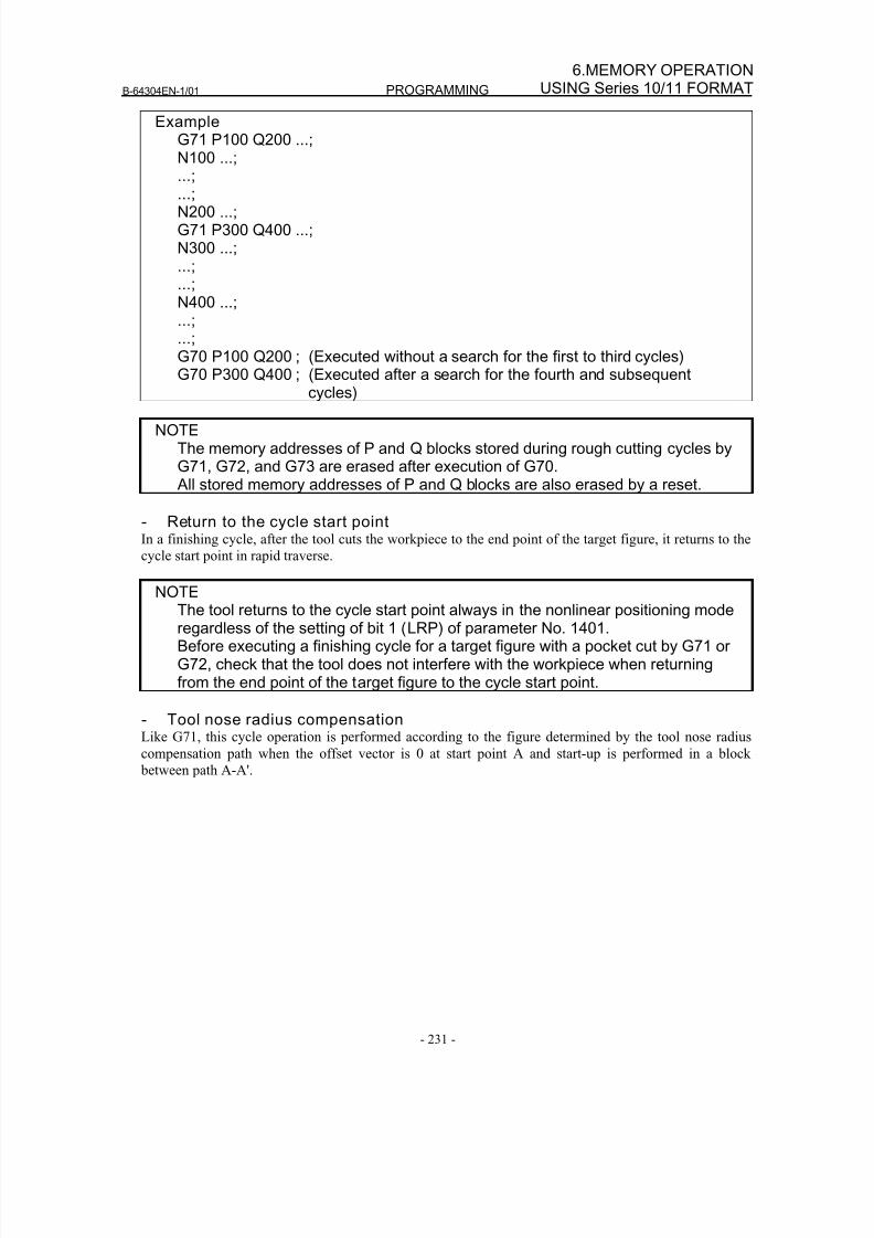
8/16/2019 Manual Operacion para FANUC
http://slidepdf.com/reader/full/manual-operacion-para-fanuc 249/435
B-64304EN-1/01 PROGRAMMING
- 231 -
6.MEMORY OPERATIONUSING Series 10/11 FORMAT
ExampleG71 P100 Q200 ...;N100 ...;...;
...;N200 ...;G71 P300 Q400 ...;N300 ...;...;...;N400 ...;...;...;G70 P100 Q200 ; (Executed without a search for the first to third cycles)G70 P300 Q400 ; (Executed after a search for the fourth and subsequent
cycles)
NOTEThe memory addresses of P and Q blocks stored during rough cutting cycles byG71, G72, and G73 are erased after execution of G70. All stored memory addresses of P and Q blocks are also erased by a reset.
- Return to the cycle start pointIn a finishing cycle, after the tool cuts the workpiece to the end point of the target figure, it returns to the
cycle start point in rapid traverse.
NOTEThe tool returns to the cycle start point always in the nonlinear positioning moderegardless of the setting of bit 1 (LRP) of parameter No. 1401.Before executing a finishing cycle for a target figure with a pocket cut by G71 orG72, check that the tool does not interfere with the workpiece when returningfrom the end point of the target figure to the cycle start point.
- Tool nose radius compensationLike G71, this cycle operation is performed according to the figure determined by the tool nose radius
compensation path when the offset vector is 0 at start point A and start-up is performed in a block
between path A-A'.
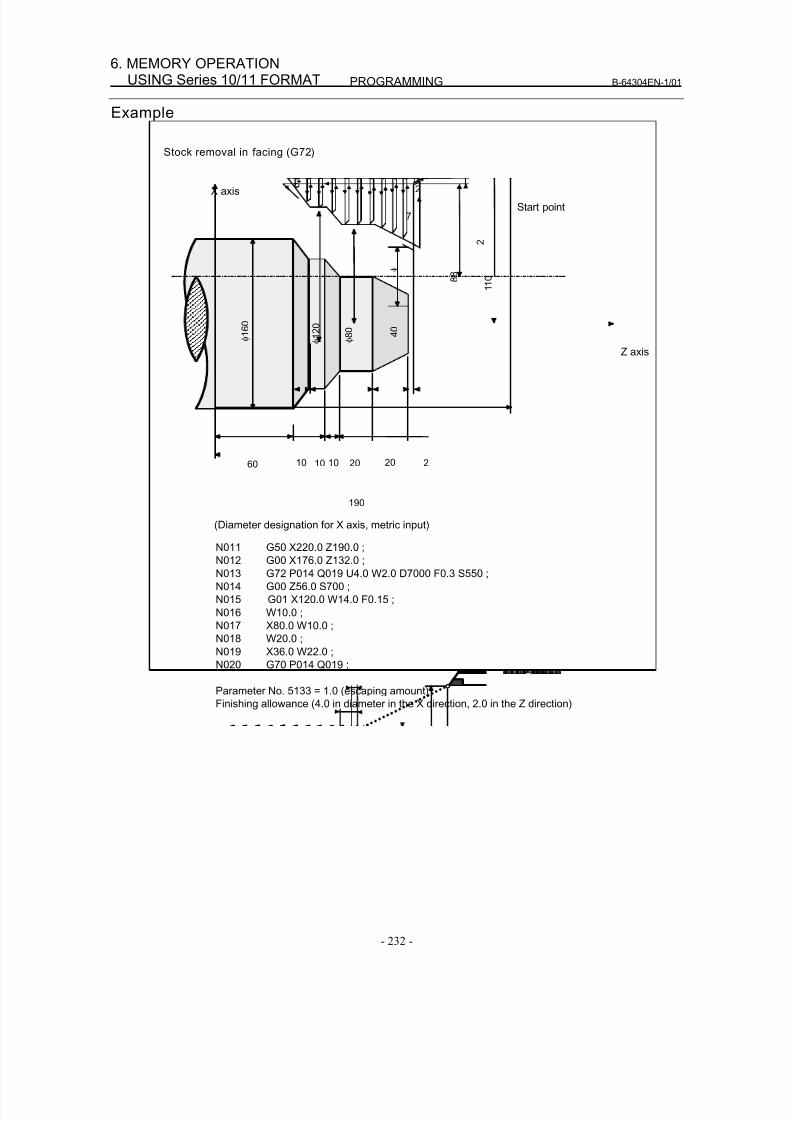
8/16/2019 Manual Operacion para FANUC
http://slidepdf.com/reader/full/manual-operacion-para-fanuc 250/435
PROGRAMMING B-64304EN-1/01
- 232 -
6. MEMORY OPERATIONUSING Series 10/11 FORMAT
Example
Stock removal in facing (G72)
(Diameter designation for X axis, metric input)
N011 G50 X220.0 Z190.0 ;
N012 G00 X176.0 Z132.0 ;
N013 G72 P014 Q019 U4.0 W2.0 D7000 F0.3 S550 ;
N014 G00 Z56.0 S700 ;
N015 G01 X120.0 W14.0 F0.15 ;
N016 W10.0 ;
N017 X80.0 W10.0 ;
N018 W20.0 ;
N019 X36.0 W22.0 ;
N020 G70 P014 Q019 ;
Parameter No. 5133 = 1.0 (escaping amount)
Finishing allowance (4.0 in diameter in the X direction, 2.0 in the Z direction)
φ 1 2 0
φ 8 0
4 0
φ 1 6 0
20 2
8 8
Start point
Z axis
X axis
201060 10 10
190
1 1 0
7
2
2
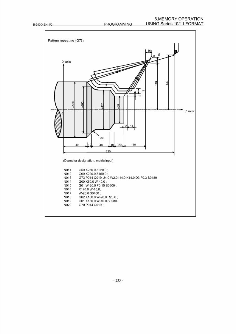
8/16/2019 Manual Operacion para FANUC
http://slidepdf.com/reader/full/manual-operacion-para-fanuc 251/435
B-64304EN-1/01 PROGRAMMING
- 233 -
6.MEMORY OPERATIONUSING Series 10/11 FORMAT
Pattern repeating (G73)
(Diameter designation, metric input)
φ 8 0
φ 1
8 0
Z axis
X axis
220
B
2
1 3 0
1 6
16
1 1 0
1 4
φ 1 6 0
2 14
0
20
φ 1 2
0
40 10 40 20 4010
N011 G50 X260.0 Z220.0 ;
N012 G00 X220.0 Z160.0 ;
N013 G73 P014 Q019 U4.0 W2.0 I14.0 K14.0 D3 F0.3 S0180
N014 G00 X80.0 W-40.0 ;
N015 G01 W-20.0 F0.15 S0600 ;
N016 X120.0 W-10.0;
N017 W-20.0 S0400 ;
N018 G02 X160.0 W-20.0 R20.0 ;
N019 G01 X180.0 W-10.0 S0280 ;
N020 G70 P014 Q019 ;
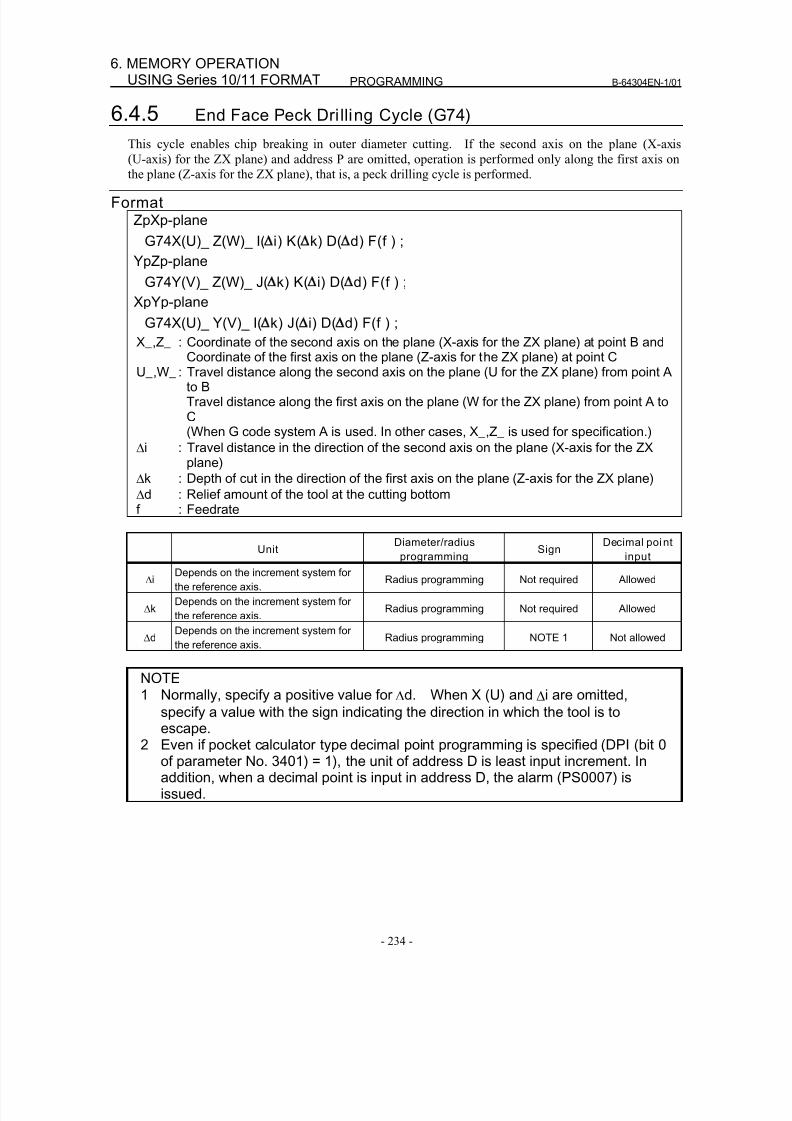
8/16/2019 Manual Operacion para FANUC
http://slidepdf.com/reader/full/manual-operacion-para-fanuc 252/435
PROGRAMMING B-64304EN-1/01
- 234 -
6. MEMORY OPERATIONUSING Series 10/11 FORMAT
6.4.5 End Face Peck Dri lling Cycle (G74)
This cycle enables chip breaking in outer diameter cutting. If the second axis on the plane (X-axis
(U-axis) for the ZX plane) and address P are omitted, operation is performed only along the first axis on
the plane (Z-axis for the ZX plane), that is, a peck drilling cycle is performed.
FormatZpXp-plane
G74X(U)_ Z(W)_ I( i) K( k) D( d) F(f ) ;
YpZp-plane
G74Y(V)_ Z(W)_ J( k) K( i) D( d) F(f ) ;
XpYp-plane
G74X(U)_ Y(V)_ I( k) J( i) D( d) F(f ) ;
X_,Z_ : Coordinate of the second axis on the plane (X-axis for the ZX plane) at point B andCoordinate of the first axis on the plane (Z-axis for the ZX plane) at point C
U_,W_ : Travel distance along the second axis on the plane (U for the ZX plane) from point Ato BTravel distance along the first axis on the plane (W for the ZX plane) from point A toC(When G code system A is used. In other cases, X_,Z_ is used for specification.)
Δi : Travel distance in the direction of the second axis on the plane (X-axis for the ZXplane)
Δk : Depth of cut in the direction of the first axis on the plane (Z-axis for the ZX plane)
Δd : Relief amount of the tool at the cutting bottomf : Feedrate
UnitDiameter/radius
programmingSign
Decimal point
input
ΔiDepends on the increment system for
the reference axis.Radius programming Not required Allowed
ΔkDepends on the increment system for
the reference axis.Radius programming Not required Allowed
ΔdDepends on the increment system for
the reference axis.Radius programming NOTE 1 Not allowed
NOTE1 Normally, specify a positive value for Δd. When X (U) and Δi are omitted,
specify a value with the sign indicating the direction in which the tool is toescape.
2 Even if pocket calculator type decimal point programming is specified (DPI (bit 0of parameter No. 3401) = 1), the unit of address D is least input increment. Inaddition, when a decimal point is input in address D, the alarm (PS0007) isissued.
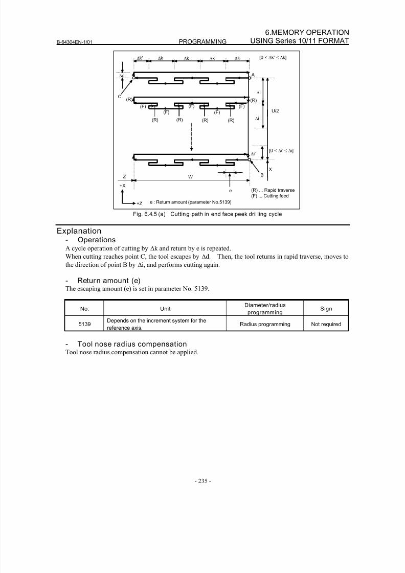
8/16/2019 Manual Operacion para FANUC
http://slidepdf.com/reader/full/manual-operacion-para-fanuc 253/435
B-64304EN-1/01 PROGRAMMING
- 235 -
6.MEMORY OPERATIONUSING Series 10/11 FORMAT
U/2
W
Δd
Δi’
C
Δk' Δk Δk Δk Δk
A
(R)
(R)
(F)
(R)(R)(R)
(F)
(F)
(F)
(F)
Δi
Δi
e
B
[0 < Δk’ ≤ Δk]
X
Z
(R)
[0 < Δi’ ≤ Δi]
(R) ... Rapid traverse
(F) ... Cutting feed
+X
+Z e : Return amount (parameter No.5139)
Fig. 6.4.5 (a) Cutting path in end face peek dril ling cycle
Explanation- OperationsA cycle operation of cutting by Δk and return by e is repeated.
When cutting reaches point C, the tool escapes by Δd. Then, the tool returns in rapid traverse, moves to
the direction of point B by Δi, and performs cutting again.
- Return amount (e)The escaping amount (e) is set in parameter No. 5139.
No. UnitDiameter/radius
programmingSign
5139Depends on the increment system for the
reference axis.Radius programming Not required
- Tool nose radius compensationTool nose radius compensation cannot be applied.
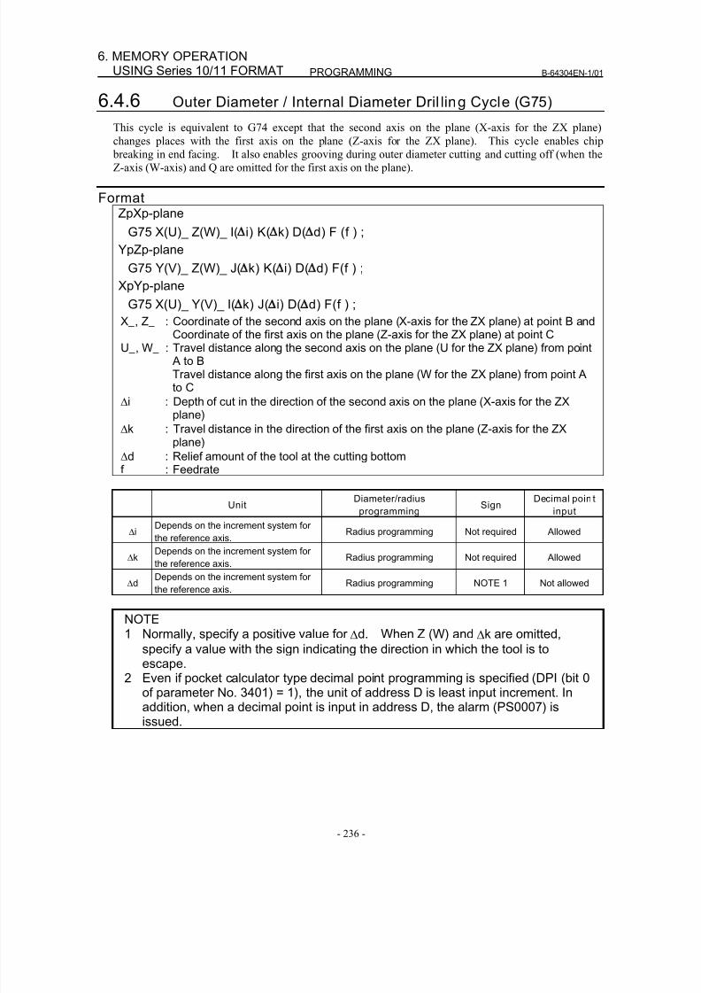
8/16/2019 Manual Operacion para FANUC
http://slidepdf.com/reader/full/manual-operacion-para-fanuc 254/435
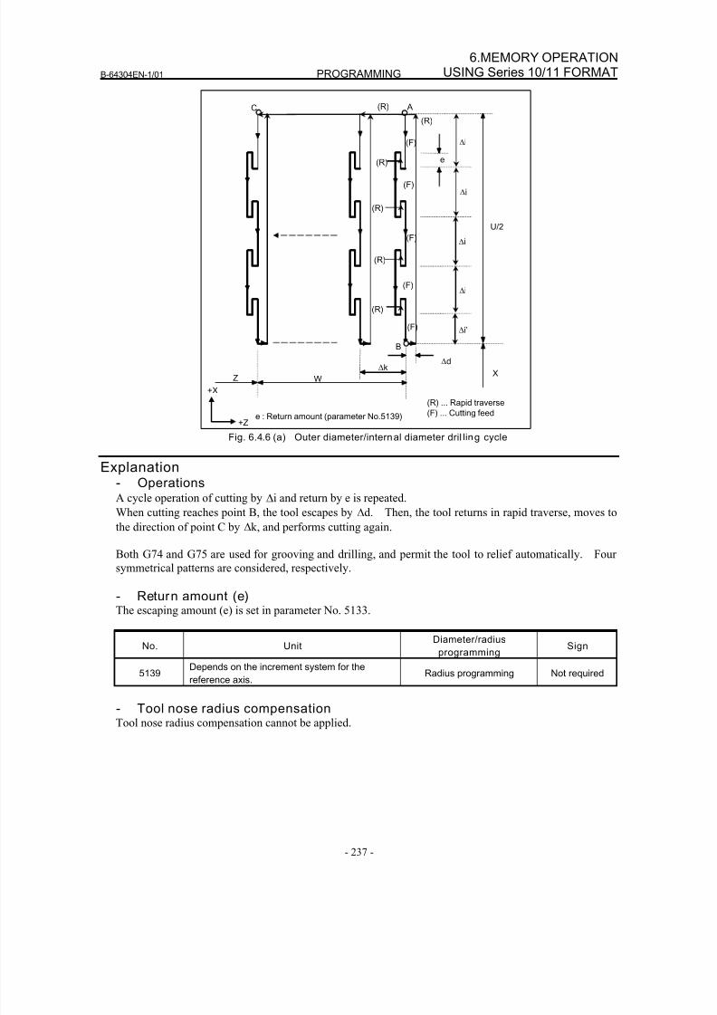
8/16/2019 Manual Operacion para FANUC
http://slidepdf.com/reader/full/manual-operacion-para-fanuc 255/435
B-64304EN-1/01 PROGRAMMING
- 237 -
6.MEMORY OPERATIONUSING Series 10/11 FORMAT
W
Δd
A
(R)
(F) Δi
e
Z
Δk X
(F)
(F)
(R)
(F)
(R)
(R)
(F)
(R)
U/2
(R) ... Rapid traverse
(F) ... Cutting feed
(R)
B
C
Δi
Δi
Δi
+X
+Z
Δi’
e : Return amount (parameter No.5139)
Fig. 6.4.6 (a) Outer diameter/internal diameter dril ling cycle
Explanation- OperationsA cycle operation of cutting by Δi and return by e is repeated.
When cutting reaches point B, the tool escapes by Δd. Then, the tool returns in rapid traverse, moves to
the direction of point C by Δk, and performs cutting again.
Both G74 and G75 are used for grooving and drilling, and permit the tool to relief automatically. Four
symmetrical patterns are considered, respectively.
- Return amount (e)The escaping amount (e) is set in parameter No. 5133.
No. Unit Diameter/radiusprogramming
Sign
5139Depends on the increment system for the
reference axis.Radius programming Not required
- Tool nose radius compensationTool nose radius compensation cannot be applied.
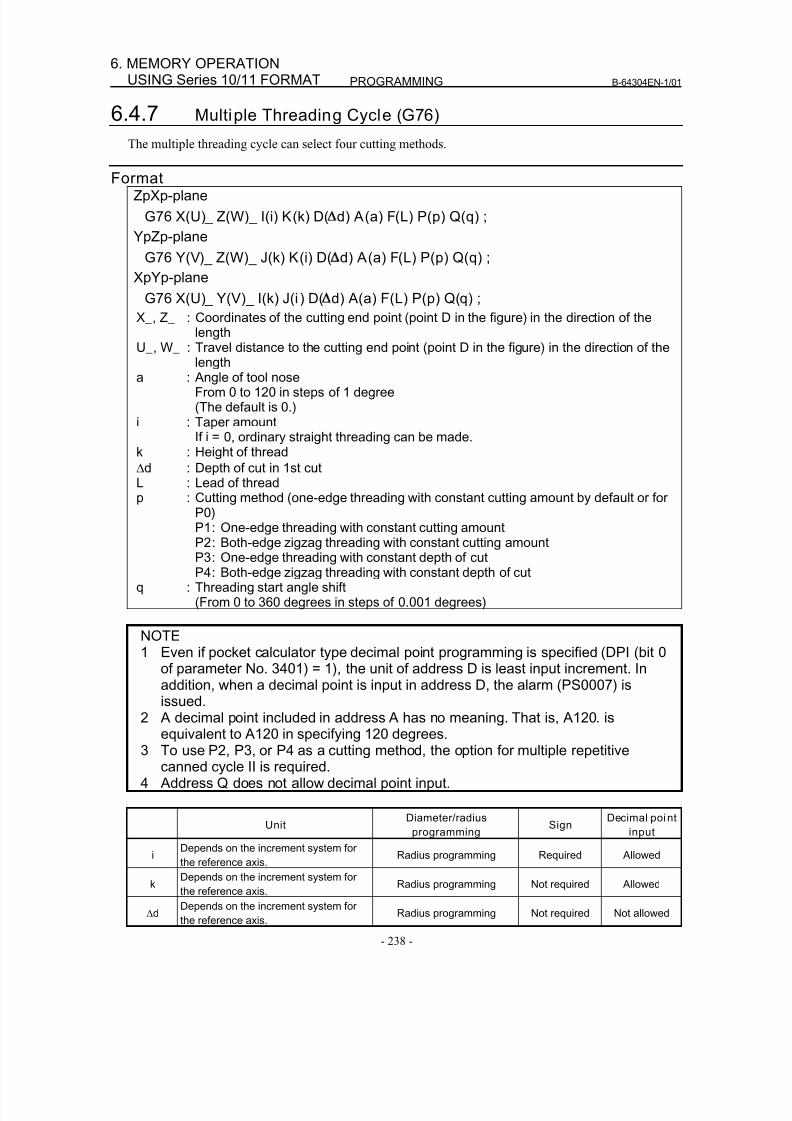
8/16/2019 Manual Operacion para FANUC
http://slidepdf.com/reader/full/manual-operacion-para-fanuc 256/435
PROGRAMMING B-64304EN-1/01
- 238 -
6. MEMORY OPERATIONUSING Series 10/11 FORMAT
6.4.7 Multiple Threading Cycle (G76)
The multiple threading cycle can select four cutting methods.
FormatZpXp-plane
G76 X(U)_ Z(W)_ I(i) K(k) D( d) A(a) F(L) P(p) Q(q) ;
YpZp-plane
G76 Y(V)_ Z(W)_ J(k) K(i) D( d) A(a) F(L) P(p) Q(q) ;
XpYp-plane
G76 X(U)_ Y(V)_ I(k) J(i ) D( d) A(a) F(L) P(p) Q(q) ;
X_, Z_ : Coordinates of the cutting end point (point D in the figure) in the direction of thelength
U_, W_ : Travel distance to the cutting end point (point D in the figure) in the direction of thelengtha : Angle of tool nose
From 0 to 120 in steps of 1 degree(The default is 0.)
i : Taper amountIf i = 0, ordinary straight threading can be made.
k : Height of thread
Δd : Depth of cut in 1st cutL : Lead of threadp : Cutting method (one-edge threading with constant cutting amount by default or for
P0)
P1 : One-edge threading with constant cutting amountP2 : Both-edge zigzag threading with constant cutting amountP3 : One-edge threading with constant depth of cutP4 : Both-edge zigzag threading with constant depth of cut
q : Threading start angle shift(From 0 to 360 degrees in steps of 0.001 degrees)
NOTE1 Even if pocket calculator type decimal point programming is specified (DPI (bit 0
of parameter No. 3401) = 1), the unit of address D is least input increment. Inaddition, when a decimal point is input in address D, the alarm (PS0007) is
issued.2 A decimal point included in address A has no meaning. That is, A120. is
equivalent to A120 in specifying 120 degrees.3 To use P2, P3, or P4 as a cutting method, the option for multiple repetitive
canned cycle II is required.4 Address Q does not allow decimal point input.
UnitDiameter/radius
programmingSign
Decimal point
input
iDepends on the increment system for
the reference axis.Radius programming Required Allowed
k Depends on the increment system forthe reference axis.
Radius programming Not required Allowed
ΔdDepends on the increment system for
the reference axis.Radius programming Not required Not allowed
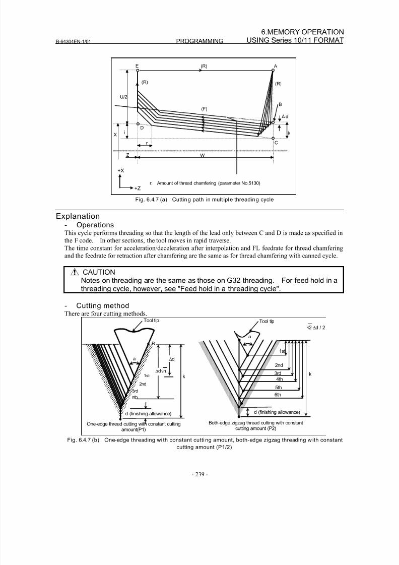
8/16/2019 Manual Operacion para FANUC
http://slidepdf.com/reader/full/manual-operacion-para-fanuc 257/435
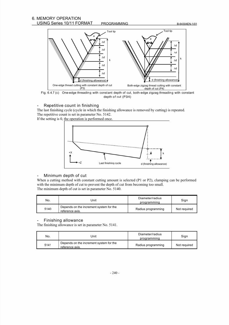
8/16/2019 Manual Operacion para FANUC
http://slidepdf.com/reader/full/manual-operacion-para-fanuc 258/435
PROGRAMMING B-64304EN-1/01
- 240 -
6. MEMORY OPERATIONUSING Series 10/11 FORMAT
Δd
k
d (finishing allowance)
a
Δd
Δd
Δd
Δd
One-edge thread cutting with constant depth of cut(P3)
d (finishing allowance)
a
Δd
Δd
Δd
Δd
k
Both-edge zigzag thread cutting with constantdepth of cut (P4)
Tool tip Tool tip
Fig. 6.4.7 (c) One-edge threading with constant depth of cut, both-edge zigzag threading with constant
depth o f cut (P3/4)
- Repetitive count in finishingThe last finishing cycle (cycle in which the finishing allowance is removed by cutting) is repeated.
The repetitive count is set in parameter No. 5142.
If the setting is 0, the operation is performed once.
+X
+Z
k
d (finishing allowance)Last finishing cycle
- Minimum depth of cutWhen a cutting method with constant cutting amount is selected (P1 or P2), clamping can be performed
with the minimum depth of cut to prevent the depth of cut from becoming too small.
The minimum depth of cut is set in parameter No. 5140.
No. UnitDiameter/radius
programmingSign
5140Depends on the increment system for the
reference axis.Radius programming Not required
- Finishing allowanceThe finishing allowance is set in parameter No. 5141.
No. UnitDiameter/radius
programmingSign
5141Depends on the increment system for the
reference axis.Radius programming Not required
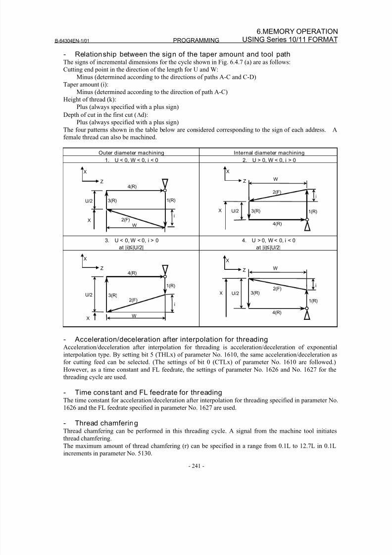
8/16/2019 Manual Operacion para FANUC
http://slidepdf.com/reader/full/manual-operacion-para-fanuc 259/435
B-64304EN-1/01 PROGRAMMING
- 241 -
6.MEMORY OPERATIONUSING Series 10/11 FORMAT
- Relationship between the sign of the taper amount and tool pathThe signs of incremental dimensions for the cycle shown in Fig. 6.4.7 (a) are as follows:
Cutting end point in the direction of the length for U and W:
Minus (determined according to the directions of paths A-C and C-D)
Taper amount (i):Minus (determined according to the direction of path A-C)
Height of thread (k):
Plus (always specified with a plus sign)
Depth of cut in the first cut (Δd):
Plus (always specified with a plus sign)
The four patterns shown in the table below are considered corresponding to the sign of each address. A
female thread can also be machined.
Outer diameter machining Internal diameter machining
1. U < 0, W < 0, i < 0 2. U > 0, W < 0, i > 0
XZ
U/2
3(R)
4(R)
1(R)
2(F)
W
iX
X
Z
U/2 3(R)
4(R)
1(R)
2(F)
W
i
X
3. U < 0, W < 0, i > 0
at |i| |U/2|
4. U > 0, W < 0, i < 0
at |i| |U/2|
X
Z
U/2 3(R)
4(R)
1(R)
2(F)
W
i
X
X
Z
U/2 3(R)
4(R)
1(R)
2(F)
W
i
X
- Acceleration/deceleration after interpolation for threading
Acceleration/deceleration after interpolation for threading is acceleration/deceleration of exponentialinterpolation type. By setting bit 5 (THLx) of parameter No. 1610, the same acceleration/deceleration as
for cutting feed can be selected. (The settings of bit 0 (CTLx) of parameter No. 1610 are followed.)
However, as a time constant and FL feedrate, the settings of parameter No. 1626 and No. 1627 for the
threading cycle are used.
- Time constant and FL feedrate for threadingThe time constant for acceleration/deceleration after interpolation for threading specified in parameter No.
1626 and the FL feedrate specified in parameter No. 1627 are used.
- Thread chamferingThread chamfering can be performed in this threading cycle. A signal from the machine tool initiates
thread chamfering.
The maximum amount of thread chamfering (r) can be specified in a range from 0.1L to 12.7L in 0.1L
increments in parameter No. 5130.
8/16/2019 Manual Operacion para FANUC
http://slidepdf.com/reader/full/manual-operacion-para-fanuc 260/435
PROGRAMMING B-64304EN-1/01
- 242 -
6. MEMORY OPERATIONUSING Series 10/11 FORMAT
A thread chamfering angle between 1 to 89 degrees can be specified in parameter No. 5131. When a
value of 0 is specified in the parameter, an angle of 45 degrees is assumed.
For thread chamfering, the same type of acceleration/deceleration after interpolation, time constant for
acceleration/deceleration after interpolation, and FL feedrate as for threading are used.
NOTECommon parameters for specifying the amount and angle of thread chamferingare used for this cycle and G92 threading cycle.
- Retraction after chamferingThe following table lists the feedrate, type of acceleration/deceleration after interpolation, and time
constant of retraction after chamfering.
Parameter CFR (No.
1611#0)
Parameter No.
1466Description
0 Other than 0 Uses the type of acceleration/deceleration after interpolation for threading,
time constant for threading (parameter No. 1626), FL feedrate (parameter
No. 1627), and retraction feedrate specified in parameter No. 1466.
0 0 Uses the type of acceleration/deceleration after interpolation for threading,
time constant for threading (parameter No. 1626), FL feedrate (parameter
No. 1627), and rapid traverse rate specified in parameter No. 1420.
1 Before retraction a check is made to see that the specified feedrate has
become 0 (delay in acceleration/deceleration is 0), and the type of
acceleration/deceleration after interpolation for rapid traverse is used
together with the rapid traverse time constant and the rapid traverse rate
(parameter No. 1420).
By setting bit 4 (ROC) of parameter No. 1403 to 1, rapid traverse override can be disabled for the feedrate
of retraction after chamfering.
NOTEDuring retraction, the machine does not stop with an override of 0% for thecutting feedrate regardless of the setting of bit 4 (RF0) of parameter No. 1401.
- Shifting the start angleAddress Q can be used to shift the start angle of threading.
The start angle (Q) increment is 0.001 degrees and the valid setting range is between 0 and 360 degrees.
No decimal point can be specified.
- Feed hold when the threading cycle retract function is usedFeed hold may be applied during threading in a multiple threading cycle (G76). In this case, the tool
quickly retracts in the same way as for the last chamfering in a threading cycle and returns to the start
point in the current cycle (position where the workpiece is cut by Δdn).
When cycle start is triggered, the multiple threading cycle resumes.
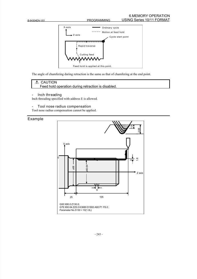
8/16/2019 Manual Operacion para FANUC
http://slidepdf.com/reader/full/manual-operacion-para-fanuc 261/435
B-64304EN-1/01 PROGRAMMING
- 243 -
6.MEMORY OPERATIONUSING Series 10/11 FORMAT
Feed ho ld is applied at this point.
Cycle start point
Ordinary cycle
Rapid traverse
Motion at feed hold
Cutting feed
X-axis
Z-axis
The angle of chamfering during retraction is the same as that of chamfering at the end point.
CAUTION
Feed hold operation during retraction is disabled.
- Inch threadingInch threading specified with address E is allowed.
- Tool nose radius compensationTool nose radius compensation cannot be applied.
Example
G00 X80.0 Z130.0;
G76 X60.64 Z25.0 K3680 D1800 A60 P1 F6.0 ;
Parameter No.5130 = 10(1.0L)
1 .
8
3 .
6 8
6
Z axis
10525
ϕ 6 0 .
6 4
1 .
8
X axis
0
ϕ 6 8
8/16/2019 Manual Operacion para FANUC
http://slidepdf.com/reader/full/manual-operacion-para-fanuc 262/435
PROGRAMMING B-64304EN-1/01
- 244 -
6. MEMORY OPERATIONUSING Series 10/11 FORMAT
6.4.8 Restrict ions on Multiple Repetitive Canned Cycle
Programmed commands- Program memoryPrograms using G70, G71, G72, or G73 must be stored in the program memory. The use of the mode in
which programs stored in the program memory are called for operation enables these programs to be
executed in other than the MEM mode. Programs using G74, G75, or G76 need not be stored in the
program memory.
- Blocks in which data related to a multiple repetitive canned cycle is specifiedThe addresses P, Q, X, Z, U, W, and R should be specified correctly for each block.
In a block in which G70, G71, G72, or G73 is specified, the following functions cannot be specified:
• Custom macro calls
(simple call, modal call, and subprogram call)
- Blocks in which data related to a target figure is specifiedIn the block which is specified by address P of a G71, G72 or G73, G00 or G01 code in group 01 should
be commanded. If it is not commanded, alarm PS0065 is generated.
In blocks with sequence numbers between those specified at P and Q in G70, G71, G72, and G73, the
following commands can be specified:
• Dwell (G04)
• G00, G01, G02, and G03
When a circular interpolation command (G02, G03) is used, there must be no radius difference
between the start point and end point of the arc. If there is a radius difference, the target finishing
figure may not be recognized correctly, resulting in a cutting error such as excessive cutting.
• Custom macro branch and repeat commandThe branch destination must be between the sequence numbers specified at P and Q, however.
High-speed branch specified by bits 1 and 4 of parameter No. 6000 is invalid. No custom macro
call (simple, modal, or subprogram call) cannot be specified.
• Direct drawing dimension programming command and chamfering and corner R command
Direct drawing dimension programming and chamfering and corner R require multiple blocks to be
specified. The block with the last sequence number specified at Q must not be an intermediate
block of these specified blocks.
When G70, G71, G72, or G73 is executed, the sequence number specified by address P and Q should not
be specified twice or more in the same program.
When #1 = 2500 is executed using a custom macro, 2500.000 is assigned to #1. In such a case, P#1 is
equivalent to P2500.
Relation with other functions- Manual interventionWhile a multiple repetitive canned cycle (G70 to G76) is being executed, it is possible to stop the cycle
and to perform manual intervention.
The setting of manual absolute on or off is effective for manual operation.
- Interruption type macroAny interruption type macro program cannot be executed during execution of a multiple repetitive canned
cycle.
- Program restart and tool retract and recoverThese functions cannot be executed in a block in a multiple repetitive canned cycle.
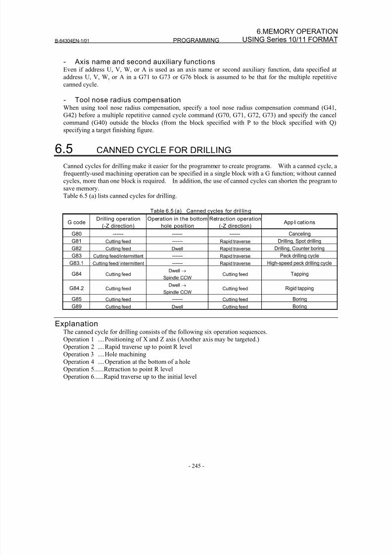
8/16/2019 Manual Operacion para FANUC
http://slidepdf.com/reader/full/manual-operacion-para-fanuc 263/435
B-64304EN-1/01 PROGRAMMING
- 245 -
6.MEMORY OPERATIONUSING Series 10/11 FORMAT
- Axis name and second auxiliary functionsEven if address U, V, W, or A is used as an axis name or second auxiliary function, data specified at
address U, V, W, or A in a G71 to G73 or G76 block is assumed to be that for the multiple repetitive
canned cycle.
- Tool nose radius compensationWhen using tool nose radius compensation, specify a tool nose radius compensation command (G41,
G42) before a multiple repetitive canned cycle command (G70, G71, G72, G73) and specify the cancel
command (G40) outside the blocks (from the block specified with P to the block specified with Q)
specifying a target finishing figure.
6.5 CANNED CYCLE FOR DRILLING
Canned cycles for drilling make it easier for the programmer to create programs. With a canned cycle, a
frequently-used machining operation can be specified in a single block with a G function; without cannedcycles, more than one block is required. In addition, the use of canned cycles can shorten the program to
save memory.
Table 6.5 (a) lists canned cycles for drilling.
Table 6.5 (a) Canned cycles for dril ling
G codeDrilling operation
(-Z direction)
Operation in the bottom
hole position
Retraction operation
(-Z direction) App lications
G80 ------ ------ ------ Canceling
G81 Cutting feed ------ Rapid traverse Drilling, Spot drilling
G82 Cutting feed Dwell Rapid traverse Drilling, Counter boring
G83 Cutting feed/intermittent ------ Rapid traverse Peck drilling cycle
G83.1 Cutting feed/ intermittent ------ Rapid traverse High-speed peck drilling cycle
G84 Cutting feed Dwell →
Spindle CCW Cutting feed Tapping
G84.2 Cutting feed Dwell →
Spindle CCW Cutting feed Rigid tapping
G85 Cutting feed ------ Cutting feed Boring
G89 Cutting feed Dwell Cutting feed Boring
ExplanationThe canned cycle for drilling consists of the following six operation sequences.
Operation 1 ....Positioning of X and Z axis (Another axis may be targeted.)
Operation 2 ....Rapid traverse up to point R levelOperation 3 ....Hole machining
Operation 4 ....Operation at the bottom of a hole
Operation 5......Retraction to point R level
Operation 6......Rapid traverse up to the initial level
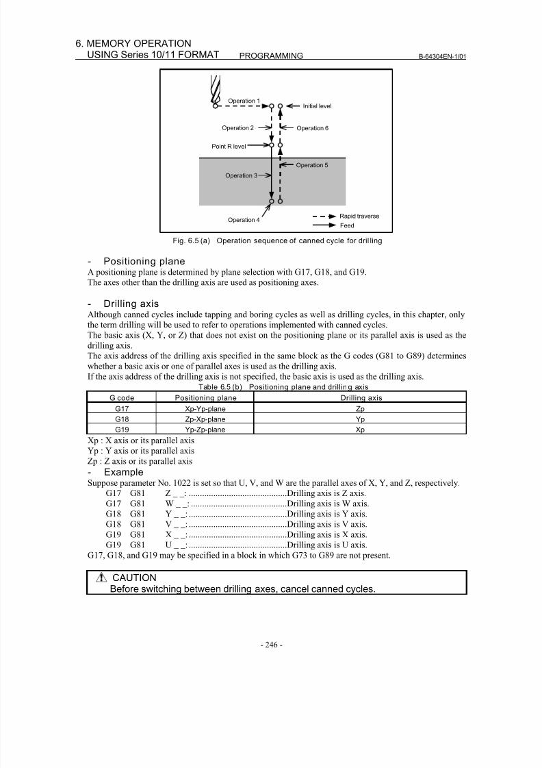
8/16/2019 Manual Operacion para FANUC
http://slidepdf.com/reader/full/manual-operacion-para-fanuc 264/435
PROGRAMMING B-64304EN-1/01
- 246 -
6. MEMORY OPERATIONUSING Series 10/11 FORMAT
Operation 1
Operation 2
Point R level
Initial level
Operation 6
Operation 5
Operation 3
Operation 4Rapid traverse
Feed
Fig. 6.5 (a) Operation sequence of canned cycle for dril ling
- Positioning planeA positioning plane is determined by plane selection with G17, G18, and G19.
The axes other than the drilling axis are used as positioning axes.
- Drilling axisAlthough canned cycles include tapping and boring cycles as well as drilling cycles, in this chapter, only
the term drilling will be used to refer to operations implemented with canned cycles.
The basic axis (X, Y, or Z) that does not exist on the positioning plane or its parallel axis is used as the
drilling axis.
The axis address of the drilling axis specified in the same block as the G codes (G81 to G89) determines
whether a basic axis or one of parallel axes is used as the drilling axis.
If the axis address of the drilling axis is not specified, the basic axis is used as the drilling axis.Table 6.5 (b) Positioning plane and drilling axis
G code Positioning plane Drilling axis
G17 Xp-Yp-plane Zp
G18 Zp-Xp-plane Yp
G19 Yp-Zp-plane Xp
Xp : X axis or its parallel axis
Yp : Y axis or its parallel axis
Zp : Z axis or its parallel axis
- Example
Suppose parameter No. 1022 is set so that U, V, and W are the parallel axes of X, Y, and Z, respectively.G17 G81 Z _ _: ............................................Drilling axis is Z axis.
G17 G81 W _ _: ...........................................Drilling axis is W axis.
G18 G81 Y _ _: ............................................Drilling axis is Y axis.
G18 G81 V _ _: ............................................Drilling axis is V axis.
G19 G81 X _ _: ............................................Drilling axis is X axis.
G19 G81 U _ _: ............................................Drilling axis is U axis.
G17, G18, and G19 may be specified in a block in which G73 to G89 are not present.
CAUTIONBefore switching between drilling axes, cancel canned cycles.
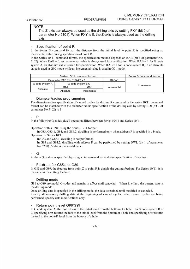
8/16/2019 Manual Operacion para FANUC
http://slidepdf.com/reader/full/manual-operacion-para-fanuc 265/435
B-64304EN-1/01 PROGRAMMING
- 247 -
6.MEMORY OPERATIONUSING Series 10/11 FORMAT
NOTEThe Z-axis can always be used as the drilling axis by setting FXY (bit 0 ofparameter No.5101). When FXY is 0, the Z-axis is always used as the drillingaxis.
- Specification of point RIn the Series 0i command format, the distance from the initial level to point R is specified using an
incremental value during specification of point R.
In the Series 10/11 command format, the specification method depends on RAB (bit 6 of parameter No.
5102). When RAB = 0, an incremental value is always used for specification. When RAB = 1 for G code
system A, an absolute value is used for specification. When RAB = 1 for G code system B, C, an absolute
value is used in G90 mode while an incremental value is used in G91 mode.
Series 10/11 command format Series 0i command format
Parameter RAB (No.5102#6) = 1 RAB=0
G code system A G code system B,CG90 G91
Absolute Absolute Incremental
IncrementalIncremental
- Diameter/radius programmingThe diameter/radius specification of canned cycles for drilling R command in the series 10/11 command
format can be matched with the diameter/radius specification of the drilling axis by setting RDI (bit 7 of
parameter No.5102) to 1.
- PIn the following G codes, dwell operation differs between Series 10/11 and Series 10/11.
Operation of this CNC using the Series 10/11 format
In G83, G83.1, G84, and G84.2, dwelling is performed only when address P is specified in a block.
Operation of Series 10/11
In G83 and G83.1, dwelling is not performed.
In G84 and G84.2, dwelling with address P can be performed by setting DWL (bit 1 of parameter
No.6200). Address P is modal data.
- QAddress Q is always specified by using an incremental value during specification of a radius.
- Feedrate for G85 and G89
In G85 and G89, the feedrate from point Z to point R is double the cutting feedrate. For Series 10/11, it isthe same as the cutting feedrate.
- Drilling modeG81 to G89 are modal G codes and remain in effect until canceled. When in effect, the current state is
the drilling mode.
Once drilling data is specified in the drilling mode, the data is retained until modified or canceled.
Specify all necessary drilling data at the beginning of canned cycles; when canned cycles are being
performed, specify data modifications only.
- Return point level G98/G99In G code system A, the tool returns to the initial level from the bottom of a hole. In G code system B or
C, specifying G98 returns the tool to the initial level from the bottom of a hole and specifying G99 returns
the tool to the point-R level from the bottom of a hole.
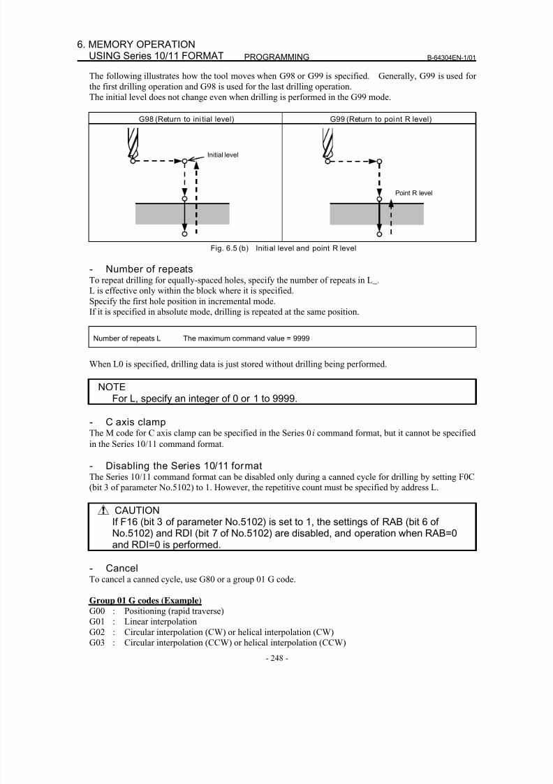
8/16/2019 Manual Operacion para FANUC
http://slidepdf.com/reader/full/manual-operacion-para-fanuc 266/435
PROGRAMMING B-64304EN-1/01
- 248 -
6. MEMORY OPERATIONUSING Series 10/11 FORMAT
The following illustrates how the tool moves when G98 or G99 is specified. Generally, G99 is used for
the first drilling operation and G98 is used for the last drilling operation.
The initial level does not change even when drilling is performed in the G99 mode.
G98 (Return to ini tial level) G99 (Return to point R level)
Initial level
Point R level
Fig. 6.5 (b) Initial level and point R level
- Number of repeatsTo repeat drilling for equally-spaced holes, specify the number of repeats in L_.
L is effective only within the block where it is specified.
Specify the first hole position in incremental mode.
If it is specified in absolute mode, drilling is repeated at the same position.
Number of repeats L The maximum command value = 9999
When L0 is specified, drilling data is just stored without drilling being performed.
NOTEFor L, specify an integer of 0 or 1 to 9999.
- C axis clampThe M code for C axis clamp can be specified in the Series 0i command format, but it cannot be specified
in the Series 10/11 command format.
- Disabling the Series 10/11 formatThe Series 10/11 command format can be disabled only during a canned cycle for drilling by setting F0C
(bit 3 of parameter No.5102) to 1. However, the repetitive count must be specified by address L.
CAUTIONIf F16 (bit 3 of parameter No.5102) is set to 1, the settings of RAB (bit 6 ofNo.5102) and RDI (bit 7 of No.5102) are disabled, and operation when RAB=0and RDI=0 is performed.
- CancelTo cancel a canned cycle, use G80 or a group 01 G code.
Group 01 G codes (Example)
G00 : Positioning (rapid traverse)
G01 : Linear interpolation
G02 : Circular interpolation (CW) or helical interpolation (CW)
G03 : Circular interpolation (CCW) or helical interpolation (CCW)
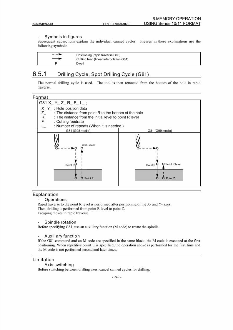
8/16/2019 Manual Operacion para FANUC
http://slidepdf.com/reader/full/manual-operacion-para-fanuc 267/435
B-64304EN-1/01 PROGRAMMING
- 249 -
6.MEMORY OPERATIONUSING Series 10/11 FORMAT
- Symbols in figuresSubsequent subsections explain the individual canned cycles. Figures in these explanations use the
following symbols:
Positioning (rapid traverse G00)
Cutting feed (linear interpolation G01)
P Dwell
6.5.1 Drilling Cycle, Spot Drilling Cycle (G81)
The normal drilling cycle is used. The tool is then retracted from the bottom of the hole in rapid
traverse.
Format
G81 X_ Y_ Z_ R_ F_ L_ ;X_ Y_ : Hole position dataZ_ : The distance from point R to the bottom of the holeR_ : The distance from the initial level to point R levelF_ : Cutting feedrateL_ : Number of repeats (When it is needed.)
G81 (G98 mode) G81 (G99 mode)
Initial level
Point R
Point Z
Point R levelPoint R
Point Z
Explanation- OperationsRapid traverse to the point R level is performed after positioning of the X- and Y- axes.
Then, drilling is performed from point R level to point Z.Escaping moves in rapid traverse.
- Spindle rotationBefore specifying G81, use an auxiliary function (M code) to rotate the spindle.
- Auxiliary functionIf the G81 command and an M code are specified in the same block, the M code is executed at the first
positioning. When repetitive count L is specified, the operation above is performed for the first time and
the M code is not performed second and later times.
Limitation- Axis switchingBefore switching between drilling axes, cancel canned cycles for drilling.
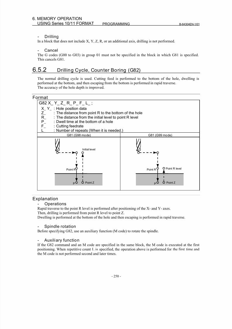
8/16/2019 Manual Operacion para FANUC
http://slidepdf.com/reader/full/manual-operacion-para-fanuc 268/435
PROGRAMMING B-64304EN-1/01
- 250 -
6. MEMORY OPERATIONUSING Series 10/11 FORMAT
- DrillingIn a block that does not include X, Y, Z, R, or an additional axis, drilling is not performed.
- CancelThe G codes (G00 to G03) in group 01 must not be specified in the block in which G81 is specified.
This cancels G81.
6.5.2 Drilling Cycle, Counter Boring (G82)
The normal drilling cycle is used. Cutting feed is performed to the bottom of the hole, dwelling is
performed at the bottom, and then escaping from the bottom is performed in rapid traverse.
The accuracy of the hole depth is improved.
Format
G82 X_ Y_ Z_ R_ P_ F_ L_ ;X_ Y_ : Hole position dataZ_ : The distance from point R to the bottom of the holeR_ : The distance from the initial level to point R levelP_ : Dwell time at the bottom of a holeF_ : Cutting feedrateL_ : Number of repeats (When it is needed.)
G81 (G98 mode) G81 (G99 mode)
Initial level
Point R
Point ZP
Point R levelPoint R
Point ZP
Explanation- OperationsRapid traverse to the point R level is performed after positioning of the X- and Y- axes.
Then, drilling is performed from point R level to point Z.
Dwelling is performed at the bottom of the hole and then escaping is performed in rapid traverse.
- Spindle rotationBefore specifying G82, use an auxiliary function (M code) to rotate the spindle.
- Auxiliary functionIf the G82 command and an M code are specified in the same block, the M code is executed at the first
positioning. When repetitive count L is specified, the operation above is performed for the first time and
the M code is not performed second and later times.
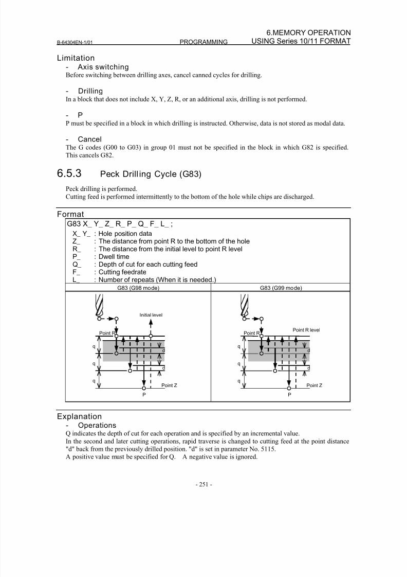
8/16/2019 Manual Operacion para FANUC
http://slidepdf.com/reader/full/manual-operacion-para-fanuc 269/435
B-64304EN-1/01 PROGRAMMING
- 251 -
6.MEMORY OPERATIONUSING Series 10/11 FORMAT
Limitation- Axis switchingBefore switching between drilling axes, cancel canned cycles for drilling.
- DrillingIn a block that does not include X, Y, Z, R, or an additional axis, drilling is not performed.
- PP must be specified in a block in which drilling is instructed. Otherwise, data is not stored as modal data.
- CancelThe G codes (G00 to G03) in group 01 must not be specified in the block in which G82 is specified.
This cancels G82.
6.5.3 Peck Drill ing Cycle (G83)
Peck drilling is performed.
Cutting feed is performed intermittently to the bottom of the hole while chips are discharged.
Format
G83 X_ Y_ Z_ R_ P_ Q_ F_ L_ ;
X_ Y_ : Hole position dataZ_ : The distance from point R to the bottom of the holeR_ : The distance from the initial level to point R levelP_ : Dwell timeQ_ : Depth of cut for each cutting feed
F_ : Cutting feedrateL_ : Number of repeats (When it is needed.)
G83 (G98 mode) G83 (G99 mode)
Point R
q
q
q
d
Point Z
Initial level
d
P
Point R
q
q
q
d
Point Z
Point R level
d
P
Explanation- OperationsQ indicates the depth of cut for each operation and is specified by an incremental value.
In the second and later cutting operations, rapid traverse is changed to cutting feed at the point distance
"d" back from the previously drilled position. "d" is set in parameter No. 5115.
A positive value must be specified for Q. A negative value is ignored.
8/16/2019 Manual Operacion para FANUC
http://slidepdf.com/reader/full/manual-operacion-para-fanuc 270/435
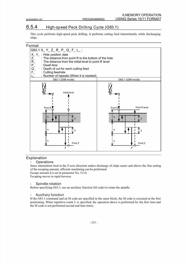
8/16/2019 Manual Operacion para FANUC
http://slidepdf.com/reader/full/manual-operacion-para-fanuc 271/435
B-64304EN-1/01 PROGRAMMING
- 253 -
6.MEMORY OPERATIONUSING Series 10/11 FORMAT
6.5.4 High-speed Peck Dri lling Cycle (G83.1)
This cycle performs high-speed peck drilling. It performs cutting feed intermittently while discharging
chips.
FormatG83.1 X_ Y_ Z_ R_ P_ Q_ F_ L_ ;
X_ Y_ : Hole position dataZ_ : The distance from point R to the bottom of the holeR_ : The distance from the initial level to point R levelP_ : Dwell timeQ_ : Depth of cut for each cutting feedF_ : Cutting feedrateL_ : Number of repeats (When it is needed)
G83.1 (G98 mode) G83.1 (G99 mode)
P
Point R
q
q
q
d
d
Point Z
Initial level
Point R levelPoint R
q
q
q
d
d
Point Z
P
Explanation- Operations
Since intermittent feed in the Z-axis direction makes discharge of chips easier and allows the fine settingof the escaping amount, efficient machining can be performed.
Escape amount d is set in parameter No. 5114.
Escaping moves in rapid traverse.
- Spindle rotationBefore specifying G83.1, use an auxiliary function (M code) to rotate the spindle.
- Auxiliary functionIf the G83.1 command and an M code are specified in the same block, the M code is executed at the first
positioning. When repetitive count L is specified, the operation above is performed for the first time and
the M code is not performed second and later times.
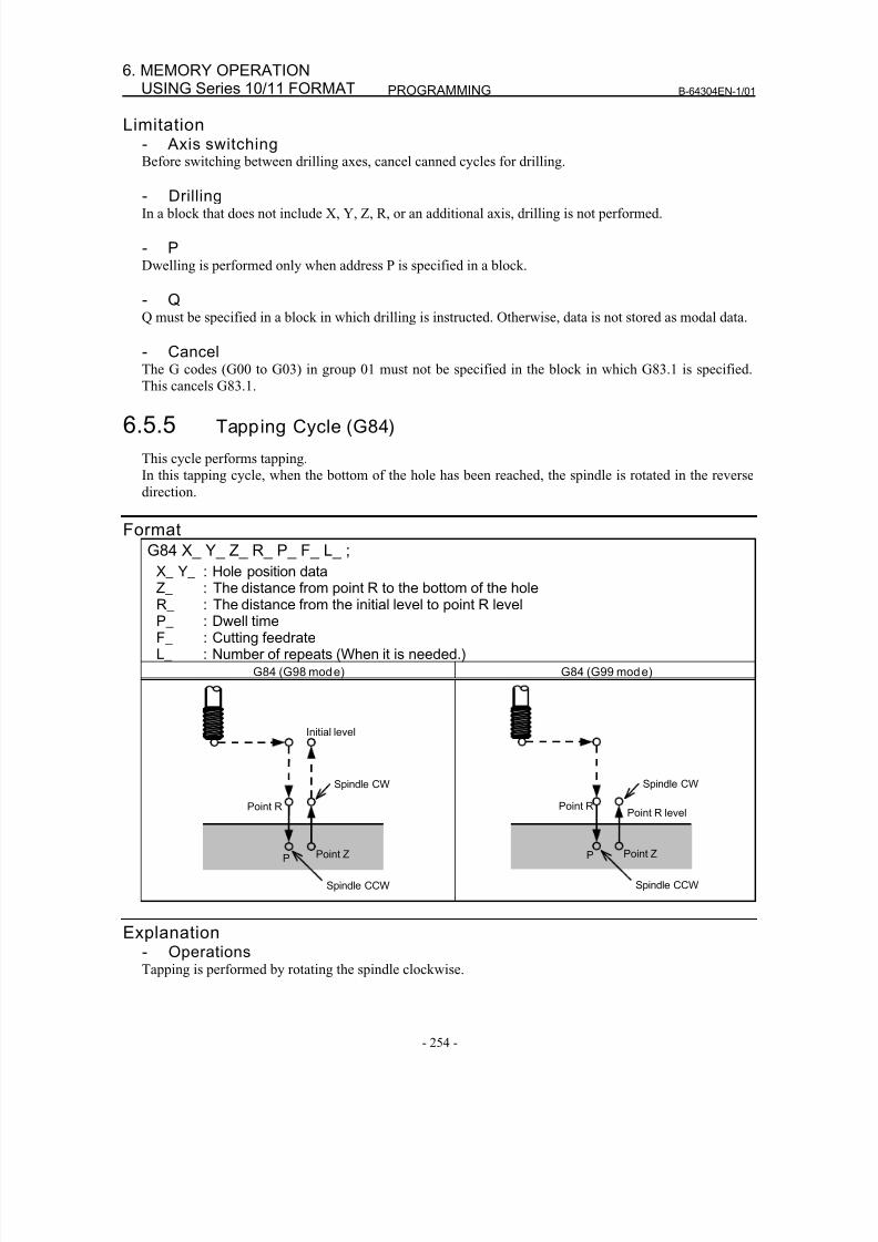
8/16/2019 Manual Operacion para FANUC
http://slidepdf.com/reader/full/manual-operacion-para-fanuc 272/435
PROGRAMMING B-64304EN-1/01
- 254 -
6. MEMORY OPERATIONUSING Series 10/11 FORMAT
Limitation- Axis switchingBefore switching between drilling axes, cancel canned cycles for drilling.
- DrillingIn a block that does not include X, Y, Z, R, or an additional axis, drilling is not performed.
- PDwelling is performed only when address P is specified in a block.
- QQ must be specified in a block in which drilling is instructed. Otherwise, data is not stored as modal data.
- CancelThe G codes (G00 to G03) in group 01 must not be specified in the block in which G83.1 is specified.
This cancels G83.1.
6.5.5 Tapping Cycle (G84)
This cycle performs tapping.
In this tapping cycle, when the bottom of the hole has been reached, the spindle is rotated in the reverse
direction.
Format
G84 X_ Y_ Z_ R_ P_ F_ L_ ;
X_ Y_ : Hole position data
Z_ : The distance from point R to the bottom of the holeR_ : The distance from the initial level to point R levelP_ : Dwell timeF_ : Cutting feedrateL_ : Number of repeats (When it is needed.)
G84 (G98 mode) G84 (G99 mode)
Point R
Point Z
Spindle CCW
Spindle CW
Initial level
P
Point R
Point Z
Spindle CCW
Spindle CW
Point R level
P
Explanation- Operations
Tapping is performed by rotating the spindle clockwise.
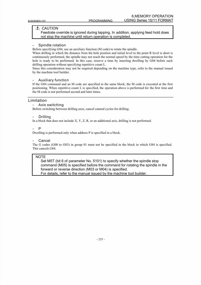
8/16/2019 Manual Operacion para FANUC
http://slidepdf.com/reader/full/manual-operacion-para-fanuc 273/435
B-64304EN-1/01 PROGRAMMING
- 255 -
6.MEMORY OPERATIONUSING Series 10/11 FORMAT
CAUTIONFeedrate override is ignored during tapping. In addition, applying feed hold doesnot stop the machine until return operation is completed.
- Spindle rotationBefore specifying G84, use an auxiliary function (M code) to rotate the spindle.
When drilling in which the distance from the hole position and initial level to the point R level is short is
continuously performed, the spindle may not reach the normal speed by the time cutting operation for the
hole is ready to be performed. In this case, reserve a time by inserting dwelling by G04 before each
drilling operation without specifying repetitive count L.
Since this consideration may not be required depending on the machine type, refer to the manual issued
by the machine tool builder.
- Auxiliary functionIf the G84 command and an M code are specified in the same block, the M code is executed at the first
positioning. When repetitive count L is specified, the operation above is performed for the first time andthe M code is not performed second and later times.
Limitation- Axis switchingBefore switching between drilling axes, cancel canned cycles for drilling.
- DrillingIn a block that does not include X, Y, Z, R, or an additional axis, drilling is not performed.
- P
Dwelling is performed only when address P is specified in a block.
- CancelThe G codes (G00 to G03) in group 01 must not be specified in the block in which G84 is specified.
This cancels G84.
NOTESet M5T (bit 6 of parameter No. 5101) to specify whether the spindle stopcommand (M05) is specified before the command for rotating the spindle in theforward or reverse direction (M03 or M04) is specified.For details, refer to the manual issued by the machine tool builder.
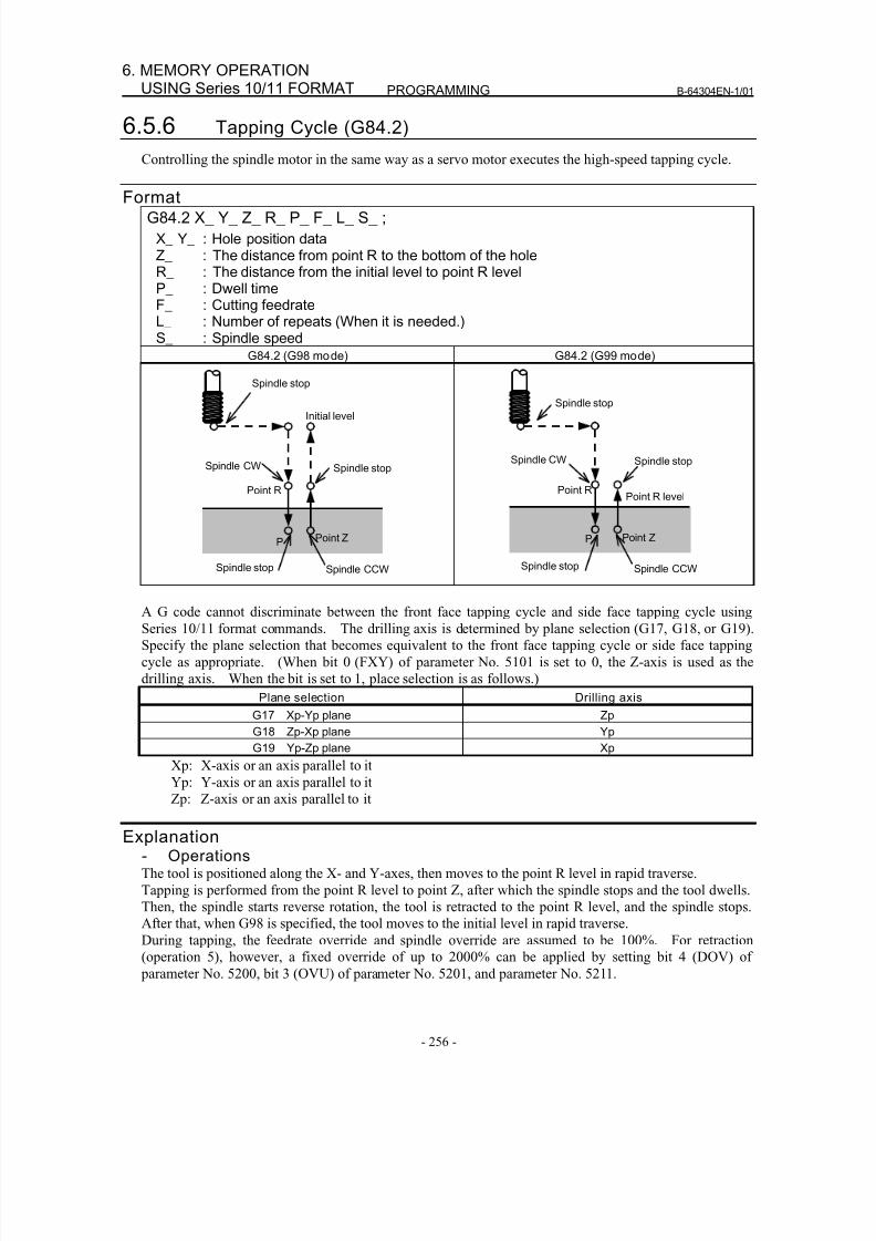
8/16/2019 Manual Operacion para FANUC
http://slidepdf.com/reader/full/manual-operacion-para-fanuc 274/435
PROGRAMMING B-64304EN-1/01
- 256 -
6. MEMORY OPERATIONUSING Series 10/11 FORMAT
6.5.6 Tapping Cycle (G84.2)
Controlling the spindle motor in the same way as a servo motor executes the high-speed tapping cycle.
FormatG84.2 X_ Y_ Z_ R_ P_ F_ L_ S_ ;
X_ Y_ : Hole position dataZ_ : The distance from point R to the bottom of the holeR_ : The distance from the initial level to point R levelP_ : Dwell timeF_ : Cutting feedrateL_ : Number of repeats (When it is needed.)S_ : Spindle speed
G84.2 (G98 mode) G84.2 (G99 mode)
Point R
Point Z
Spindle CCW
Spindle stop
Initial level
P
Spindle stop
Spindle CW
Spindle stop
Point R
Point Z
Spindle CCW
Spindle stop
Point R level
P
Spindle stop
Spindle CW
Spindle stop
A G code cannot discriminate between the front face tapping cycle and side face tapping cycle using
Series 10/11 format commands. The drilling axis is determined by plane selection (G17, G18, or G19).
Specify the plane selection that becomes equivalent to the front face tapping cycle or side face tapping
cycle as appropriate. (When bit 0 (FXY) of parameter No. 5101 is set to 0, the Z-axis is used as the
drilling axis. When the bit is set to 1, place selection is as follows.)
Plane selection Drilling axis
G17 Xp-Yp plane Zp
G18 Zp-Xp plane Yp
G19 Yp-Zp plane Xp
Xp: X-axis or an axis parallel to it
Yp: Y-axis or an axis parallel to itZp: Z-axis or an axis parallel to it
Explanation- OperationsThe tool is positioned along the X- and Y-axes, then moves to the point R level in rapid traverse.
Tapping is performed from the point R level to point Z, after which the spindle stops and the tool dwells.
Then, the spindle starts reverse rotation, the tool is retracted to the point R level, and the spindle stops.
After that, when G98 is specified, the tool moves to the initial level in rapid traverse.
During tapping, the feedrate override and spindle override are assumed to be 100%. For retraction
(operation 5), however, a fixed override of up to 2000% can be applied by setting bit 4 (DOV) of
parameter No. 5200, bit 3 (OVU) of parameter No. 5201, and parameter No. 5211.
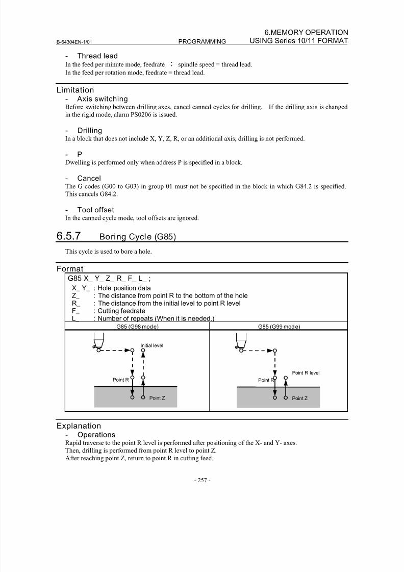
8/16/2019 Manual Operacion para FANUC
http://slidepdf.com/reader/full/manual-operacion-para-fanuc 275/435
B-64304EN-1/01 PROGRAMMING
- 257 -
6.MEMORY OPERATIONUSING Series 10/11 FORMAT
- Thread leadIn the feed per minute mode, feedrate ÷ spindle speed = thread lead.
In the feed per rotation mode, feedrate = thread lead.
Limitation- Axis switchingBefore switching between drilling axes, cancel canned cycles for drilling. If the drilling axis is changed
in the rigid mode, alarm PS0206 is issued.
- DrillingIn a block that does not include X, Y, Z, R, or an additional axis, drilling is not performed.
- PDwelling is performed only when address P is specified in a block.
- CancelThe G codes (G00 to G03) in group 01 must not be specified in the block in which G84.2 is specified.
This cancels G84.2.
- Tool offsetIn the canned cycle mode, tool offsets are ignored.
6.5.7 Boring Cycle (G85)
This cycle is used to bore a hole.
FormatG85 X_ Y_ Z_ R_ F_ L_ ;
X_ Y_ : Hole position dataZ_ : The distance from point R to the bottom of the holeR_ : The distance from the initial level to point R levelF_ : Cutting feedrateL_ : Number of repeats (When it is needed.)
G85 (G98 mode) G85 (G99 mode)
Point R
Point Z
Initial level
Point R
Point Z
Point R level
Explanation- OperationsRapid traverse to the point R level is performed after positioning of the X- and Y- axes.
Then, drilling is performed from point R level to point Z.After reaching point Z, return to point R in cutting feed.
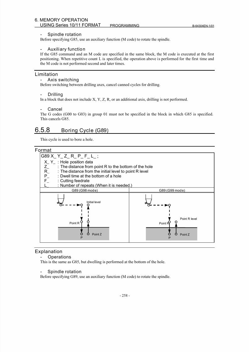
8/16/2019 Manual Operacion para FANUC
http://slidepdf.com/reader/full/manual-operacion-para-fanuc 276/435
PROGRAMMING B-64304EN-1/01
- 258 -
6. MEMORY OPERATIONUSING Series 10/11 FORMAT
- Spindle rotationBefore specifying G85, use an auxiliary function (M code) to rotate the spindle.
- Auxiliary function
If the G85 command and an M code are specified in the same block, the M code is executed at the first positioning. When repetitive count L is specified, the operation above is performed for the first time and
the M code is not performed second and later times.
Limitation- Axis switchingBefore switching between drilling axes, cancel canned cycles for drilling.
- DrillingIn a block that does not include X, Y, Z, R, or an additional axis, drilling is not performed.
- CancelThe G codes (G00 to G03) in group 01 must not be specified in the block in which G85 is specified.
This cancels G85.
6.5.8 Boring Cycle (G89)
This cycle is used to bore a hole.
Format
G89 X_ Y_ Z_ R_ P_ F_ L_ ;
X_ Y_ : Hole position data
Z_ : The distance from point R to the bottom of the holeR_ : The distance from the initial level to point R levelP_ : Dwell time at the bottom of a holeF_ : Cutting feedrateL_ : Number of repeats (When it is needed.)
G89 (G98 mode) G89 (G99 mode)
Point R
Point Z
Initial level
P
Point R
Point Z
Point R level
P
Explanation- OperationsThis is the same as G85, but dwelling is performed at the bottom of the hole.
- Spindle rotation
Before specifying G89, use an auxiliary function (M code) to rotate the spindle.
8/16/2019 Manual Operacion para FANUC
http://slidepdf.com/reader/full/manual-operacion-para-fanuc 277/435
B-64304EN-1/01 PROGRAMMING
- 259 -
6.MEMORY OPERATIONUSING Series 10/11 FORMAT
- Auxiliary functionIf the G89 command and an M code are specified in the same block, the M code is executed at the first
positioning. When repetitive count L is specified, the operation above is performed for the first time and
the M code is not performed second and later times.
Limitation- Axis switchingBefore switching between drilling axes, cancel canned cycles for drilling.
- DrillingIn a block that does not include X, Y, Z, R, or an additional axis, drilling is not performed.
- PP must be specified in a block in which drilling is instructed. Otherwise, data is not stored as modal data.
- CancelThe G codes (G00 to G03) in group 01 must not be specified in the block in which G89 is specified.
This cancels G89.
6.5.9 Canned Cycle for Dri lling Cancel (G80)
G80 cancels canned cycle for drilling.
FormatG80 ;
ExplanationCanned cycle for drilling is canceled to perform normal operation. Point R and point Z are cleared.
Other drilling data is also canceled (cleared).
6.5.10 Precautions to be Taken by Operator
- Reset and emergency stopEven when the controller is stopped by resetting or emergency stop in the course of drilling cycle, the
drilling mode and drilling data are saved ; with this mind, therefore, restart operation.
- Single blockWhen drilling cycle is performed with a single block, the operation stops at the end points of operations 1,
2, 6 in Fig. 6.5 (a).
Consequently, it follows that operation is started up 3 times to drill one hole. The operation stops at the
end points of operations 1, 2 with the feed hold lamp ON. If there is a remaining repetitive count at the
end of operation 6, the operation is stopped by feed hold. If there is no remaining repetitive count, the
operation is stopped in the single block stop state.
- Feed holdWhen "Feed Hold" is applied between operations 3 and 5 by G84/G88, the feed hold lamp lights up
immediately if the feed hold is applied again to operation 6.
- OverrideDuring operation with G84 and G88, the feedrate override is 100%.
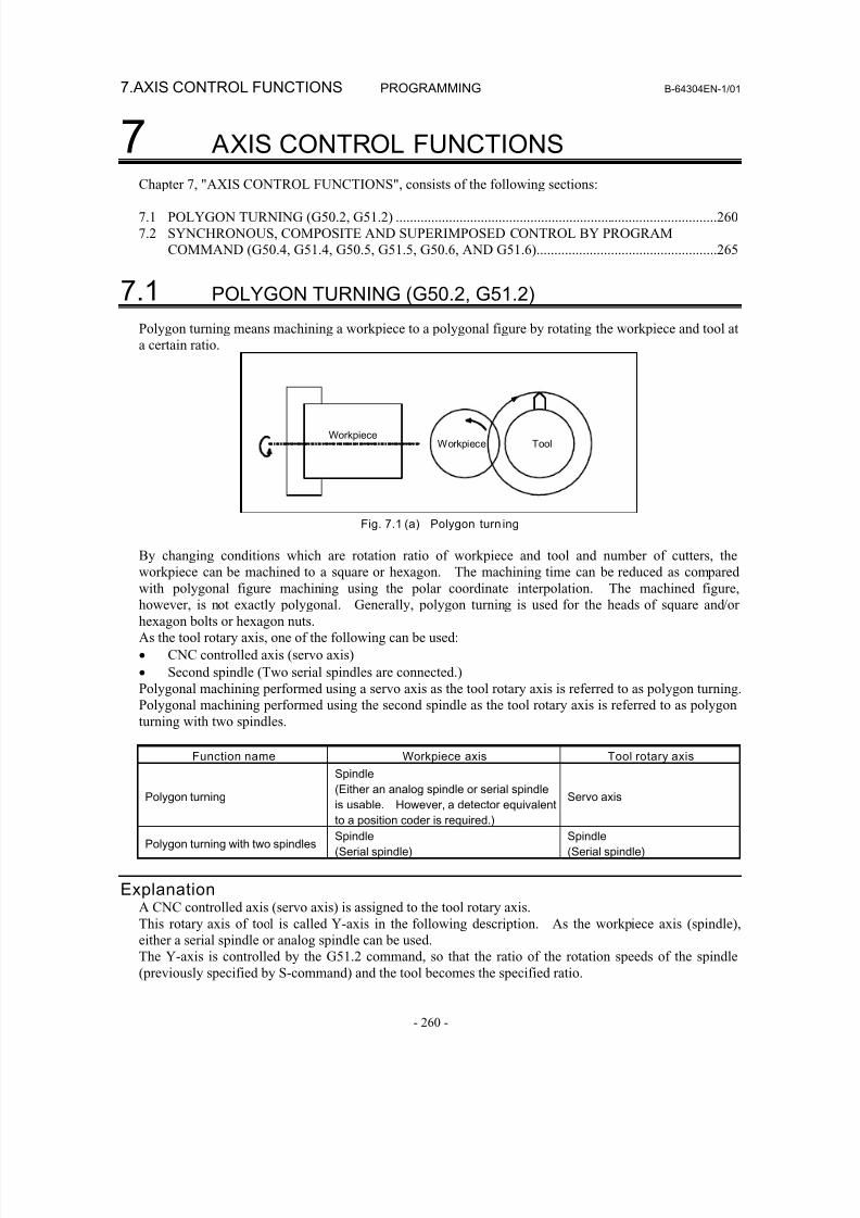
8/16/2019 Manual Operacion para FANUC
http://slidepdf.com/reader/full/manual-operacion-para-fanuc 278/435
7.AXIS CONTROL FUNCTIONS PROGRAMMING B-64304EN-1/01
- 260 -
7 AXIS CONTROL FUNCTIONS
Chapter 7, "AXIS CONTROL FUNCTIONS", consists of the following sections:
7.1 POLYGON TURNING (G50.2, G51.2) ...........................................................................................260
7.2 SYNCHRONOUS, COMPOSITE AND SUPERIMPOSED CONTROL BY PROGRAM
COMMAND (G50.4, G51.4, G50.5, G51.5, G50.6, AND G51.6)...................................................265
7.1 POLYGON TURNING (G50.2, G51.2)
Polygon turning means machining a workpiece to a polygonal figure by rotating the workpiece and tool at
a certain ratio.
WorkpieceWorkpiece Tool
Fig. 7.1 (a) Polygon turn ing
By changing conditions which are rotation ratio of workpiece and tool and number of cutters, the
workpiece can be machined to a square or hexagon. The machining time can be reduced as comparedwith polygonal figure machining using the polar coordinate interpolation. The machined figure,
however, is not exactly polygonal. Generally, polygon turning is used for the heads of square and/or
hexagon bolts or hexagon nuts.
As the tool rotary axis, one of the following can be used:
• CNC controlled axis (servo axis)
• Second spindle (Two serial spindles are connected.)
Polygonal machining performed using a servo axis as the tool rotary axis is referred to as polygon turning.
Polygonal machining performed using the second spindle as the tool rotary axis is referred to as polygon
turning with two spindles.
Function name Workpiece axis Tool rotary axis
Polygon turning
Spindle
(Either an analog spindle or serial spindle
is usable. However, a detector equivalent
to a position coder is required.)
Servo axis
Polygon turning with two spindlesSpindle
(Serial spindle)
Spindle
(Serial spindle)
ExplanationA CNC controlled axis (servo axis) is assigned to the tool rotary axis.
This rotary axis of tool is called Y-axis in the following description. As the workpiece axis (spindle),
either a serial spindle or analog spindle can be used.
The Y-axis is controlled by the G51.2 command, so that the ratio of the rotation speeds of the spindle(previously specified by S-command) and the tool becomes the specified ratio.
8/16/2019 Manual Operacion para FANUC
http://slidepdf.com/reader/full/manual-operacion-para-fanuc 279/435
B-64304EN-1/01 PROGRAMMING 7.AXIS CONTROL FUNCTIONS
- 261 -
When simultaneous start is specified by G51.2, the one-rotation signal sent from the position codes set on
the spindle is detected. After one-rotation signal detection, the Y-axis is controlled using the rotation
ratio of the spindle and Y-axis specified by P and Q. So, a position coder needs to be attached to the
spindle. This control will be maintained until the polygon turning cancel command is executed (G50.2).
Polygon turning is cancelled by any of the following in addition to the G50.2 command:
(1) Power off
(2) Emergency stop
(3) Servo alarm
(4) Reset (external reset signal ERS, reset/rewind signal RRW, and RESET key on the MDI panel)
(5) Occurrence of alarms PS0217 to PS0221, PS0314, and PS05018
NOTE1 Before polygon turning, reference position return operation on the Y-axis needs
to be specified to determine the rotation start position of the tool. Thisreference position return operation is performed by detecting a deceleration limitas in the case of manual reference position return operation. (By setting bit 7(PLZ) of parameter No. 7600, reference position return operation can beperformed without detecting a deceleration limit.)
2 The rotation direction on the Y-axis is determined by the sign of Q, and is notaffected by the rotation direction of the position coder.
3 Among the current position display of the Y axis, the display for the machinecoordinate value (MACHINE) changes from a range of 0 to the amount ofmovement per revolution as the Y axis moves. Absolute and relative coordinatevalues are not updated. So, when specifying an absolute programming for theY-axis after polygon turning mode cancellation, set a workpiece coordinatesystem after reference position return operation.
4 For the Y-axis engaged in polygon turning, jog feed and handle feed aredisabled.5 For the Y-axis not engaged in polygon turning, a move command can be
specified as in the case of other controlled axes.6 The Y-axis engaged in polygon turning is not counted in the number of
simultaneously controlled axes.7 One workpiece must be machined using a fixed spindle speed until the
workpiece is finished.8 Polygon turning with two spindles cannot be used at the same time.9 G50.2 is the G code for suppressing buffering.
8/16/2019 Manual Operacion para FANUC
http://slidepdf.com/reader/full/manual-operacion-para-fanuc 280/435
7.AXIS CONTROL FUNCTIONS PROGRAMMING B-64304EN-1/01
- 262 -
CAUTION1 During polygon turning, threading cannot be performed.2 For the Y-axis engaged in synchronous operation, the signals below are valid or
invalid:
Signals valid for the Y-axis• Machine lock
• Servo-off
Signals invalid for the Y-axis
• Feed hold
• Interlock
• Override
• Dry run
(At dry run time, however, the one-rotation signal is not awaited in a G51.2block.)
FormatG50.2 Polygon turning cancel
G51.2 P_ Q_ ; Start of polygon turning
P,Q: Rotation ratio of spindle and Y-axisSpecify range:P: Integer from 1 to 999Q: Integer from -999 to -1 or from 1 to 999
When Q is a positive value, Y-axis makes positive rotation.When Q is a negative value, Y-axis makes negative rotation.
NOTESpecify G50.2 and G51.2 in a single block.
ExampleG00 X100. 0 Z20.0 S1000.0 M03 ; (Workpiece rotation speed 1000 (min
-1))
G51.2 P1 Q2 ; (Tool rotation start (tool rotation speed 2000 (min-1
))
G01 X80.0 F10.0 ; (X-axis in-feed)
G04 X2.0 ; (Waiting 2 seconds)
G00 X100.0 ; (X-axis escape)
G50.2 ; (Tool rotation stop)
M05 S0 ; (Spindle stop )
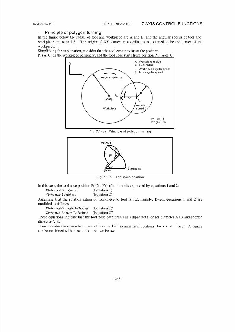
8/16/2019 Manual Operacion para FANUC
http://slidepdf.com/reader/full/manual-operacion-para-fanuc 281/435
B-64304EN-1/01 PROGRAMMING 7.AXIS CONTROL FUNCTIONS
- 263 -
- Principle of polygon turningIn the figure below the radius of tool and workpiece are A and B, and the angular speeds of tool and
workpiece are α and β. The origin of XY Cartesian coordinates is assumed to be the center of the
workpiece.
Simplifying the explanation, consider that the tool center exists at the positionPo (A, 0) on the workpiece periphery, and the tool nose starts from position P to (A-B, 0).
Y
X
A
(0,0)
Pto
Po
B
Angular speed α
A : Workpiece radiusB : Rool radius
Angularspeed βWorkpiece
Tool
α : Workpiece angular speedβ : Tool angular speed
Po (A, 0)Pto (A-B, 0)
Fig. 7.1 (b) Principle of polygon turning
(0, 0)
αt
βt A
P
Start point
B
Pt (Xt, Yt)
Fig. 7.1 (c) Tool nose posi tion
In this case, the tool nose position Pt (Xt, Yt) after time t is expressed by equations 1 and 2:
Xt= Acosα t-Bcos( β -α )t (Equation 1)
Yt= Asinα t+Bsin( β -α )t (Equation 2)
Assuming that the rotation ration of workpiece to tool is 1:2, namely, β=2α, equations 1 and 2 are
modified as follows:
Xt= Acosα t-Bcosα t=( A-B)cosα t (Equation 1)'Xt= Asinα t+Bsinα t=( A+B)sinα t (Equation 2)'
These equations indicate that the tool nose path draws an ellipse with longer diameter A+B and shorter
diameter A-B.
Then consider the case when one tool is set at 180° symmetrical positions, for a total of two. A square
can be machined with these tools as shown below.
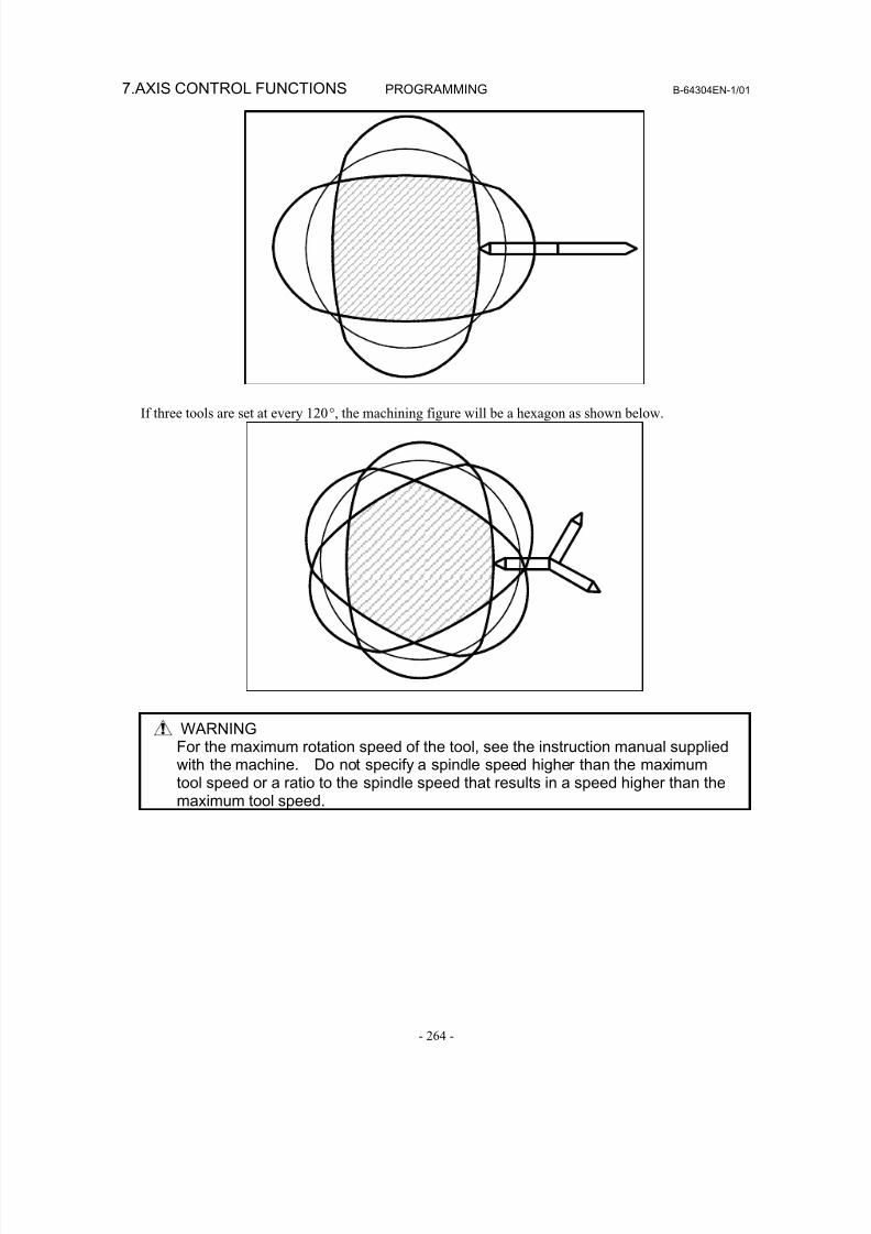
8/16/2019 Manual Operacion para FANUC
http://slidepdf.com/reader/full/manual-operacion-para-fanuc 282/435
7.AXIS CONTROL FUNCTIONS PROGRAMMING B-64304EN-1/01
- 264 -
If three tools are set at every 120°, the machining figure will be a hexagon as shown below.
WARNINGFor the maximum rotation speed of the tool, see the instruction manual suppliedwith the machine. Do not specify a spindle speed higher than the maximumtool speed or a ratio to the spindle speed that results in a speed higher than themaximum tool speed.
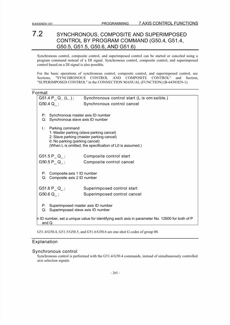
8/16/2019 Manual Operacion para FANUC
http://slidepdf.com/reader/full/manual-operacion-para-fanuc 283/435
B-64304EN-1/01 PROGRAMMING 7.AXIS CONTROL FUNCTIONS
- 265 -
7.2 SYNCHRONOUS, COMPOSITE AND SUPERIMPOSEDCONTROL BY PROGRAM COMMAND (G50.4, G51.4,
G50.5, G51.5, G50.6, AND G51.6)
Synchronous control, composite control, and superimposed control can be started or canceled using a
program command instead of a DI signal. Synchronous control, composite control, and superimposed
control based on a DI signal is also possible.
For the basic operations of synchronous control, composite control, and superimposed control, see
Sections, "SYNCHRONOUS CONTROL AND COMPOSITE CONTROL" and Section,
"SUPERIMPOSED CONTROL" in the CONNECTION MANUAL (FUNCTION) (B-64303EN-1).
FormatG51.4 P_ Q_ (L_) ; Synchronous control start (L is omissible.)
G50.4 Q_ ; Synchronous control cancel
P: Synchronous master axis ID numberQ: Synchronous slave axis ID number
L: Parking command1: Master parking (slave parking cancel)2: Slave parking (master parking cancel)0: No parking (parking cancel)(When L is omitted, the specification of L0 is assumed.)
G51.5 P_ Q_ ; Composi te control start
G50.5 P_ Q_ ; Composi te control cancel
P: Composite axis 1 ID numberQ: Composite axis 2 ID number
G51.6 P_ Q_ ; Superimposed control start
G50.6 Q_ ; Superimposed control cancel
P: Superimposed master axis ID numberQ: Superimposed slave axis ID number
n ID number, set a unique value for identifying each axis in parameter No. 12600 for both of Pand Q.
G51.4/G50.4, G51.5/G50.5, and G51.6/G50.6 are one-shot G codes of group 00.
Explanation
Synchronous controlSynchronous control is performed with the G51.4/G50.4 commands, instead of simultaneously controlledaxis selection signals.
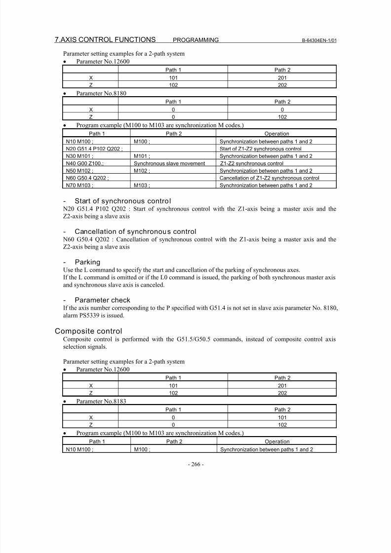
8/16/2019 Manual Operacion para FANUC
http://slidepdf.com/reader/full/manual-operacion-para-fanuc 284/435
7.AXIS CONTROL FUNCTIONS PROGRAMMING B-64304EN-1/01
- 266 -
Parameter setting examples for a 2-path system
• Parameter No.12600
Path 1 Path 2
X 101 201
Z 102 202• Parameter No.8180
Path 1 Path 2
X 0 0
Z 0 102
• Program example (M100 to M103 are synchronization M codes.)
Path 1 Path 2 Operation
N10 M100 ; M100 ; Synchronization between paths 1 and 2
N20 G51.4 P102 Q202 ; Start of Z1-Z2 synchronous control
N30 M101 ; M101 ; Synchronization between paths 1 and 2
N40 G00 Z100.; Synchronous slave movement Z1-Z2 synchronous control
N50 M102 ; M102 ; Synchronization between paths 1 and 2
N60 G50.4 Q202 ; Cancellation of Z1-Z2 synchronous control
N70 M103 ; M103 ; Synchronization between paths 1 and 2
- Start of synchronous contro l N20 G51.4 P102 Q202 : Start of synchronous control with the Z1-axis being a master axis and the
Z2-axis being a slave axis
- Cancellation of synchronous control N60 G50.4 Q202 : Cancellation of synchronous control with the Z1-axis being a master axis and the
Z2-axis being a slave axis
- ParkingUse the L command to specify the start and cancellation of the parking of synchronous axes.
If the L command is omitted or if the L0 command is issued, the parking of both synchronous master axis
and synchronous slave axis is canceled.
- Parameter checkIf the axis number corresponding to the P specified with G51.4 is not set in slave axis parameter No. 8180,
alarm PS5339 is issued.
Composite controlComposite control is performed with the G51.5/G50.5 commands, instead of composite control axis
selection signals.
Parameter setting examples for a 2-path system
• Parameter No.12600
Path 1 Path 2
X 101 201
Z 102 202
• Parameter No.8183
Path 1 Path 2
X 0 101
Z 0 102
• Program example (M100 to M103 are synchronization M codes.)Path 1 Path 2 Operation
N10 M100 ; M100 ; Synchronization between paths 1 and 2
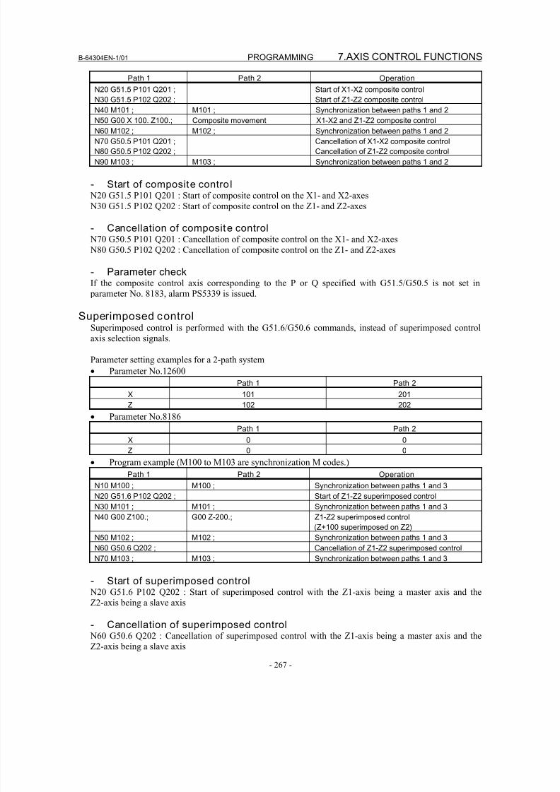
8/16/2019 Manual Operacion para FANUC
http://slidepdf.com/reader/full/manual-operacion-para-fanuc 285/435
B-64304EN-1/01 PROGRAMMING 7.AXIS CONTROL FUNCTIONS
- 267 -
Path 1 Path 2 Operation
N20 G51.5 P101 Q201 ;
N30 G51.5 P102 Q202 ;
Start of X1-X2 composite control
Start of Z1-Z2 composite control
N40 M101 ; M101 ; Synchronization between paths 1 and 2
N50 G00 X 100. Z100.; Composite movement X1-X2 and Z1-Z2 composite controlN60 M102 ; M102 ; Synchronization between paths 1 and 2
N70 G50.5 P101 Q201 ;
N80 G50.5 P102 Q202 ;
Cancellation of X1-X2 composite control
Cancellation of Z1-Z2 composite control
N90 M103 ; M103 ; Synchronization between paths 1 and 2
- Start of composite contro l N20 G51.5 P101 Q201 : Start of composite control on the X1- and X2-axes
N30 G51.5 P102 Q202 : Start of composite control on the Z1- and Z2-axes
- Cancellation of composite control N70 G50.5 P101 Q201 : Cancellation of composite control on the X1- and X2-axes
N80 G50.5 P102 Q202 : Cancellation of composite control on the Z1- and Z2-axes
- Parameter checkIf the composite control axis corresponding to the P or Q specified with G51.5/G50.5 is not set in
parameter No. 8183, alarm PS5339 is issued.
Superimposed controlSuperimposed control is performed with the G51.6/G50.6 commands, instead of superimposed control
axis selection signals.
Parameter setting examples for a 2-path system
• Parameter No.12600Path 1 Path 2
X 101 201
Z 102 202
• Parameter No.8186
Path 1 Path 2
X 0 0
Z 0 0
• Program example (M100 to M103 are synchronization M codes.)
Path 1 Path 2 Operation
N10 M100 ; M100 ; Synchronization between paths 1 and 3
N20 G51.6 P102 Q202 ; Start of Z1-Z2 superimposed controlN30 M101 ; M101 ; Synchronization between paths 1 and 3
N40 G00 Z100.; G00 Z-200.; Z1-Z2 superimposed control
(Z+100 superimposed on Z2)
N50 M102 ; M102 ; Synchronization between paths 1 and 3
N60 G50.6 Q202 ; Cancellation of Z1-Z2 superimposed control
N70 M103 ; M103 ; Synchronization between paths 1 and 3
- Start of superimposed control N20 G51.6 P102 Q202 : Start of superimposed control with the Z1-axis being a master axis and the
Z2-axis being a slave axis
- Cancellation of superimposed control N60 G50.6 Q202 : Cancellation of superimposed control with the Z1-axis being a master axis and the
Z2-axis being a slave axis
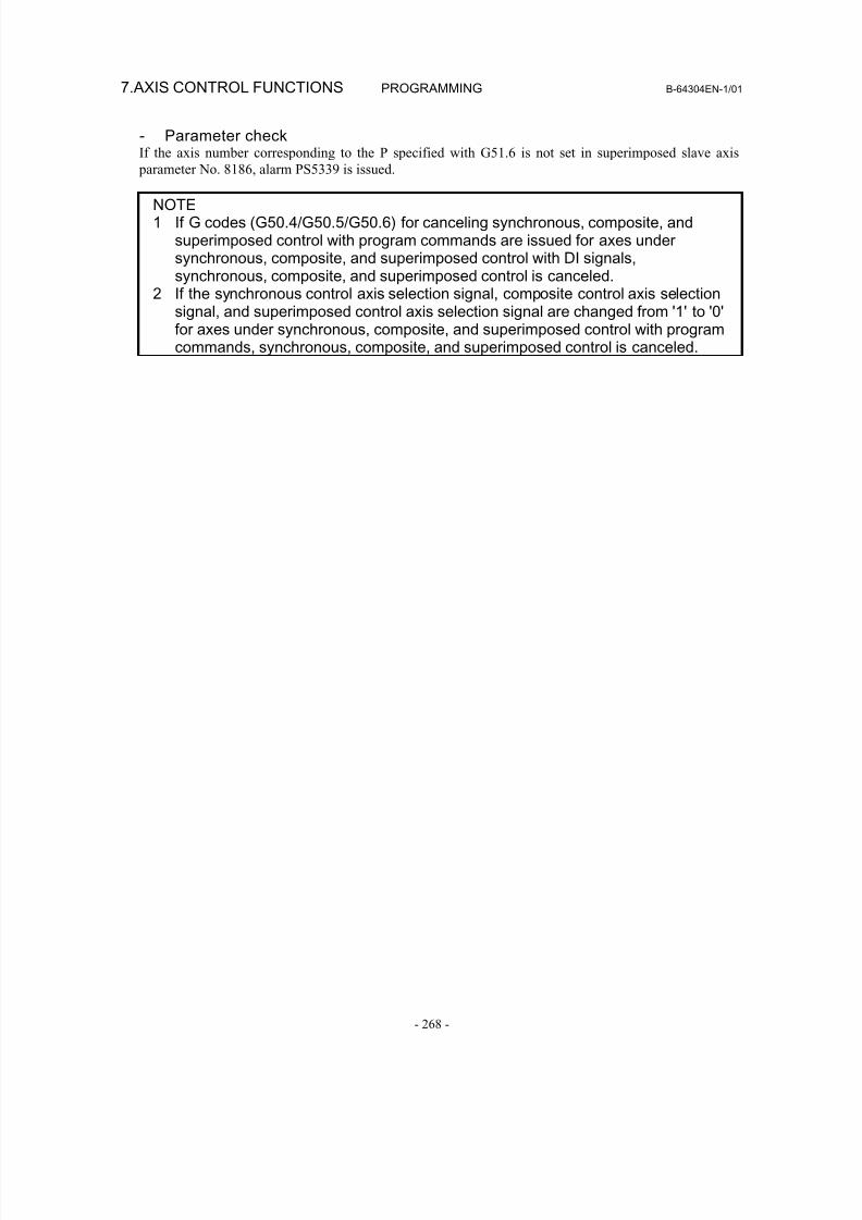
8/16/2019 Manual Operacion para FANUC
http://slidepdf.com/reader/full/manual-operacion-para-fanuc 286/435
7.AXIS CONTROL FUNCTIONS PROGRAMMING B-64304EN-1/01
- 268 -
- Parameter checkIf the axis number corresponding to the P specified with G51.6 is not set in superimposed slave axis
parameter No. 8186, alarm PS5339 is issued.
NOTE1 If G codes (G50.4/G50.5/G50.6) for canceling synchronous, composite, and
superimposed control with program commands are issued for axes undersynchronous, composite, and superimposed control with DI signals,synchronous, composite, and superimposed control is canceled.
2 If the synchronous control axis selection signal, composite control axis selectionsignal, and superimposed control axis selection signal are changed from '1' to '0'for axes under synchronous, composite, and superimposed control with programcommands, synchronous, composite, and superimposed control is canceled.
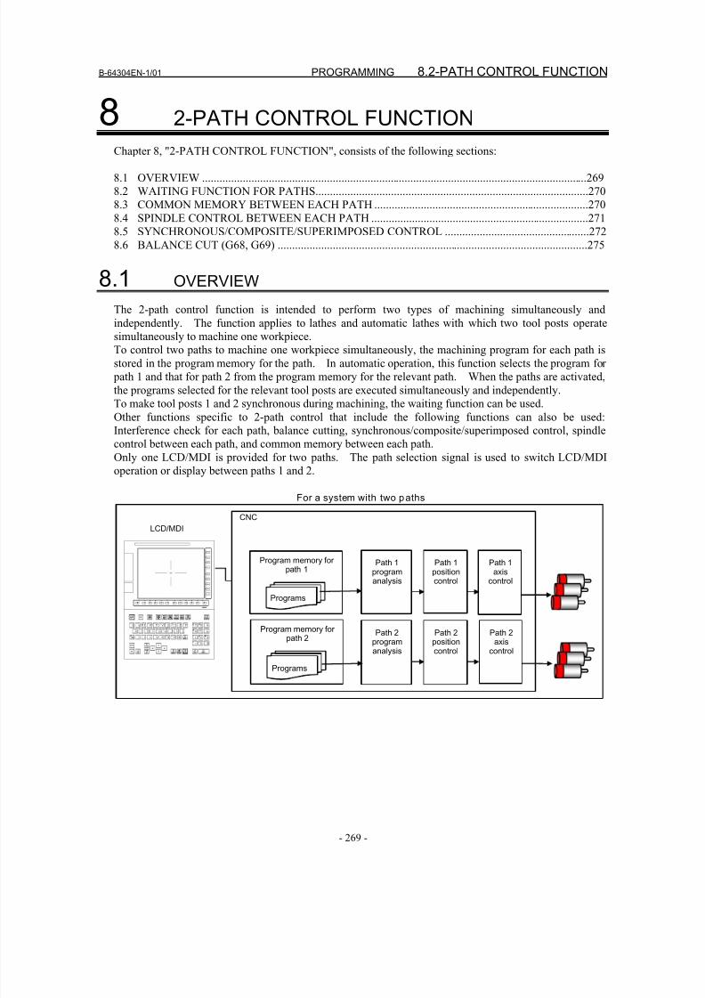
8/16/2019 Manual Operacion para FANUC
http://slidepdf.com/reader/full/manual-operacion-para-fanuc 287/435
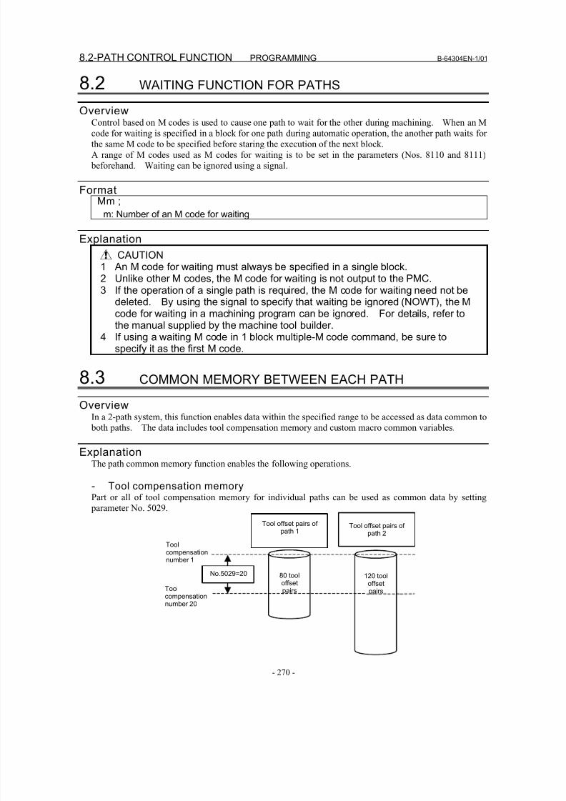
8/16/2019 Manual Operacion para FANUC
http://slidepdf.com/reader/full/manual-operacion-para-fanuc 288/435
8.2-PATH CONTROL FUNCTION PROGRAMMING B-64304EN-1/01
- 270 -
8.2 WAITING FUNCTION FOR PATHS
Overview
Control based on M codes is used to cause one path to wait for the other during machining. When an Mcode for waiting is specified in a block for one path during automatic operation, the another path waits for
the same M code to be specified before staring the execution of the next block.
A range of M codes used as M codes for waiting is to be set in the parameters (Nos. 8110 and 8111)
beforehand. Waiting can be ignored using a signal.
FormatMm ;
m: Number of an M code for waiting
Explanation
CAUTION1 An M code for waiting must always be specified in a single block.2 Unlike other M codes, the M code for waiting is not output to the PMC.3 If the operation of a single path is required, the M code for waiting need not be
deleted. By using the signal to specify that waiting be ignored (NOWT), the Mcode for waiting in a machining program can be ignored. For details, refer tothe manual supplied by the machine tool builder.
4 If using a waiting M code in 1 block multiple-M code command, be sure tospecify it as the first M code.
8.3 COMMON MEMORY BETWEEN EACH PATH
OverviewIn a 2-path system, this function enables data within the specified range to be accessed as data common to
both paths. The data includes tool compensation memory and custom macro common variables.
ExplanationThe path common memory function enables the following operations.
- Tool compensation memoryPart or all of tool compensation memory for individual paths can be used as common data by setting
parameter No. 5029.
Toolcompensationnumber 20
Toolcompensationnumber 1
120 tooloffsetpairs
80 tooloffsetpairs
Tool offset pairs ofpath 2
No.5029=20
Tool offset pairs ofpath 1
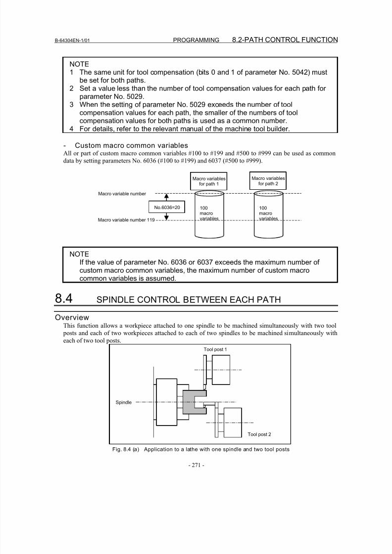
8/16/2019 Manual Operacion para FANUC
http://slidepdf.com/reader/full/manual-operacion-para-fanuc 289/435
B-64304EN-1/01 PROGRAMMING 8.2-PATH CONTROL FUNCTION
- 271 -
NOTE1 The same unit for tool compensation (bits 0 and 1 of parameter No. 5042) must
be set for both paths.
2 Set a value less than the number of tool compensation values for each path forparameter No. 5029.
3 When the setting of parameter No. 5029 exceeds the number of toolcompensation values for each path, the smaller of the numbers of toolcompensation values for both paths is used as a common number.
4 For details, refer to the relevant manual of the machine tool builder.
- Custom macro common variablesAll or part of custom macro common variables #100 to #199 and #500 to #999 can be used as common
data by setting parameters No. 6036 (#100 to #199) and 6037 (#500 to #999).
100macrovariables
100macrovariablesMacro variable number 119
Macro variable number
Macro variablesfor path 1
No.6036=20
Macro variablesfor path 2
NOTE
If the value of parameter No. 6036 or 6037 exceeds the maximum number ofcustom macro common variables, the maximum number of custom macrocommon variables is assumed.
8.4 SPINDLE CONTROL BETWEEN EACH PATH
OverviewThis function allows a workpiece attached to one spindle to be machined simultaneously with two tool
posts and each of two workpieces attached to each of two spindles to be machined simultaneously with
each of two tool posts.
Spindle
Tool post 1
Tool post 2
Fig. 8.4 (a) Application to a lathe with one spindle and two tool posts
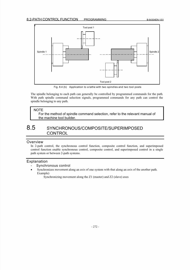
8/16/2019 Manual Operacion para FANUC
http://slidepdf.com/reader/full/manual-operacion-para-fanuc 290/435
8.2-PATH CONTROL FUNCTION PROGRAMMING B-64304EN-1/01
- 272 -
¥
Tool post 2
Spindle 1
Tool post 1
Spindle 2
Fig. 8.4 (b) Application to a lathe with two spind les and two tool posts
The spindle belonging to each path can generally be controlled by programmed commands for the path.
With path spindle command selection signals, programmed commands for any path can control the
spindle belonging to any path.
NOTEFor the method of spindle command selection, refer to the relevant manual ofthe machine tool builder.
8.5 SYNCHRONOUS/COMPOSITE/SUPERIMPOSEDCONTROL
OverviewIn 2-path control, the synchronous control function, composite control function, and superimposed
control function enable synchronous control, composite control, and superimposed control in a single
path system or between 2-path systems.
Explanation- Synchronous control
• Synchronizes movement along an axis of one system with that along an axis of the another path.Example)
Synchronizing movement along the Z1 (master) and Z2 (slave) axes
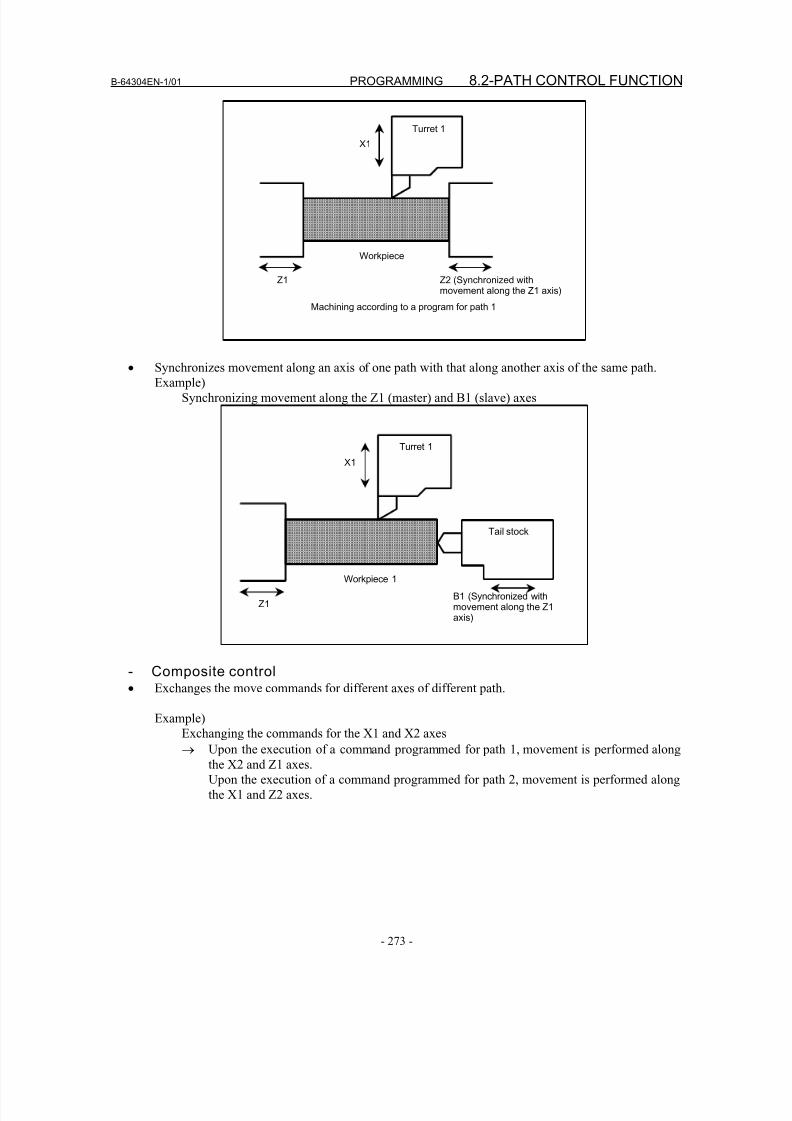
8/16/2019 Manual Operacion para FANUC
http://slidepdf.com/reader/full/manual-operacion-para-fanuc 291/435
B-64304EN-1/01 PROGRAMMING 8.2-PATH CONTROL FUNCTION
- 273 -
Workpiece
Z2 (Synchronized withmovement along the Z1 axis)
Z1
Turret 1
X1
Machining according to a program for path 1
• Synchronizes movement along an axis of one path with that along another axis of the same path.
Example)
Synchronizing movement along the Z1 (master) and B1 (slave) axes
B1 (Synchronized withmovement along the Z1axis)
Workpiece 1
Z1
Turret 1
X1
Tail stock
- Composite control• Exchanges the move commands for different axes of different path.
Example)
Exchanging the commands for the X1 and X2 axes
→ Upon the execution of a command programmed for path 1, movement is performed along
the X2 and Z1 axes.
Upon the execution of a command programmed for path 2, movement is performed along
the X1 and Z2 axes.

8/16/2019 Manual Operacion para FANUC
http://slidepdf.com/reader/full/manual-operacion-para-fanuc 292/435
8.2-PATH CONTROL FUNCTION PROGRAMMING B-64304EN-1/01
- 274 -
Machining according to a programfor path 1
Machining according toa program for path 2
Workpiece 1
Turret 1
Workpiece 2
Turret 1
Z1
X2
Z2
X1
- Superimposed control• Provides a move command of an axis for a different axis in another path.
Example)
Providing the Z2 (slave) axis with a move command specified for the Z1 (master) axis
Machining according to a program
for path 2
Workpiece 1
Turret 1
Turret 2
Z1 X2
Z2
X1Machining according toa program for path 1
NOTEThe method used to specify synchronous, composite, or superimposed controlvaries with the machine tool builder. For details, refer to the manual suppliedby the machine tool builder.
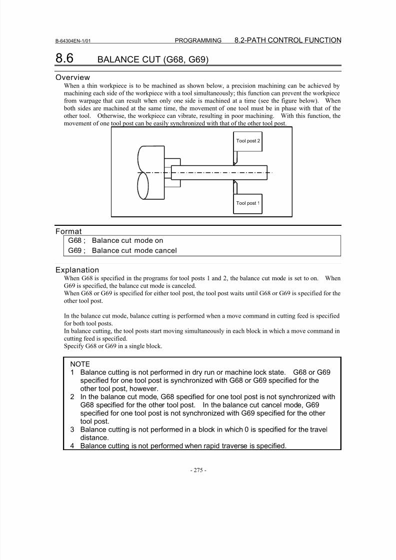
8/16/2019 Manual Operacion para FANUC
http://slidepdf.com/reader/full/manual-operacion-para-fanuc 293/435
B-64304EN-1/01 PROGRAMMING 8.2-PATH CONTROL FUNCTION
- 275 -
8.6 BALANCE CUT (G68, G69)
Overview
When a thin workpiece is to be machined as shown below, a precision machining can be achieved bymachining each side of the workpiece with a tool simultaneously; this function can prevent the workpiece
from warpage that can result when only one side is machined at a time (see the figure below). When
both sides are machined at the same time, the movement of one tool must be in phase with that of the
other tool. Otherwise, the workpiece can vibrate, resulting in poor machining. With this function, the
movement of one tool post can be easily synchronized with that of the other tool post.
Tool post 1
Tool post 2
FormatG68 ; Balance cut mode on
G69 ; Balance cut mode cancel
ExplanationWhen G68 is specified in the programs for tool posts 1 and 2, the balance cut mode is set to on. When
G69 is specified, the balance cut mode is canceled.
When G68 or G69 is specified for either tool post, the tool post waits until G68 or G69 is specified for the
other tool post.
In the balance cut mode, balance cutting is performed when a move command in cutting feed is specified
for both tool posts.
In balance cutting, the tool posts start moving simultaneously in each block in which a move command in
cutting feed is specified.
Specify G68 or G69 in a single block.
NOTE1 Balance cutting is not performed in dry run or machine lock state. G68 or G69
specified for one tool post is synchronized with G68 or G69 specified for theother tool post, however.
2 In the balance cut mode, G68 specified for one tool post is not synchronized withG68 specified for the other tool post. In the balance cut cancel mode, G69specified for one tool post is not synchronized with G69 specified for the othertool post.
3 Balance cutting is not performed in a block in which 0 is specified for the travel
distance.4 Balance cutting is not performed when rapid traverse is specified.
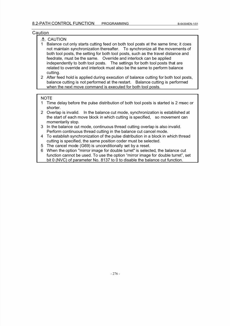
8/16/2019 Manual Operacion para FANUC
http://slidepdf.com/reader/full/manual-operacion-para-fanuc 294/435
8.2-PATH CONTROL FUNCTION PROGRAMMING B-64304EN-1/01
- 276 -
Caution
CAUTION1 Balance cut only starts cutting feed on both tool posts at the same time; it does
not maintain synchronization thereafter. To synchronize all the movements ofboth tool posts, the setting for both tool posts, such as the travel distance andfeedrate, must be the same. Override and interlock can be appliedindependently to both tool posts. The settings for both tool posts that arerelated to override and interlock must also be the same to perform balancecutting.
2 After feed hold is applied during execution of balance cutting for both tool posts,balance cutting is not performed at the restart. Balance cutting is performedwhen the next move command is executed for both tool posts.
NOTE
1 Time delay before the pulse distribution of both tool posts is started is 2 msec orshorter.
2 Overlap is invalid. In the balance cut mode, synchronization is established atthe start of each move block in which cutting is specified, so movement canmomentarily stop.
3 In the balance cut mode, continuous thread cutting overlap is also invalid.Perform continuous thread cutting in the balance cut cancel mode.
4 To establish synchronization of the pulse distribution in a block in which threadcutting is specified, the same position coder must be selected.
5 The cancel mode (G69) is unconditionally set by a reset.6 When the option "mirror image for double turret" is selected, the balance cut
function cannot be used. To use the option “mirror image for double turret”, setbit 0 (NVC) of parameter No. 8137 to 0 to disable the balance cut function.

8/16/2019 Manual Operacion para FANUC
http://slidepdf.com/reader/full/manual-operacion-para-fanuc 295/435
III. OPERATION

8/16/2019 Manual Operacion para FANUC
http://slidepdf.com/reader/full/manual-operacion-para-fanuc 296/435
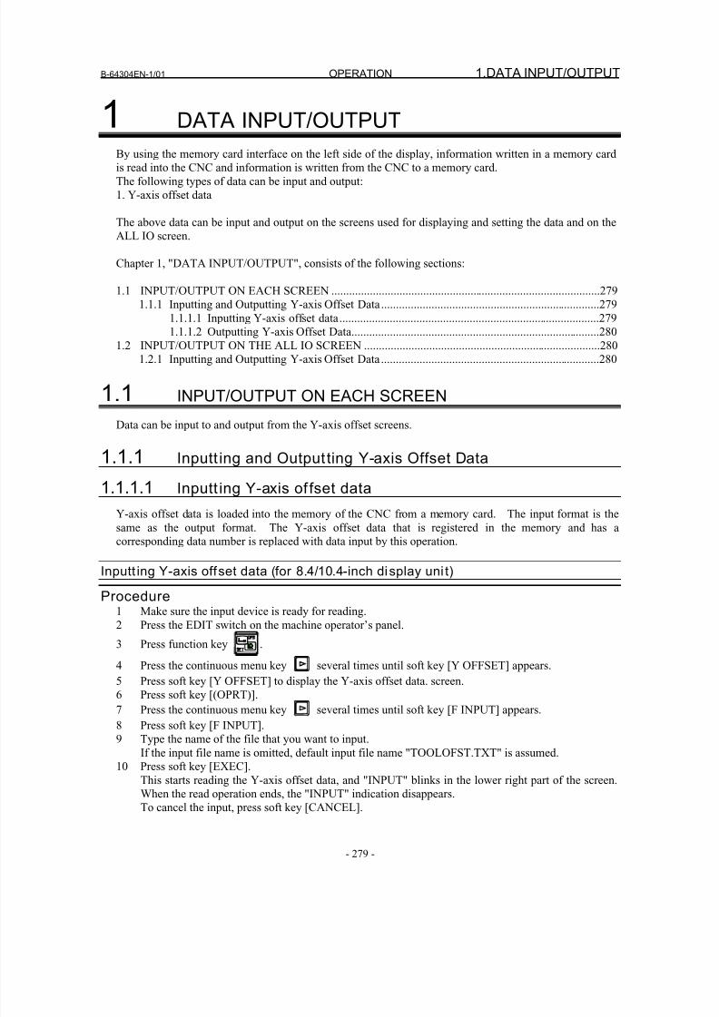
8/16/2019 Manual Operacion para FANUC
http://slidepdf.com/reader/full/manual-operacion-para-fanuc 297/435
B-64304EN-1/01 OPERATION 1.DATA INPUT/OUTPUT
- 279 -
1 DATA INPUT/OUTPUT
By using the memory card interface on the left side of the display, information written in a memory cardis read into the CNC and information is written from the CNC to a memory card.
The following types of data can be input and output:
1. Y-axis offset data
The above data can be input and output on the screens used for displaying and setting the data and on the
ALL IO screen.
Chapter 1, "DATA INPUT/OUTPUT", consists of the following sections:
1.1 INPUT/OUTPUT ON EACH SCREEN ...........................................................................................279
1.1.1 Inputting and Outputting Y-axis Offset Data..........................................................................279
1.1.1.1 Inputting Y-axis offset data........................................................................................2791.1.1.2 Outputting Y-axis Offset Data....................................................................................280
1.2 INPUT/OUTPUT ON THE ALL IO SCREEN ................................................................................280
1.2.1 Inputting and Outputting Y-axis Offset Data..........................................................................280
1.1 INPUT/OUTPUT ON EACH SCREEN
Data can be input to and output from the Y-axis offset screens.
1.1.1 Inputt ing and Output ting Y-axis Offset Data
1.1.1.1 Inputt ing Y-axis of fset data
Y-axis offset data is loaded into the memory of the CNC from a memory card. The input format is the
same as the output format. The Y-axis offset data that is registered in the memory and has a
corresponding data number is replaced with data input by this operation.
Inputt ing Y-axis offset data (for 8.4/10.4-inch display uni t)
Procedure1 Make sure the input device is ready for reading.
2 Press the EDIT switch on the machine operator’s panel.
3 Press function key .
4 Press the continuous menu key several times until soft key [Y OFFSET] appears.
5 Press soft key [Y OFFSET] to display the Y-axis offset data. screen.
6 Press soft key [(OPRT)].
7 Press the continuous menu key several times until soft key [F INPUT] appears.
8 Press soft key [F INPUT].
9 Type the name of the file that you want to input.
If the input file name is omitted, default input file name "TOOLOFST.TXT" is assumed.
10 Press soft key [EXEC].
This starts reading the Y-axis offset data, and "INPUT" blinks in the lower right part of the screen.
When the read operation ends, the "INPUT" indication disappears.To cancel the input, press soft key [CANCEL].
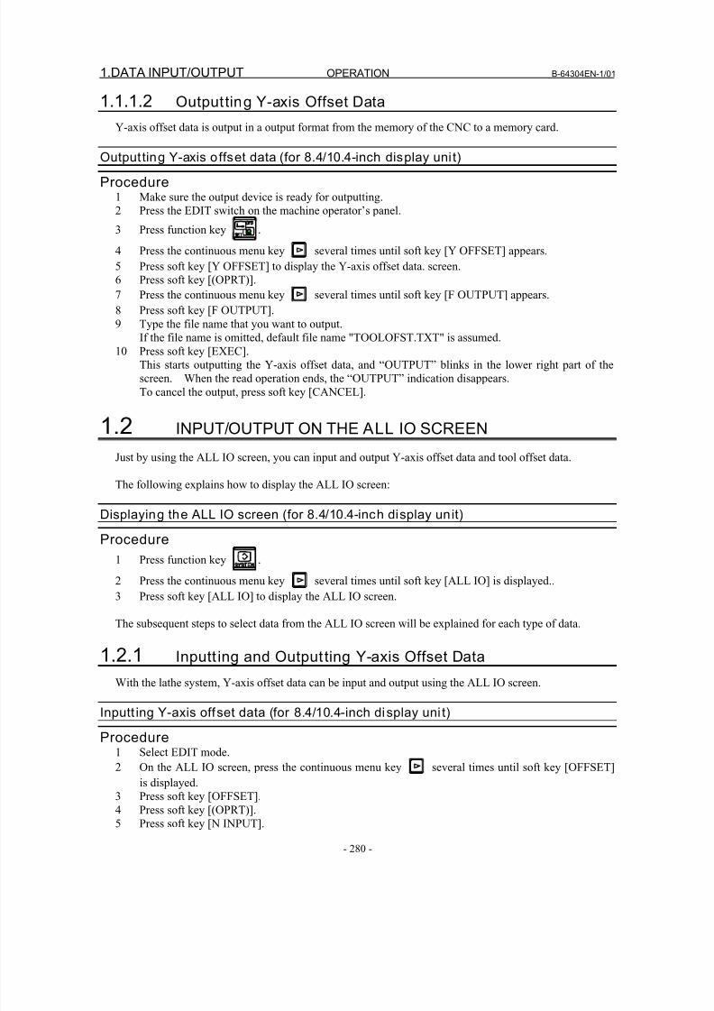
8/16/2019 Manual Operacion para FANUC
http://slidepdf.com/reader/full/manual-operacion-para-fanuc 298/435
1.DATA INPUT/OUTPUT OPERATION B-64304EN-1/01
- 280 -
1.1.1.2 Outputting Y-axis Offset Data
Y-axis offset data is output in a output format from the memory of the CNC to a memory card.
Outputting Y-axis o ffset data (for 8.4/10.4-inch display unit)
Procedure1 Make sure the output device is ready for outputting.
2 Press the EDIT switch on the machine operator’s panel.
3 Press function key .
4 Press the continuous menu key several times until soft key [Y OFFSET] appears.
5 Press soft key [Y OFFSET] to display the Y-axis offset data. screen.
6 Press soft key [(OPRT)].
7 Press the continuous menu key several times until soft key [F OUTPUT] appears.
8 Press soft key [F OUTPUT].
9 Type the file name that you want to output.
If the file name is omitted, default file name "TOOLOFST.TXT" is assumed.
10 Press soft key [EXEC].
This starts outputting the Y-axis offset data, and “OUTPUT” blinks in the lower right part of the
screen. When the read operation ends, the “OUTPUT” indication disappears.
To cancel the output, press soft key [CANCEL].
1.2 INPUT/OUTPUT ON THE ALL IO SCREEN
Just by using the ALL IO screen, you can input and output Y-axis offset data and tool offset data.
The following explains how to display the ALL IO screen:
Displaying the ALL IO screen (for 8.4/10.4-inch display unit)
Procedure
1 Press function key .
2 Press the continuous menu key several times until soft key [ALL IO] is displayed..
3 Press soft key [ALL IO] to display the ALL IO screen.
The subsequent steps to select data from the ALL IO screen will be explained for each type of data.
1.2.1 Inputt ing and Output ting Y-axis Offset Data
With the lathe system, Y-axis offset data can be input and output using the ALL IO screen.
Inputt ing Y-axis offset data (for 8.4/10.4-inch display uni t)
Procedure1 Select EDIT mode.
2 On the ALL IO screen, press the continuous menu key several times until soft key [OFFSET]
is displayed.
3 Press soft key [OFFSET].4 Press soft key [(OPRT)].
5 Press soft key [N INPUT].
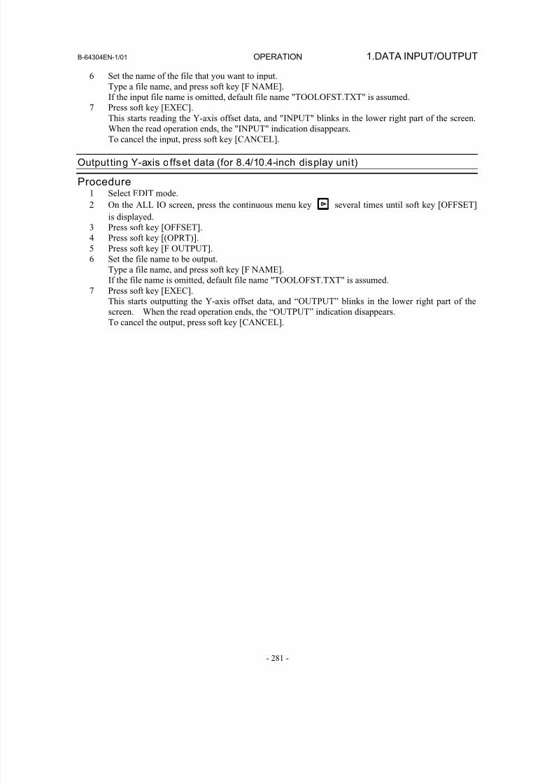
8/16/2019 Manual Operacion para FANUC
http://slidepdf.com/reader/full/manual-operacion-para-fanuc 299/435
B-64304EN-1/01 OPERATION 1.DATA INPUT/OUTPUT
- 281 -
6 Set the name of the file that you want to input.
Type a file name, and press soft key [F NAME].
If the input file name is omitted, default file name "TOOLOFST.TXT" is assumed.
7 Press soft key [EXEC].
This starts reading the Y-axis offset data, and "INPUT" blinks in the lower right part of the screen.
When the read operation ends, the "INPUT" indication disappears.
To cancel the input, press soft key [CANCEL].
Outputting Y-axis o ffset data (for 8.4/10.4-inch display unit)
Procedure1 Select EDIT mode.
2 On the ALL IO screen, press the continuous menu key several times until soft key [OFFSET]
is displayed.
3 Press soft key [OFFSET].
4 Press soft key [(OPRT)].
5 Press soft key [F OUTPUT].6 Set the file name to be output.
Type a file name, and press soft key [F NAME].
If the file name is omitted, default file name "TOOLOFST.TXT" is assumed.
7 Press soft key [EXEC].
This starts outputting the Y-axis offset data, and “OUTPUT” blinks in the lower right part of the
screen. When the read operation ends, the “OUTPUT” indication disappears.
To cancel the output, press soft key [CANCEL].
8/16/2019 Manual Operacion para FANUC
http://slidepdf.com/reader/full/manual-operacion-para-fanuc 300/435
2.SETTING AND DISPLAYING DATA OPERATION B-64304EN-1/01
- 282 -
2 SETTING AND DISPLAYING DATA
Chapter 2, "SETTING AND DISPLAYING DATA", consists of the following sections:
2.1 SCREENS DISPLAYED BY FUNCTION KEY ..................................................................282
2.1.1 Setting and Displaying the Tool Offset Value......................................................................282
2.1.2 Direct Input of Tool Offset Value.........................................................................................285
2.1.3 Direct Input of Tool Offset Value Measured B ....................................................................287
2.1.4 Counter Input of Offset value ...............................................................................................289
2.1.5 Setting the Workpiece Coordinate System Shift Value ........................................................289
2.1.6 Setting the Y-Axis Offset .....................................................................................................291
2.1.7 Chuck and Tail Stock Barriers..............................................................................................293
2.1 SCREENS DISPLAYED BY FUNCTION KEY
Press function key to display or set tool compensation values and other data.
This section explains the display and setting of the following data items:
1. Tool offset value
2. Workpiece coordinate system shift value
3. Y-axis offset value
4. Chuck and tail stock barriers
For the display and setting of data other than the above, refer to “OPERATOR’S MANUAL (Common to
Lathe System/Machining Center System)” (B-64304EN).
2.1.1 Setting and Displaying the Tool Offset Value
Dedicated screens are provided for displaying and setting tool offset values and tool nose radius
compensation values.
Whether to use tool geometry and wear compensation can be selected using bit 6 (NGW) of parameter No.
8136; whether to use tool nose radius compensation can be selected using bit 7 (NCR) of parameter No.
8136. (0: Use the function./1: Does not use the function.)
Setting and displaying the tool offset value and the tool nose radius compensation
valueProcedure
1 Press function key .
When using a 2-path system, select, in advance, a path for which a tool offset value is to be set, by
using the path selection switch.
2 Press chapter selection soft key [OFFSET] or press function key several times until the tool
compensation screen is displayed.
Different screens are displayed depending on whether tool geometry offset, wear offset, or neither is
applied.
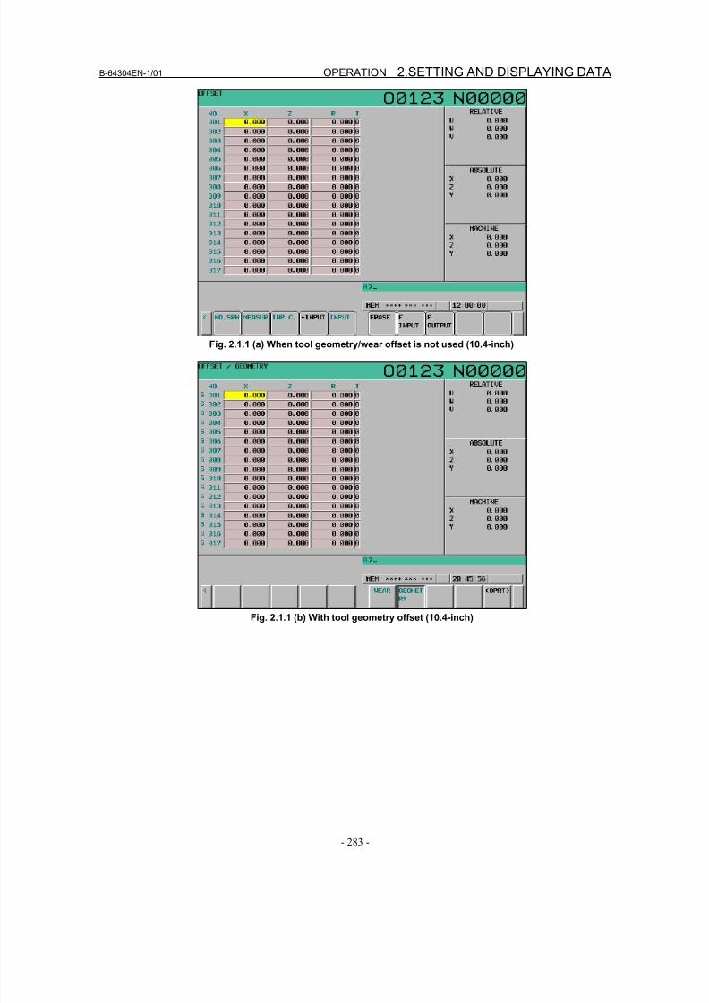
8/16/2019 Manual Operacion para FANUC
http://slidepdf.com/reader/full/manual-operacion-para-fanuc 301/435
B-64304EN-1/01 OPERATION 2.SETTING AND DISPLAYING DATA
- 283 -
Fig. 2.1.1 (a) When tool geometry/wear offset is not used (10.4-inch)
Fig. 2.1.1 (b) With tool geometry offset (10.4-inch)
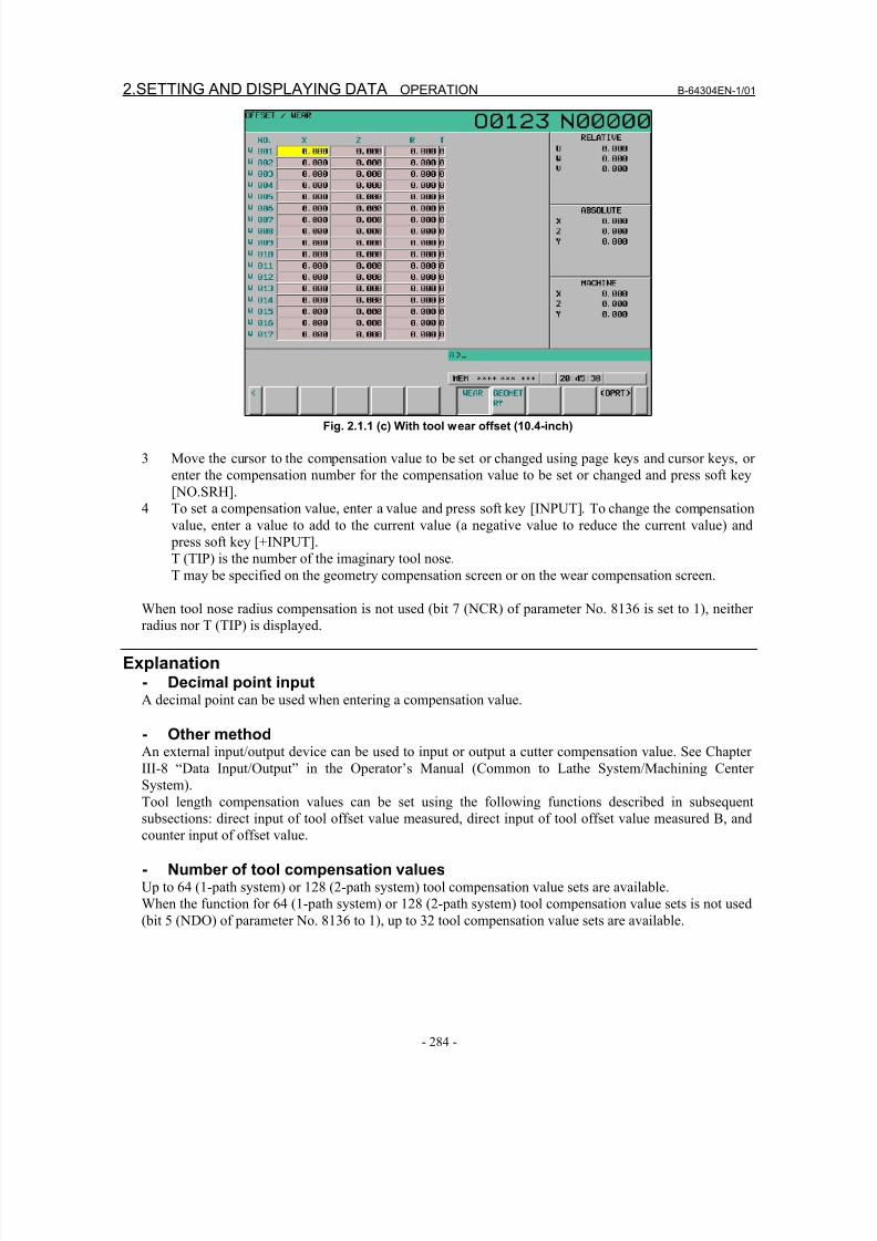
8/16/2019 Manual Operacion para FANUC
http://slidepdf.com/reader/full/manual-operacion-para-fanuc 302/435
2.SETTING AND DISPLAYING DATA OPERATION B-64304EN-1/01
- 284 -
Fig. 2.1.1 (c) With tool wear offset (10.4-inch)
3 Move the cursor to the compensation value to be set or changed using page keys and cursor keys, or
enter the compensation number for the compensation value to be set or changed and press soft key
[NO.SRH].
4 To set a compensation value, enter a value and press soft key [INPUT]. To change the compensation
value, enter a value to add to the current value (a negative value to reduce the current value) and
press soft key [+INPUT].
T (TIP) is the number of the imaginary tool nose.
T may be specified on the geometry compensation screen or on the wear compensation screen.
When tool nose radius compensation is not used (bit 7 (NCR) of parameter No. 8136 is set to 1), neither
radius nor T (TIP) is displayed.
Explanation- Decimal point inputA decimal point can be used when entering a compensation value.
- Other methodAn external input/output device can be used to input or output a cutter compensation value. See Chapter
III-8 “Data Input/Output” in the Operator’s Manual (Common to Lathe System/Machining Center
System).
Tool length compensation values can be set using the following functions described in subsequent
subsections: direct input of tool offset value measured, direct input of tool offset value measured B, and
counter input of offset value.
- Number of tool compensation valuesUp to 64 (1-path system) or 128 (2-path system) tool compensation value sets are available.
When the function for 64 (1-path system) or 128 (2-path system) tool compensation value sets is not used
(bit 5 (NDO) of parameter No. 8136 to 1), up to 32 tool compensation value sets are available.
8/16/2019 Manual Operacion para FANUC
http://slidepdf.com/reader/full/manual-operacion-para-fanuc 303/435
B-64304EN-1/01 OPERATION 2.SETTING AND DISPLAYING DATA
- 285 -
NOTEThe number of tool compensation values can be enhanced to 99 pair (1-pathsystem) or 200 pairs (2-path system) by adding the option.When the option is added, bit 5 (NDO) of parameter No.8136 is invalid.
For each set, tool geometry offset can be distinguished from the tool wear offset. (When bit 6 (NGW) of
parameter No. 8136 is set to 0)
- Disabling entry of compensation valuesIn some cases, tool wear compensation or tool geometry compensation values cannot be input because of
the settings in bits 0 (WOF) and 1 (GOF) of parameter No.3290. The number of the first tool offset
amount of which entry is to be disabled can be set for parameter No. 3294 and the number of tool offset
amounts following the start number can be set for parameter No. 3295 to disable entry of tool offset
amounts within the specified range from the MDI.
Consecutive input values are set as follows:
1) When values are input for offset numbers, starting from one for which input is not inhibited to onefor which input is inhibited, a warning is issued and values are set only for those offset numbers for
which input is not inhibited.
2) When values are input for offset numbers, starting from one for which input is inhibited to one for
which input is not inhibited, a warning is issued and no values are set.
- Displaying radius and T (TIP)When tool nose radius compensation is not used according to the setting, neither radius nor T (TIP) is
displayed. (Bit 7 (NCR) of parameter No. 8136 is set to 1.)
- Changing offset values during automatic operationWhen offset values have been changed during automatic operation, bits 4 (LGT) and 6 (LWM) of
parameter No.5002 can be used for specifying whether new offset values become valid in the next movecommand or in the next T code command.
Fig. 2.1.1 (a)
LGT LWM
When geometry compensation values and
wear compensation values are separately
specified
When geometry compensation values and
wear compensation values are not
separately specified
0 0 Become valid in the next T code block Become valid in the next T code block
1 0 Become valid in the next T code block Become valid in the next T code block
0 1 Become valid in the next T code block Become valid in the next move command
1 1 Become valid in the next move command Become valid in the next move command
2.1.2 Direct Input of Tool Offset Value
To set the difference between the tool reference position used in programming (the nose of the standard
tool, turret center, etc.) and the tool nose position of a tool actually used as an offset value.
Direct input of tool offset value
Procedure- Setting of Z axis offset value1 Cut surface A in manual mode with an actual tool.
Suppose that a workpiece coordinate system has been set.
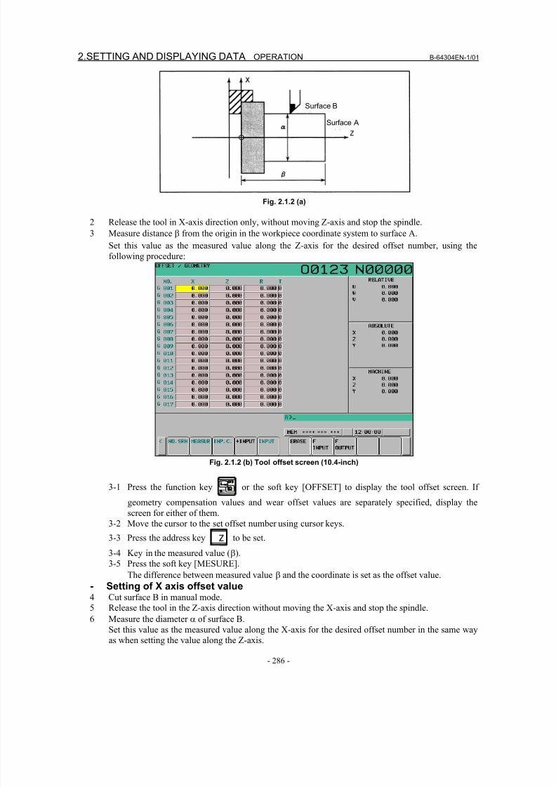
8/16/2019 Manual Operacion para FANUC
http://slidepdf.com/reader/full/manual-operacion-para-fanuc 304/435
2.SETTING AND DISPLAYING DATA OPERATION B-64304EN-1/01
- 286 -
Surface B
Surface A
Fig. 2.1.2 (a)
2 Release the tool in X-axis direction only, without moving Z-axis and stop the spindle.
3 Measure distance β from the origin in the workpiece coordinate system to surface A.
Set this value as the measured value along the Z-axis for the desired offset number, using thefollowing procedure:
Fig. 2.1.2 (b) Tool offset screen (10.4-inch)
3-1 Press the function key or the soft key [OFFSET] to display the tool offset screen. If
geometry compensation values and wear offset values are separately specified, display the
screen for either of them.
3-2 Move the cursor to the set offset number using cursor keys.
3-3 Press the address key to be set.
3-4 Key in the measured value (β).
3-5 Press the soft key [MESURE].
The difference between measured value β and the coordinate is set as the offset value.
- Setting of X axis offset value4 Cut surface B in manual mode.
5 Release the tool in the Z-axis direction without moving the X-axis and stop the spindle.
6 Measure the diameter α of surface B.Set this value as the measured value along the X-axis for the desired offset number in the same way
as when setting the value along the Z-axis.
8/16/2019 Manual Operacion para FANUC
http://slidepdf.com/reader/full/manual-operacion-para-fanuc 305/435
B-64304EN-1/01 OPERATION 2.SETTING AND DISPLAYING DATA
- 287 -
7 Repeat above procedure the same time as the number of the necessary tools.
The offset value is automatically calculated and set.
For example, in case α=69.0 when the coordinate value of surface B in the diagram above is 70.0, set
69.0 [MEASURE] at offset No. 2.
In this case, 1.0 is set as the X-axis offset value to offset No. 2.
Explanation- Offset values for a program created in diameter programmingEnter diameter values for the offset values for axes for which diameter programming is used.
- Tool geometry offset value and tool wear offset valueIf measured values are set on the tool geometry offset screen, all offset values become geometry offset
values and all wear offset values are set to 0. If measured values are set on the tool wear offset screen, the
differences between the measured offset values and the current wear offset values become the new offset
values.
- Release of both axesWhen the record button is provided on the machine side, the tool can be released in the directions of the
two axes by setting bit 2 (PRC) of parameter No. 5005 or using the position record signal. For details on
the position record signal, refer to the manual issued by the machine tool builder.
2.1.3 Direct Input of Tool Offset Value Measured B
Explanation- Basic procedure to set tool offset valueTo use the tool setter function for a one–turret/two–spindle lathe, first specify the spindle to be measured,
using the S2TLS (G040.5) (spindle measurement select) signal.
(1) Execute manual reference position return.
By executing manual reference position return, a machine coordinate system is established.
The tool offset value is computed on the machine coordinate system.
(2) Select manual handle mode or manual continuous feed mode and set the tool compensation value
write mode select signal GOQSM to “1”. The LCD display is automatically changed to the tool
offset screen (geometry), and the “OFST” indicator starts blinking in the status indication area at the
bottom of the screen, which indicates that the tool compensation value writing mode is ready. When
the tool setter function for a one–turret/two–spindle lathe is in use, the S1MES or S2MES (spindle
under measurement) signal, whichever is applicable, becomes 1.
CAUTION After this, it is impossible to switch the S2TLS (spindle measurement selection)signal until the GOQSM (offset write mode) signal becomes 0.
(3) Select a tool to be measured.
(4) When the cursor does not coincide with the tool offset number desired to be set, move the cursor to
the desired offset number using the page key and cursor key.
The cursor can also be coincided with the tool offset number desired to be set automatically by the
tool offset number input signals (when parameter QNI(No.5005#5)=1).
In this case, the position of the cursor cannot be changed on the tool compensation screen using page
keys or cursor keys.
(5) Near the tool to the sensor by manual operation.
(6) Place the tool edge to a contacting surface of the sensor by manual handle feed.Bring the tool edge in contact with the sensor. This causes the tool compensation value writing
signals to input to be CNC.
8/16/2019 Manual Operacion para FANUC
http://slidepdf.com/reader/full/manual-operacion-para-fanuc 306/435
2.SETTING AND DISPLAYING DATA OPERATION B-64304EN-1/01
- 288 -
The following tool compensation amount write signals are set up according to the setting of the bit 3
(TS1)of parameter No. 5004.
When the parameter is 0: +MIT1, –MIT1, +MIT2, –MIT2
When the parameter is 1: +MIT1 only
If the tool compensation value writing signal is set to “1”:
i) The axis is interlocked in this direction and its feed is stopped.
ii) The tool offset value extracted by the tool offset memory (tool geometry offset value) which
corresponds to the offset number shown by the cursor is set up.
(7) For both X-axis and Z-axis, their offset values are set by operations (5) and (6).
(8) Repeat operations (3) to (7) for all necessary tools.
(9) Set the tool compensation value writing mode signal GOQSM to “0”.
The writing mode is canceled and the blinking “OFST” indicator light goes off.
When the tool setter function for a one–turret/two–spindle lathe is in use, the S1MES or S2MES
(spindle under measurement) signal for the spindle being measured becomes 0.
- Basic procedure to set workpiece coordinate shift value
To use the tool setter function for a one–turret/two–spindle lathe, first specify the spindle to be measured,using the S2TLS <G040.5> (spindle measurement select) signal.
(1) Set the tool geometry offset values of each tool in advance.
(2) Execute manual reference position return.
By executing manual reference position return, the machine coordinate system is established.
The workpiece coordinate system shift amount is computed based on the machine coordinate system
of the tool.
(3) Set the workpiece coordinate system shift amount writing mode select signal WOQSM to “1”.
The LCD display automatically switches to the workpiece shifting screen, the “WFST” indicator
starts blinking at the status indicator area in the bottom of the screen, which indicates that the
workpiece coordinate system shift amount writing mode is ready.
When the tool setter function for a one–turret/two–spindle lathe is in use, the workpiece coordinate
system screen is selected, and the S1MES or S2MES (spindle under measurement) signal, whicheveris applicable, becomes 1.
CAUTION After this, it is impossible to switch the S2TLS (spindle measurement selection)signal until the WOQSM (offset write mode) signal becomes 0.
(4) Select a tool to be measured.
(5) Check tool offset numbers.
The tool offset number corresponding to the tool required for measurement, shall be set in the
parameter (No.5020) in advance.
The tool offset number can also be set automatically by setting the tool offset number input signal(with parameter QNI(No.5005#5)=1).
(6) Manually approach the tool to an end face of the workpiece.
(7) Place the tool edge to the end face (sensor) of the workpiece using manual handle feed.
When the tool edge contacts the end face of the workpiece, input the workpiece coordinate system
shift amount signal WOSET.
The workpiece coordinate system shift amount on the Z–axis is automatically set.
(8) Release the tool.
(9) Set the workpiece coordinate system shift amount write mode select signal WOQSM to “0”.
The writing mode is canceled and the blinking “WSFT” indicator light goes off.
When the tool setter function for a one–turret/two–spindle lathe is in use, the S1MES or S2MES
(spindle under measurement) signal, whichever is applicable, becomes 0.
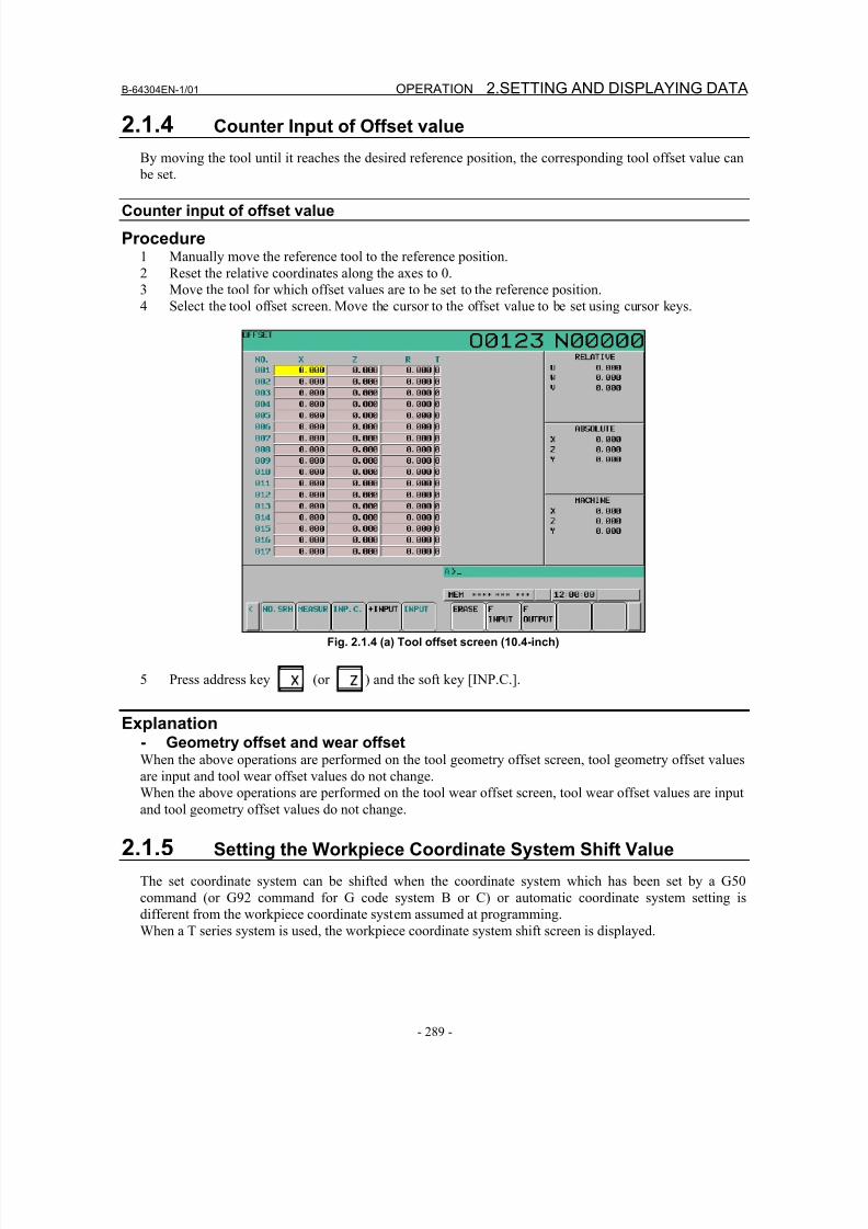
8/16/2019 Manual Operacion para FANUC
http://slidepdf.com/reader/full/manual-operacion-para-fanuc 307/435
B-64304EN-1/01 OPERATION 2.SETTING AND DISPLAYING DATA
- 289 -
2.1.4 Counter Input of Offset value
By moving the tool until it reaches the desired reference position, the corresponding tool offset value can
be set.
Counter input of offset value
Procedure1 Manually move the reference tool to the reference position.
2 Reset the relative coordinates along the axes to 0.
3 Move the tool for which offset values are to be set to the reference position.
4 Select the tool offset screen. Move the cursor to the offset value to be set using cursor keys.
Fig. 2.1.4 (a) Tool offset screen (10.4-inch)
5 Press address key (or ) and the soft key [INP.C.].
Explanation- Geometry offset and wear offsetWhen the above operations are performed on the tool geometry offset screen, tool geometry offset values
are input and tool wear offset values do not change.When the above operations are performed on the tool wear offset screen, tool wear offset values are input
and tool geometry offset values do not change.
2.1.5 Setting the Workpiece Coordinate System Shift Value
The set coordinate system can be shifted when the coordinate system which has been set by a G50
command (or G92 command for G code system B or C) or automatic coordinate system setting is
different from the workpiece coordinate system assumed at programming.
When a T series system is used, the workpiece coordinate system shift screen is displayed.
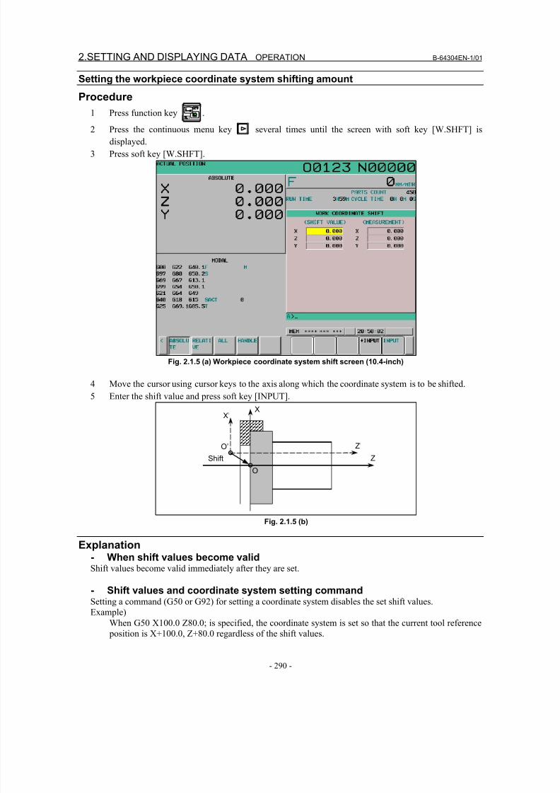
8/16/2019 Manual Operacion para FANUC
http://slidepdf.com/reader/full/manual-operacion-para-fanuc 308/435
2.SETTING AND DISPLAYING DATA OPERATION B-64304EN-1/01
- 290 -
Setting the workpiece coordinate system shifting amount
Procedure
1 Press function key .
2 Press the continuous menu key several times until the screen with soft key [W.SHFT] is
displayed.
3 Press soft key [W.SHFT].
Fig. 2.1.5 (a) Workpiece coordinate system shift screen (10.4-inch)
4 Move the cursor using cursor keys to the axis along which the coordinate system is to be shifted.
5 Enter the shift value and press soft key [INPUT].
X
Z
X’
Z’
O
O’
Shift
Fig. 2.1.5 (b)
Explanation- When shift values become validShift values become valid immediately after they are set.
- Shift values and coordinate system setting commandSetting a command (G50 or G92) for setting a coordinate system disables the set shift values.
Example)
When G50 X100.0 Z80.0; is specified, the coordinate system is set so that the current tool reference position is X+100.0, Z+80.0 regardless of the shift values.
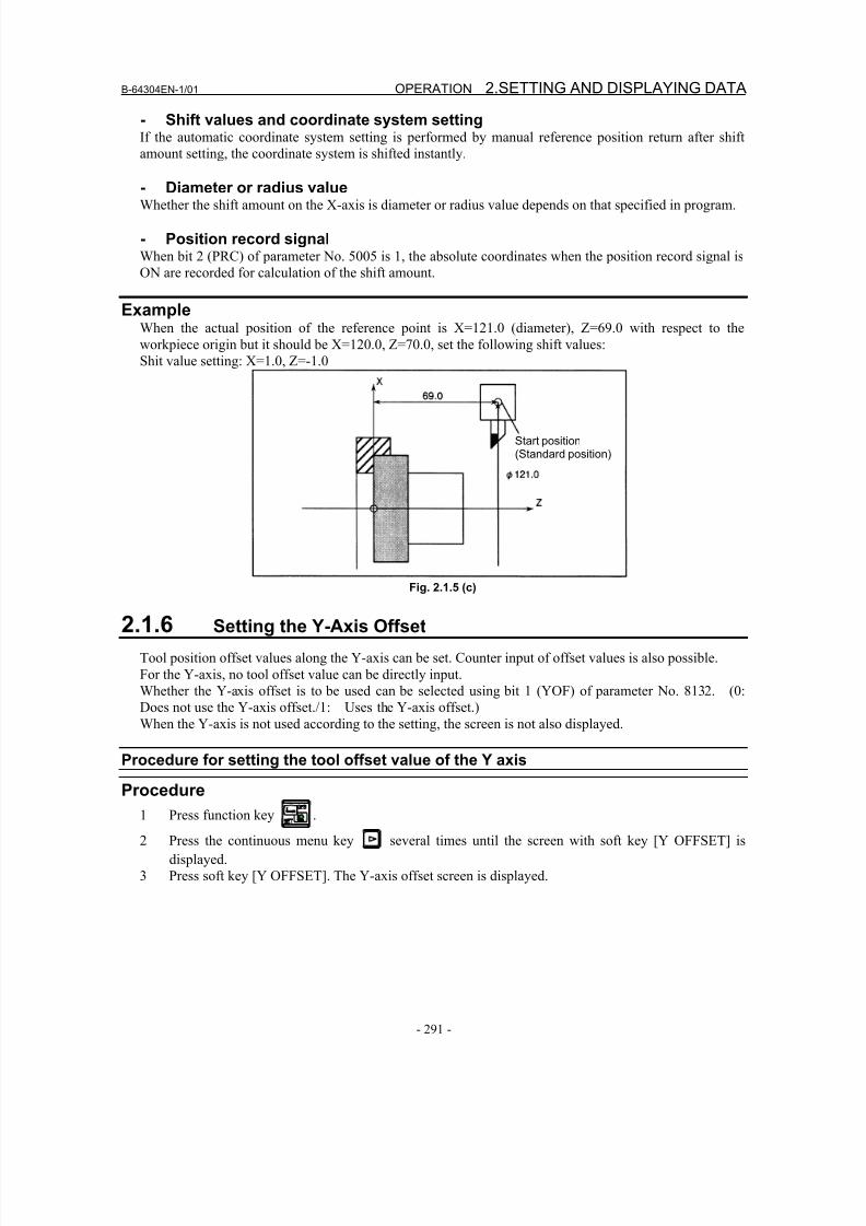
8/16/2019 Manual Operacion para FANUC
http://slidepdf.com/reader/full/manual-operacion-para-fanuc 309/435
B-64304EN-1/01 OPERATION 2.SETTING AND DISPLAYING DATA
- 291 -
- Shift values and coordinate system settingIf the automatic coordinate system setting is performed by manual reference position return after shift
amount setting, the coordinate system is shifted instantly.
- Diameter or radius valueWhether the shift amount on the X-axis is diameter or radius value depends on that specified in program.
- Position record signalWhen bit 2 (PRC) of parameter No. 5005 is 1, the absolute coordinates when the position record signal is
ON are recorded for calculation of the shift amount.
ExampleWhen the actual position of the reference point is X=121.0 (diameter), Z=69.0 with respect to the
workpiece origin but it should be X=120.0, Z=70.0, set the following shift values:
Shit value setting: X=1.0, Z=-1.0
Start position(Standard position)
Fig. 2.1.5 (c)
2.1.6 Setting the Y-Axis Offset
Tool position offset values along the Y-axis can be set. Counter input of offset values is also possible.
For the Y-axis, no tool offset value can be directly input.
Whether the Y-axis offset is to be used can be selected using bit 1 (YOF) of parameter No. 8132. (0:
Does not use the Y-axis offset./1: Uses the Y-axis offset.)
When the Y-axis is not used according to the setting, the screen is not also displayed.
Procedure for setting the tool offset value of the Y axis
Procedure
1 Press function key .
2 Press the continuous menu key several times until the screen with soft key [Y OFFSET] is
displayed.
3 Press soft key [Y OFFSET]. The Y-axis offset screen is displayed.
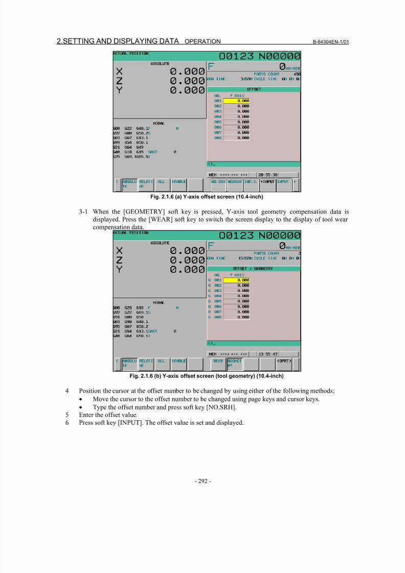
8/16/2019 Manual Operacion para FANUC
http://slidepdf.com/reader/full/manual-operacion-para-fanuc 310/435
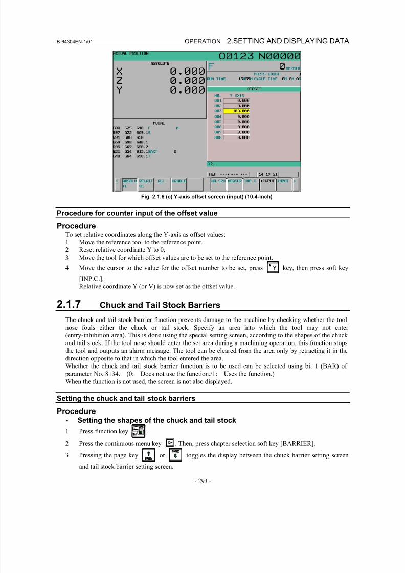
8/16/2019 Manual Operacion para FANUC
http://slidepdf.com/reader/full/manual-operacion-para-fanuc 311/435
B-64304EN-1/01 OPERATION 2.SETTING AND DISPLAYING DATA
- 293 -
Fig. 2.1.6 (c) Y-axis offset screen (input) (10.4-inch)
Procedure for counter input of the offset value
ProcedureTo set relative coordinates along the Y-axis as offset values:
1 Move the reference tool to the reference point.
2 Reset relative coordinate Y to 0.
3 Move the tool for which offset values are to be set to the reference point.
4 Move the cursor to the value for the offset number to be set, press key, then press soft key[INP.C.].
Relative coordinate Y (or V) is now set as the offset value.
2.1.7 Chuck and Tail Stock Barriers
The chuck and tail stock barrier function prevents damage to the machine by checking whether the tool
nose fouls either the chuck or tail stock. Specify an area into which the tool may not enter
(entry-inhibition area). This is done using the special setting screen, according to the shapes of the chuck
and tail stock. If the tool nose should enter the set area during a machining operation, this function stops
the tool and outputs an alarm message. The tool can be cleared from the area only by retracting it in the
direction opposite to that in which the tool entered the area.Whether the chuck and tail stock barrier function is to be used can be selected using bit 1 (BAR) of
parameter No. 8134. (0: Does not use the function./1: Uses the function.)
When the function is not used, the screen is not also displayed.
Setting the chuck and tail stock barriers
Procedure- Setting the shapes of the chuck and tail stock
1 Press function key .
2 Press the continuous menu key . Then, press chapter selection soft key [BARRIER].
3 Pressing the page key or toggles the display between the chuck barrier setting screen
and tail stock barrier setting screen.
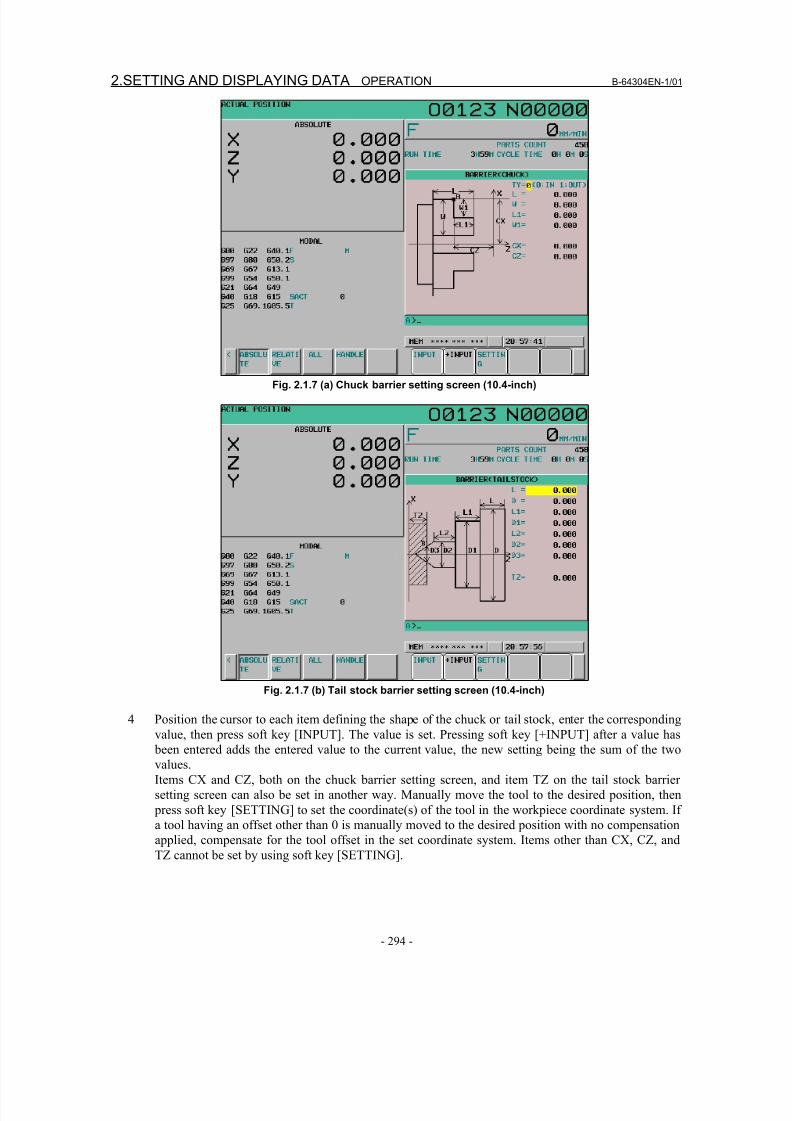
8/16/2019 Manual Operacion para FANUC
http://slidepdf.com/reader/full/manual-operacion-para-fanuc 312/435
2.SETTING AND DISPLAYING DATA OPERATION B-64304EN-1/01
- 294 -
Fig. 2.1.7 (a) Chuck barrier setting screen (10.4-inch)
Fig. 2.1.7 (b) Tail stock barrier setting screen (10.4-inch)
4 Position the cursor to each item defining the shape of the chuck or tail stock, enter the corresponding
value, then press soft key [INPUT]. The value is set. Pressing soft key [+INPUT] after a value has
been entered adds the entered value to the current value, the new setting being the sum of the two
values.
Items CX and CZ, both on the chuck barrier setting screen, and item TZ on the tail stock barrier
setting screen can also be set in another way. Manually move the tool to the desired position, then
press soft key [SETTING] to set the coordinate(s) of the tool in the workpiece coordinate system. If
a tool having an offset other than 0 is manually moved to the desired position with no compensation
applied, compensate for the tool offset in the set coordinate system. Items other than CX, CZ, and
TZ cannot be set by using soft key [SETTING].
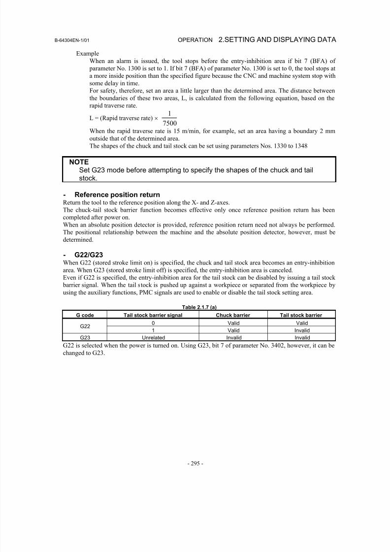
8/16/2019 Manual Operacion para FANUC
http://slidepdf.com/reader/full/manual-operacion-para-fanuc 313/435
B-64304EN-1/01 OPERATION 2.SETTING AND DISPLAYING DATA
- 295 -
Example
When an alarm is issued, the tool stops before the entry-inhibition area if bit 7 (BFA) of
parameter No. 1300 is set to 1. If bit 7 (BFA) of parameter No. 1300 is set to 0, the tool stops at
a more inside position than the specified figure because the CNC and machine system stop with
some delay in time.
For safety, therefore, set an area a little larger than the determined area. The distance between
the boundaries of these two areas, L, is calculated from the following equation, based on the
rapid traverse rate.
L = (Rapid traverse rate) × 7500
1
When the rapid traverse rate is 15 m/min, for example, set an area having a boundary 2 mm
outside that of the determined area.
The shapes of the chuck and tail stock can be set using parameters Nos. 1330 to 1348
NOTE
Set G23 mode before attempting to specify the shapes of the chuck and tailstock.
- Reference position returnReturn the tool to the reference position along the X- and Z-axes.
The chuck-tail stock barrier function becomes effective only once reference position return has been
completed after power on.
When an absolute position detector is provided, reference position return need not always be performed.
The positional relationship between the machine and the absolute position detector, however, must be
determined.
- G22/G23When G22 (stored stroke limit on) is specified, the chuck and tail stock area becomes an entry-inhibition
area. When G23 (stored stroke limit off) is specified, the entry-inhibition area is canceled.
Even if G22 is specified, the entry-inhibition area for the tail stock can be disabled by issuing a tail stock
barrier signal. When the tail stock is pushed up against a workpiece or separated from the workpiece by
using the auxiliary functions, PMC signals are used to enable or disable the tail stock setting area.
Table 2.1.7 (a)
G code Tail stock barrier signal Chuck barrier Tail stock barrier
0 Valid ValidG22
1 Valid Invalid
G23 Unrelated Invalid Invalid
G22 is selected when the power is turned on. Using G23, bit 7 of parameter No. 3402, however, it can bechanged to G23.
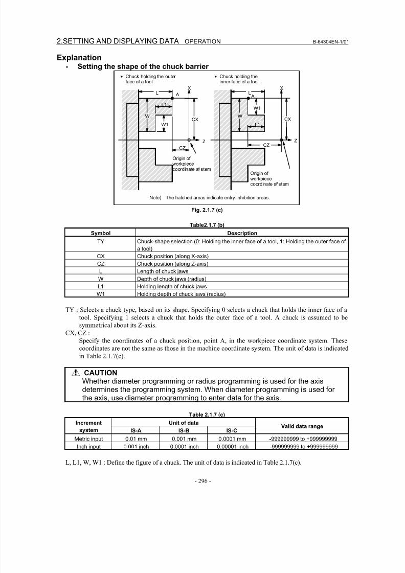
8/16/2019 Manual Operacion para FANUC
http://slidepdf.com/reader/full/manual-operacion-para-fanuc 314/435
2.SETTING AND DISPLAYING DATA OPERATION B-64304EN-1/01
- 296 -
Explanation- Setting the shape of the chuck barrier
• Chuck holding the outerface of a tool
• Chuck holding theinner face of a tool
W
L1
L
W1
CZ
AX
CX
Z
W
L1
L
W1
AX
CX
ZCZ
Origin ofworkpiececoordinate s stem
Note) The hatched areas indicate entry-inhibition areas.
Origin of
workpiececoordinate s stem
Fig. 2.1.7 (c)
Table2.1.7 (b)
Symbol Description
TY Chuck-shape selection (0: Holding the inner face of a tool, 1: Holding the outer face of
a tool)
CX Chuck position (along X-axis)
CZ Chuck position (along Z-axis)
L Length of chuck jaws
W Depth of chuck jaws (radius)
L1 Holding length of chuck jaws
W1 Holding depth of chuck jaws (radius)
TY : Selects a chuck type, based on its shape. Specifying 0 selects a chuck that holds the inner face of a
tool. Specifying 1 selects a chuck that holds the outer face of a tool. A chuck is assumed to be
symmetrical about its Z-axis.
CX, CZ :
Specify the coordinates of a chuck position, point A, in the workpiece coordinate system. These
coordinates are not the same as those in the machine coordinate system. The unit of data is indicated
in Table 2.1.7(c).
CAUTIONWhether diameter programming or radius programming is used for the axisdetermines the programming system. When diameter programming is used forthe axis, use diameter programming to enter data for the axis.
Table 2.1.7 (c)
Unit of dataIncrement
system IS-A IS-B IS-CValid data range
Metric input 0.01 mm 0.001 mm 0.0001 mm -999999999 to +999999999
Inch input 0.001 inch 0.0001 inch 0.00001 inch -999999999 to +999999999
L, L1, W, W1 : Define the figure of a chuck. The unit of data is indicated in Table 2.1.7(c).
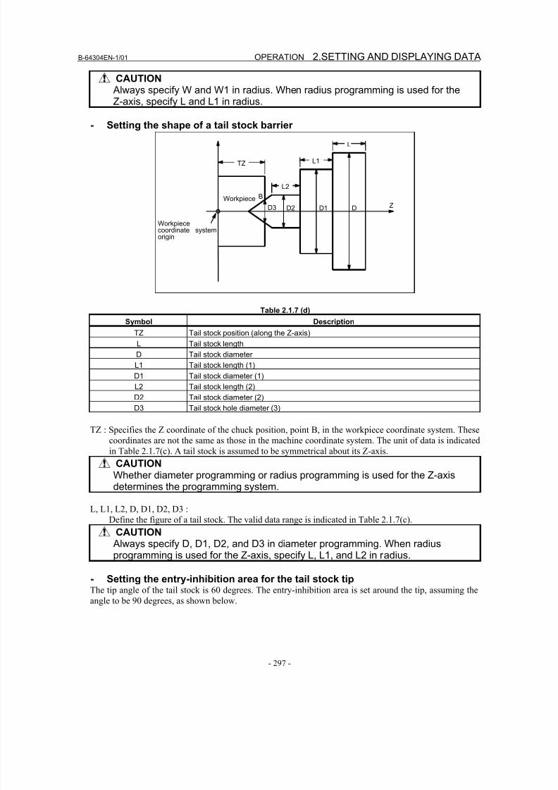
8/16/2019 Manual Operacion para FANUC
http://slidepdf.com/reader/full/manual-operacion-para-fanuc 315/435
B-64304EN-1/01 OPERATION 2.SETTING AND DISPLAYING DATA
- 297 -
CAUTION Always specify W and W1 in radius. When radius programming is used for theZ-axis, specify L and L1 in radius.
- Setting the shape of a tail stock barrier
Z
Workpiececoordinate systemorigin
L
L1
L2
D3 D2 D1 D
TZ
Workpiece B
Table 2.1.7 (d)
Symbol Description
TZ Tail stock position (along the Z-axis)
L Tail stock length
D Tail stock diameter
L1 Tail stock length (1)
D1 Tail stock diameter (1)
L2 Tail stock length (2)
D2 Tail stock diameter (2)
D3 Tail stock hole diameter (3)
TZ : Specifies the Z coordinate of the chuck position, point B, in the workpiece coordinate system. These
coordinates are not the same as those in the machine coordinate system. The unit of data is indicated
in Table 2.1.7(c). A tail stock is assumed to be symmetrical about its Z-axis.
CAUTIONWhether diameter programming or radius programming is used for the Z-axisdetermines the programming system.
L, L1, L2, D, D1, D2, D3 :
Define the figure of a tail stock. The valid data range is indicated in Table 2.1.7(c).
CAUTION Always specify D, D1, D2, and D3 in diameter programming. When radiusprogramming is used for the Z-axis, specify L, L1, and L2 in radius.
- Setting the entry-inhibition area for the tail stock tipThe tip angle of the tail stock is 60 degrees. The entry-inhibition area is set around the tip, assuming the
angle to be 90 degrees, as shown below.
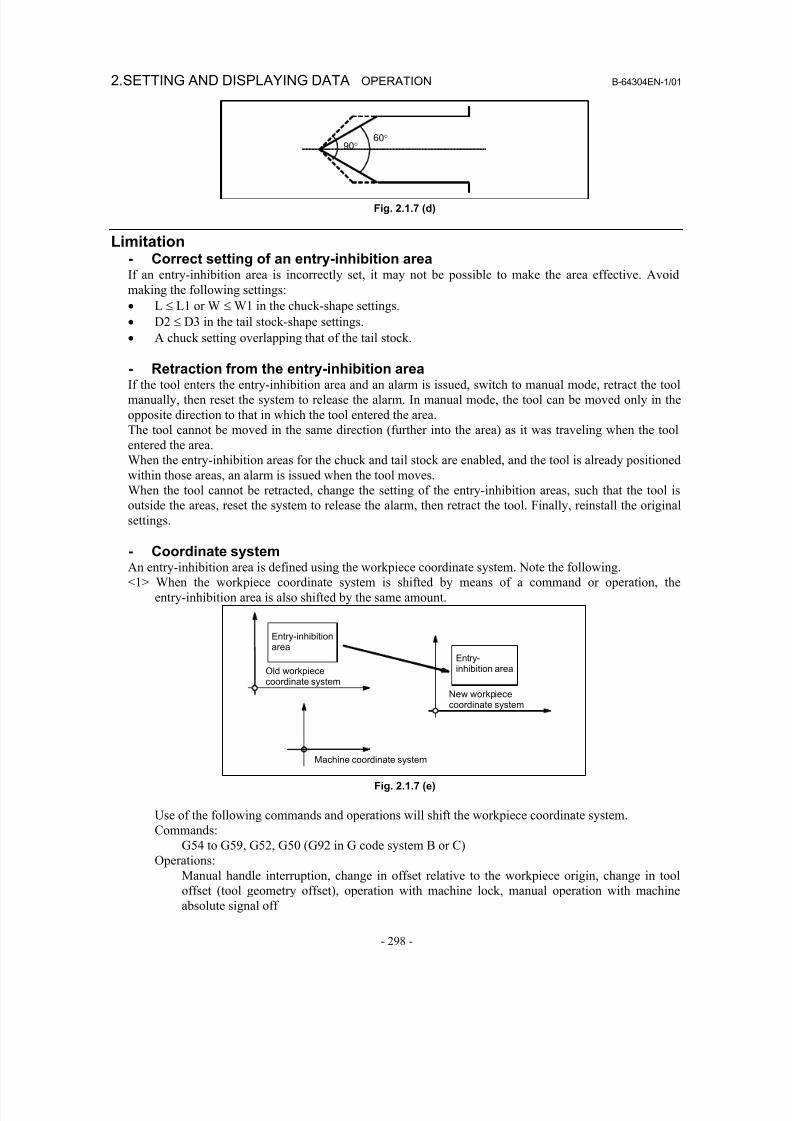
8/16/2019 Manual Operacion para FANUC
http://slidepdf.com/reader/full/manual-operacion-para-fanuc 316/435
2.SETTING AND DISPLAYING DATA OPERATION B-64304EN-1/01
- 298 -
90°60°
Fig. 2.1.7 (d)
Limitation- Correct setting of an entry-inhibition areaIf an entry-inhibition area is incorrectly set, it may not be possible to make the area effective. Avoid
making the following settings:
• L ≤ L1 or W ≤ W1 in the chuck-shape settings.
• D2 ≤ D3 in the tail stock-shape settings.
• A chuck setting overlapping that of the tail stock.
- Retraction from the entry-inhibition areaIf the tool enters the entry-inhibition area and an alarm is issued, switch to manual mode, retract the tool
manually, then reset the system to release the alarm. In manual mode, the tool can be moved only in the
opposite direction to that in which the tool entered the area.
The tool cannot be moved in the same direction (further into the area) as it was traveling when the tool
entered the area.
When the entry-inhibition areas for the chuck and tail stock are enabled, and the tool is already positioned
within those areas, an alarm is issued when the tool moves.
When the tool cannot be retracted, change the setting of the entry-inhibition areas, such that the tool is
outside the areas, reset the system to release the alarm, then retract the tool. Finally, reinstall the original
settings.
- Coordinate systemAn entry-inhibition area is defined using the workpiece coordinate system. Note the following.
<1> When the workpiece coordinate system is shifted by means of a command or operation, the
entry-inhibition area is also shifted by the same amount.
Machine coordinate system
Entry-inhibitionarea
Old workpiececoordinate system
Entry-inhibition area
New workpiece
coordinate system
Fig. 2.1.7 (e)
Use of the following commands and operations will shift the workpiece coordinate system.
Commands:
G54 to G59, G52, G50 (G92 in G code system B or C)
Operations:
Manual handle interruption, change in offset relative to the workpiece origin, change in tooloffset (tool geometry offset), operation with machine lock, manual operation with machine
absolute signal off

8/16/2019 Manual Operacion para FANUC
http://slidepdf.com/reader/full/manual-operacion-para-fanuc 317/435
B-64304EN-1/01 OPERATION 2.SETTING AND DISPLAYING DATA
- 299 -
<2> When the tool enters an entry-inhibition area during automatic operation, set the manual absolute
signal, *ABSM, to 0 (on), then manually retract the tool from the area. If this signal is 1, the distance
the tool moves in manual operation is not counted in the tool coordinates in the workpiece
coordinate system. This results in the state where the tool can never be retracted from the
entry-inhibition area.
- Stored stroke check 2/3When both stored stroke check 2/3 and the chuck tail stock barrier function are provided, the barrier takes
priority over the stored stroke check. Stored stroke check 2/3 is ignored.

8/16/2019 Manual Operacion para FANUC
http://slidepdf.com/reader/full/manual-operacion-para-fanuc 318/435

8/16/2019 Manual Operacion para FANUC
http://slidepdf.com/reader/full/manual-operacion-para-fanuc 319/435
APPENDIX

8/16/2019 Manual Operacion para FANUC
http://slidepdf.com/reader/full/manual-operacion-para-fanuc 320/435
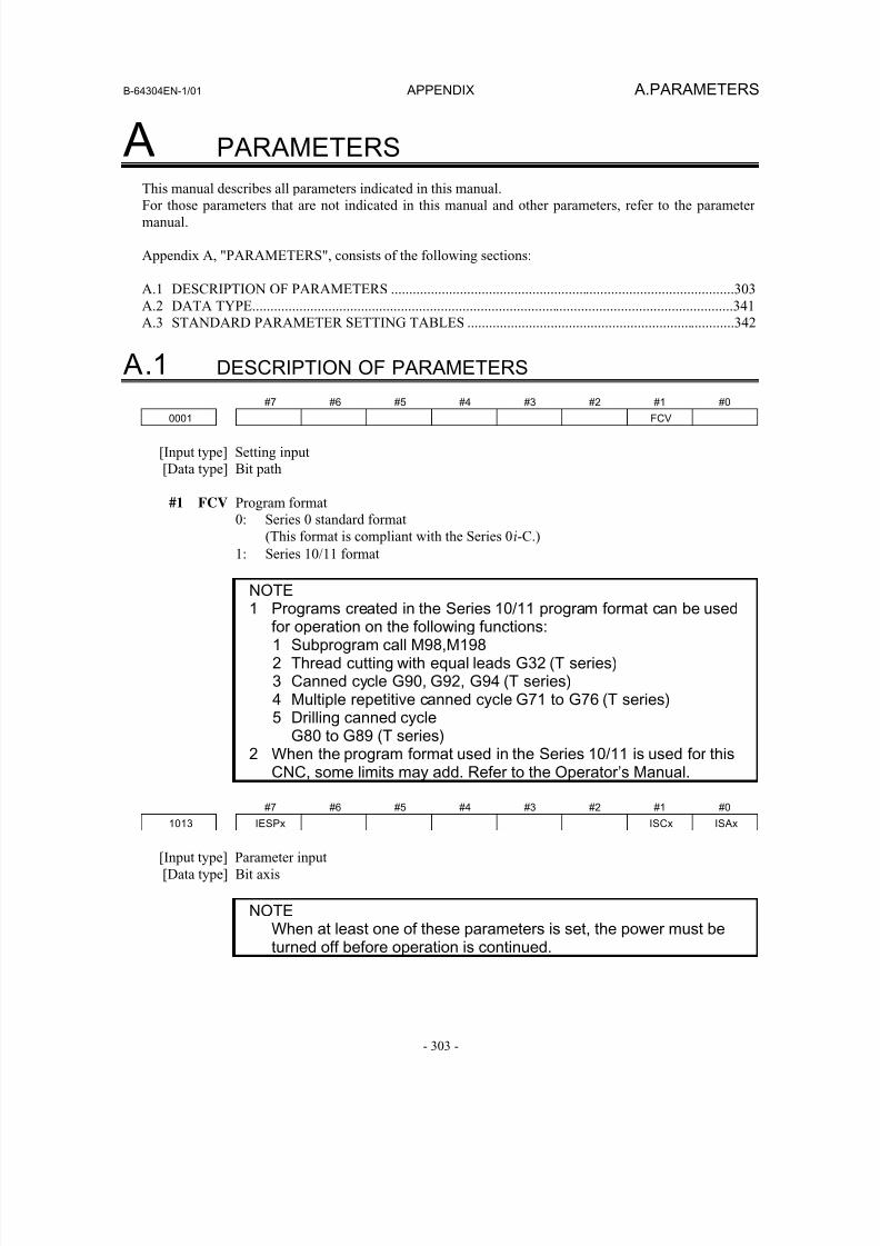
8/16/2019 Manual Operacion para FANUC
http://slidepdf.com/reader/full/manual-operacion-para-fanuc 321/435
B-64304EN-1/01 APPENDIX A.PARAMETERS
- 303 -
A PARAMETERS
This manual describes all parameters indicated in this manual.For those parameters that are not indicated in this manual and other parameters, refer to the parameter
manual.
Appendix A, "PARAMETERS", consists of the following sections:
A.1 DESCRIPTION OF PARAMETERS ...............................................................................................303
A.2 DATA TYPE.....................................................................................................................................341
A.3 STANDARD PARAMETER SETTING TABLES ..........................................................................342
A.1 DESCRIPTION OF PARAMETERS
#7 #6 #5 #4 #3 #2 #1 #0
0001 FCV
[Input type] Setting input
[Data type] Bit path
#1 FCV Program format
0: Series 0 standard format
(This format is compliant with the Series 0i-C.)
1: Series 10/11 format
NOTE1 Programs created in the Series 10/11 program format can be used
for operation on the following functions:1 Subprogram call M98,M1982 Thread cutting with equal leads G32 (T series)3 Canned cycle G90, G92, G94 (T series)4 Multiple repetitive canned cycle G71 to G76 (T series)5 Drilling canned cycle
G80 to G89 (T series)2 When the program format used in the Series 10/11 is used for this
CNC, some limits may add. Refer to the Operator’s Manual.
#7 #6 #5 #4 #3 #2 #1 #0
1013 IESPx ISCx ISAx
[Input type] Parameter input
[Data type] Bit axis
NOTEWhen at least one of these parameters is set, the power must beturned off before operation is continued.
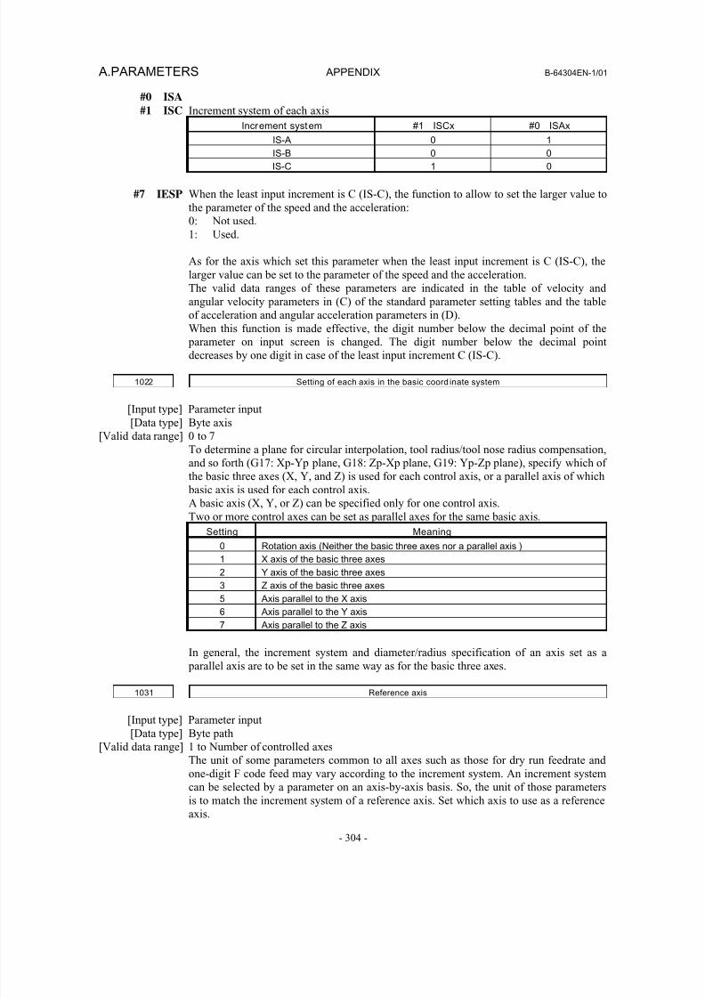
8/16/2019 Manual Operacion para FANUC
http://slidepdf.com/reader/full/manual-operacion-para-fanuc 322/435
A.PARAMETERS APPENDIX B-64304EN-1/01
- 304 -
#0 ISA
#1 ISC Increment system of each axis
Increment system #1 ISCx #0 ISAx
IS-A 0 1
IS-B 0 0IS-C 1 0
#7 IESP When the least input increment is C (IS-C), the function to allow to set the larger value to
the parameter of the speed and the acceleration:
0: Not used.
1: Used.
As for the axis which set this parameter when the least input increment is C (IS-C), the
larger value can be set to the parameter of the speed and the acceleration.
The valid data ranges of these parameters are indicated in the table of velocity and
angular velocity parameters in (C) of the standard parameter setting tables and the table
of acceleration and angular acceleration parameters in (D).When this function is made effective, the digit number below the decimal point of the
parameter on input screen is changed. The digit number below the decimal point
decreases by one digit in case of the least input increment C (IS-C).
1022 Setting of each axis in the basic coord inate system
[Input type] Parameter input
[Data type] Byte axis
[Valid data range] 0 to 7
To determine a plane for circular interpolation, tool radius/tool nose radius compensation,
and so forth (G17: Xp-Yp plane, G18: Zp-Xp plane, G19: Yp-Zp plane), specify which of
the basic three axes (X, Y, and Z) is used for each control axis, or a parallel axis of which
basic axis is used for each control axis.
A basic axis (X, Y, or Z) can be specified only for one control axis.
Two or more control axes can be set as parallel axes for the same basic axis.
Setting Meaning
0 Rotation axis (Neither the basic three axes nor a parallel axis )
1 X axis of the basic three axes
2 Y axis of the basic three axes
3 Z axis of the basic three axes
5 Axis parallel to the X axis
6 Axis parallel to the Y axis
7 Axis parallel to the Z axis
In general, the increment system and diameter/radius specification of an axis set as a
parallel axis are to be set in the same way as for the basic three axes.
1031 Reference axis
[Input type] Parameter input
[Data type] Byte path
[Valid data range] 1 to Number of controlled axes
The unit of some parameters common to all axes such as those for dry run feedrate and
one-digit F code feed may vary according to the increment system. An increment system
can be selected by a parameter on an axis-by-axis basis. So, the unit of those parametersis to match the increment system of a reference axis. Set which axis to use as a reference
axis.
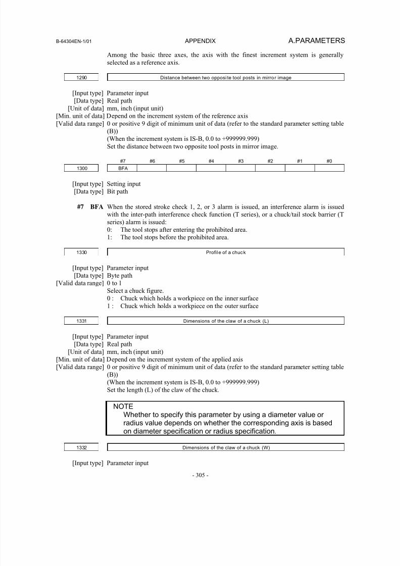
8/16/2019 Manual Operacion para FANUC
http://slidepdf.com/reader/full/manual-operacion-para-fanuc 323/435
B-64304EN-1/01 APPENDIX A.PARAMETERS
- 305 -
Among the basic three axes, the axis with the finest increment system is generally
selected as a reference axis.
1290 Distance between two opposi te tool posts in mirro r image
[Input type] Parameter input
[Data type] Real path
[Unit of data] mm, inch (input unit)
[Min. unit of data] Depend on the increment system of the reference axis
[Valid data range] 0 or positive 9 digit of minimum unit of data (refer to the standard parameter setting table
(B))
(When the increment system is IS-B, 0.0 to +999999.999)
Set the distance between two opposite tool posts in mirror image.
#7 #6 #5 #4 #3 #2 #1 #0
1300 BFA
[Input type] Setting input
[Data type] Bit path
#7 BFA When the stored stroke check 1, 2, or 3 alarm is issued, an interference alarm is issued
with the inter-path interference check function (T series), or a chuck/tail stock barrier (T
series) alarm is issued:
0: The tool stops after entering the prohibited area.
1: The tool stops before the prohibited area.
1330 Profil e of a chuck
[Input type] Parameter input[Data type] Byte path
[Valid data range] 0 to 1
Select a chuck figure.
0 : Chuck which holds a workpiece on the inner surface
1 : Chuck which holds a workpiece on the outer surface
1331 Dimensions of the claw of a chuck (L)
[Input type] Parameter input
[Data type] Real path
[Unit of data] mm, inch (input unit)
[Min. unit of data] Depend on the increment system of the applied axis
[Valid data range] 0 or positive 9 digit of minimum unit of data (refer to the standard parameter setting table
(B))
(When the increment system is IS-B, 0.0 to +999999.999)
Set the length (L) of the claw of the chuck.
NOTEWhether to specify this parameter by using a diameter value orradius value depends on whether the corresponding axis is basedon diameter specification or radius specification.
1332 Dimensions of the claw of a chuck (W)
[Input type] Parameter input
8/16/2019 Manual Operacion para FANUC
http://slidepdf.com/reader/full/manual-operacion-para-fanuc 324/435
A.PARAMETERS APPENDIX B-64304EN-1/01
- 306 -
[Data type] Real path
[Unit of data] mm, inch (input unit)
[Min. unit of data] Depend on the increment system of the applied axis
[Valid data range] 0 or positive 9 digit of minimum unit of data (refer to the standard parameter setting table
(B))
(When the increment system is IS-B, 0.0 to +999999.999)
Set the width (W) of the claw of the chuck.
NOTESpecify this parameter by using a radius value at all times.
1333 Dimensions of the claw of a chuck (L1)
[Input type] Parameter input
[Data type] Real path
[Unit of data] mm, inch (input unit)
[Min. unit of data] Depend on the increment system of the applied axis[Valid data range] 0 or positive 9 digit of minimum unit of data (refer to the standard parameter setting table
(B))
(When the increment system is IS-B, 0.0 to +999999.999)
Set the length (L1) of the claw of the chuck.
NOTEWhether to specify this parameter by using a diameter value orradius value depends on whether the corresponding axis is basedon diameter specification or radius specification.
1334 Dimensions of the claw of a chuck (W1)
[Input type] Parameter input
[Data type] Real path
[Unit of data] mm, inch (input unit)
[Min. unit of data] Depend on the increment system of the applied axis
[Valid data range] 0 or positive 9 digit of minimum unit of data (refer to the standard parameter setting table
(B))
(When the increment system is IS-B, 0.0 to +999999.999)
Set the width (W1) of the claw of the chuck.
NOTESpecify this parameter by using a radius value at all times.
1335 X coord inate of a chuck (CX)
[Input type] Parameter input
[Data type] Real path
[Unit of data] mm, inch (input unit)
[Min. unit of data] Depend on the increment system of the applied axis
[Valid data range] 9 digit of minimum unit of data (refer to standard parameter setting table (A))
(When the increment system is IS-B, -999999.999 to +999999.999)
Set the chuck position (X coordinate) in the workpiece coordinate system.
8/16/2019 Manual Operacion para FANUC
http://slidepdf.com/reader/full/manual-operacion-para-fanuc 325/435
B-64304EN-1/01 APPENDIX A.PARAMETERS
- 307 -
NOTEWhether to specify this parameter by using a diameter value orradius value depends on whether the corresponding axis is basedon diameter specification or radius specification.
1336 Z coord inate of a chuck (CZ)
[Input type] Parameter input
[Data type] Real path
[Unit of data] mm, inch (input unit)
[Min. unit of data] Depend on the increment system of the applied axis
[Valid data range] 9 digit of minimum unit of data (refer to standard parameter setting table (A))
(When the increment system is IS-B, -999999.999 to +999999.999)
Set the chuck position (Z coordinate) in the workpiece coordinate system.
NOTEWhether to specify this parameter by using a diameter value orradius value depends on whether the corresponding axis is basedon diameter specification or radius specification.
1341 Length of a tail stock (L)
[Input type] Parameter input
[Data type] Real path
[Unit of data] mm, inch (input unit)
[Min. unit of data] Depend on the increment system of the applied axis
[Valid data range] 0 or positive 9 digit of minimum unit of data (refer to the standard parameter setting table
(B))
(When the increment system is IS-B, 0.0 to +999999.999)
Set the length (L) of the tail stock.
NOTEWhether to specify this parameter by using a diameter value orradius value depends on whether the corresponding axis is basedon diameter specification or radius specification.
1342 Diameter of a tail stock (D)
[Input type] Parameter input
[Data type] Real path
[Unit of data] mm, inch (input unit)
[Min. unit of data] Depend on the increment system of the applied axis
[Valid data range] 0 or positive 9 digit of minimum unit of data (refer to the standard parameter setting table
(B))
(When the increment system is IS-B, 0.0 to +999999.999)
Set the diameter (D) of the tail stock.
NOTESpecify this parameter by using a diameter value at all times.
8/16/2019 Manual Operacion para FANUC
http://slidepdf.com/reader/full/manual-operacion-para-fanuc 326/435
A.PARAMETERS APPENDIX B-64304EN-1/01
- 308 -
1343 Length of a tail stock (L1)
[Input type] Parameter input
[Data type] Real path
[Unit of data] mm, inch (input unit)[Min. unit of data] Depend on the increment system of the applied axis
[Valid data range] 0 or positive 9 digit of minimum unit of data (refer to the standard parameter setting table
(B))
(When the increment system is IS-B, 0.0 to +999999.999)
Set the length (L1) of the tail stock.
NOTEWhether to specify this parameter by using a diameter value orradius value depends on whether the corresponding axis is basedon diameter specification or radius specification.
1344 Diameter of a tail stock (D1)
[Input type] Parameter input
[Data type] Real path
[Unit of data] mm, inch (input unit)
[Min. unit of data] Depend on the increment system of the applied axis
[Valid data range] 0 or positive 9 digit of minimum unit of data (refer to the standard parameter setting table
(B))
(When the increment system is IS-B, 0.0 to +999999.999)
Set the diameter (D1) of the tail stock.
NOTESpecify this parameter by using a diameter value at all times.
1345 Length of a tail stock (L2)
[Input type] Parameter input
[Data type] Real path
[Unit of data] mm, inch (input unit)
[Min. unit of data] Depend on the increment system of the applied axis
[Valid data range] 0 or positive 9 digit of minimum unit of data (refer to the standard parameter setting table
(B))
(When the increment system is IS-B, 0.0 to +999999.999)Set the length (L2) of the tail stock.
NOTEWhether to specify this parameter by using a diameter value orradius value depends on whether the corresponding axis is basedon diameter specification or radius specification.
1346 Diameter of a tail stock (D2)
[Input type] Parameter input
[Data type] Real path
[Unit of data] mm, inch (input unit)
[Min. unit of data] Depend on the increment system of the applied axis
8/16/2019 Manual Operacion para FANUC
http://slidepdf.com/reader/full/manual-operacion-para-fanuc 327/435
B-64304EN-1/01 APPENDIX A.PARAMETERS
- 309 -
[Valid data range] 0 or positive 9 digit of minimum unit of data (refer to the standard parameter setting table
(B))
(When the increment system is IS-B, 0.0 to +999999.999)
Set the diameter (D2) of the tail stock.
NOTESpecify this parameter by using a diameter value at all times.
1347 Diameter of the hole of a tail stock (D3)
[Input type] Parameter input
[Data type] Real path
[Unit of data] mm, inch (input unit)
[Min. unit of data] Depend on the increment system of the applied axis
[Valid data range] 0 or positive 9 digit of minimum unit of data (refer to the standard parameter setting table
(B))
(When the increment system is IS-B, 0.0 to +999999.999)Set the diameter (D3) of the tail stock.
NOTESpecify this parameter by using a diameter value at all times.
1348 Z coord inate of a tail stock (TZ)
[Input type] Parameter input
[Data type] Real path
[Unit of data] mm, inch (input unit)
[Min. unit of data] Depend on the increment system of the applied axis[Valid data range] 9 digit of minimum unit of data (refer to standard parameter setting table (A))
(When the increment system is IS-B, -999999.999 to +999999.999)
Set the tail stock position (Z coordinate) in the workpiece coordinate system.
NOTEWhether to specify this parameter by using a diameter value orradius value depends on whether the corresponding axis is basedon diameter specification or radius specification.
#7 #6 #5 #4 #3 #2 #1 #0
1401 RF0 LRP
[Input type] Parameter input
[Data type] Bit path
#1 LRP Positioning (G00)
0: Positioning is performed with non-linear type positioning so that the tool moves
along each axis independently at rapid traverse.
1: Positioning is performed with linear interpolation so that the tool moves in a straight
line.
#4 RF0 When cutting feedrate override is 0% during rapid traverse,
0: The machine tool does not stop moving.1: The machine tool stops moving.
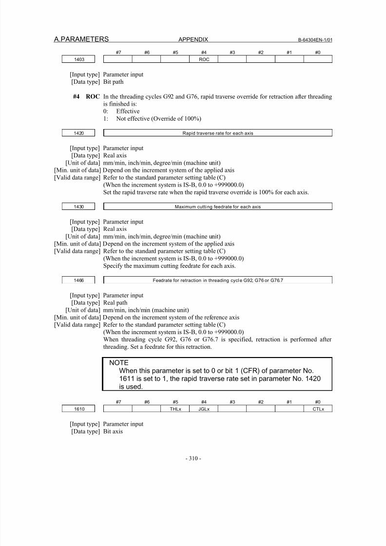
8/16/2019 Manual Operacion para FANUC
http://slidepdf.com/reader/full/manual-operacion-para-fanuc 328/435
A.PARAMETERS APPENDIX B-64304EN-1/01
- 310 -
#7 #6 #5 #4 #3 #2 #1 #0
1403 ROC
[Input type] Parameter input
[Data type] Bit path
#4 ROC In the threading cycles G92 and G76, rapid traverse override for retraction after threading
is finished is:
0: Effective
1: Not effective (Override of 100%)
1420 Rapid traverse rate for each axis
[Input type] Parameter input
[Data type] Real axis
[Unit of data] mm/min, inch/min, degree/min (machine unit)
[Min. unit of data] Depend on the increment system of the applied axis[Valid data range] Refer to the standard parameter setting table (C)
(When the increment system is IS-B, 0.0 to +999000.0)
Set the rapid traverse rate when the rapid traverse override is 100% for each axis.
1430 Maximum cutti ng feedrate for each axis
[Input type] Parameter input
[Data type] Real axis
[Unit of data] mm/min, inch/min, degree/min (machine unit)
[Min. unit of data] Depend on the increment system of the applied axis
[Valid data range] Refer to the standard parameter setting table (C)
(When the increment system is IS-B, 0.0 to +999000.0)Specify the maximum cutting feedrate for each axis.
1466 Feedrate for retraction in threading cycle G92, G76 or G76.7
[Input type] Parameter input
[Data type] Real path
[Unit of data] mm/min, inch/min (machine unit)
[Min. unit of data] Depend on the increment system of the reference axis
[Valid data range] Refer to the standard parameter setting table (C)
(When the increment system is IS-B, 0.0 to +999000.0)
When threading cycle G92, G76 or G76.7 is specified, retraction is performed after
threading. Set a feedrate for this retraction.
NOTEWhen this parameter is set to 0 or bit 1 (CFR) of parameter No.1611 is set to 1, the rapid traverse rate set in parameter No. 1420is used.
#7 #6 #5 #4 #3 #2 #1 #0
1610 THLx JGLx CTLx
[Input type] Parameter input
[Data type] Bit axis
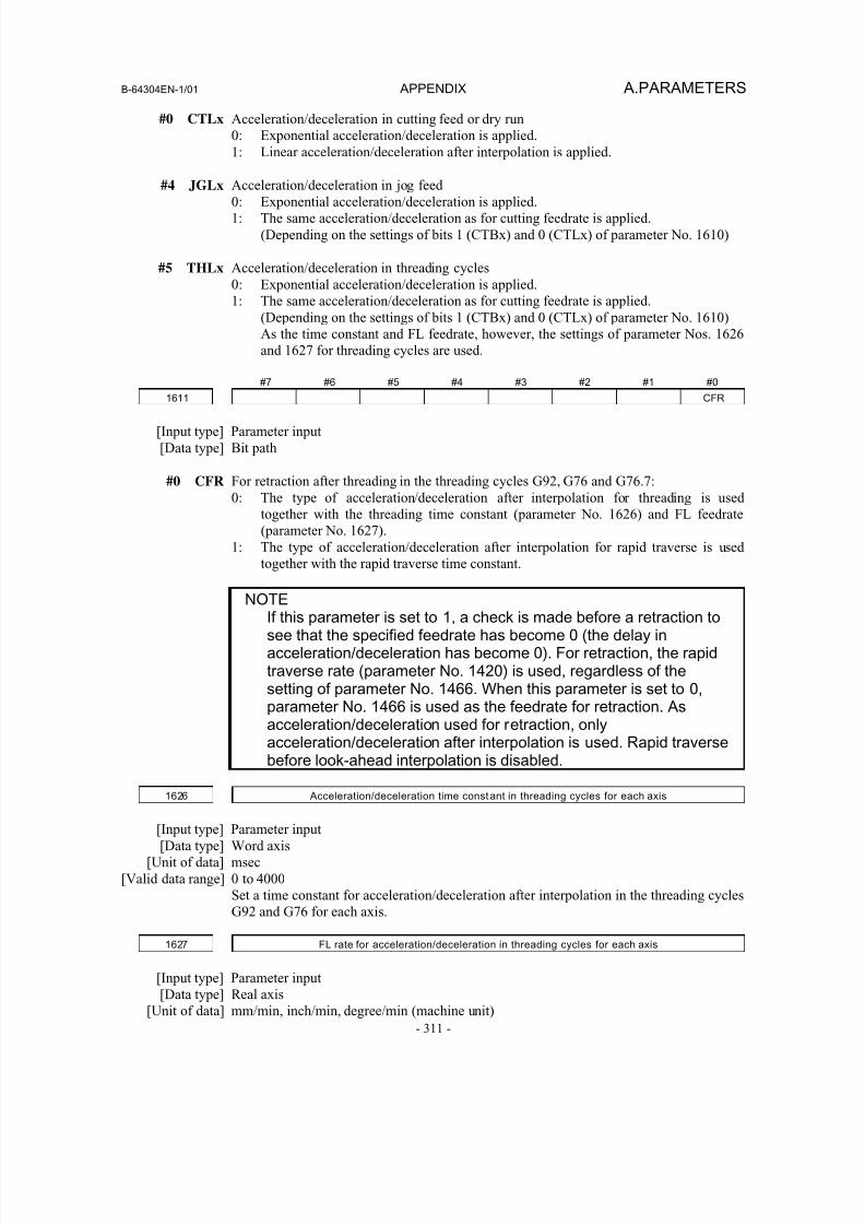
8/16/2019 Manual Operacion para FANUC
http://slidepdf.com/reader/full/manual-operacion-para-fanuc 329/435
B-64304EN-1/01 APPENDIX A.PARAMETERS
- 311 -
#0 CTLx Acceleration/deceleration in cutting feed or dry run
0: Exponential acceleration/deceleration is applied.
1: Linear acceleration/deceleration after interpolation is applied.
#4 JGLx Acceleration/deceleration in jog feed0: Exponential acceleration/deceleration is applied.
1: The same acceleration/deceleration as for cutting feedrate is applied.
(Depending on the settings of bits 1 (CTBx) and 0 (CTLx) of parameter No. 1610)
#5 THLx Acceleration/deceleration in threading cycles
0: Exponential acceleration/deceleration is applied.
1: The same acceleration/deceleration as for cutting feedrate is applied.
(Depending on the settings of bits 1 (CTBx) and 0 (CTLx) of parameter No. 1610)
As the time constant and FL feedrate, however, the settings of parameter Nos. 1626
and 1627 for threading cycles are used.
#7 #6 #5 #4 #3 #2 #1 #01611 CFR
[Input type] Parameter input
[Data type] Bit path
#0 CFR For retraction after threading in the threading cycles G92, G76 and G76.7:
0: The type of acceleration/deceleration after interpolation for threading is used
together with the threading time constant (parameter No. 1626) and FL feedrate
(parameter No. 1627).
1: The type of acceleration/deceleration after interpolation for rapid traverse is used
together with the rapid traverse time constant.
NOTEIf this parameter is set to 1, a check is made before a retraction tosee that the specified feedrate has become 0 (the delay inacceleration/deceleration has become 0). For retraction, the rapidtraverse rate (parameter No. 1420) is used, regardless of thesetting of parameter No. 1466. When this parameter is set to 0,parameter No. 1466 is used as the feedrate for retraction. Asacceleration/deceleration used for retraction, onlyacceleration/deceleration after interpolation is used. Rapid traversebefore look-ahead interpolation is disabled.
1626 Acceleration/deceleration time constant in threading cycles for each axis
[Input type] Parameter input
[Data type] Word axis
[Unit of data] msec
[Valid data range] 0 to 4000
Set a time constant for acceleration/deceleration after interpolation in the threading cycles
G92 and G76 for each axis.
1627 FL rate for acceleration/deceleration in threading cycles for each axis
[Input type] Parameter input
[Data type] Real axis
[Unit of data] mm/min, inch/min, degree/min (machine unit)
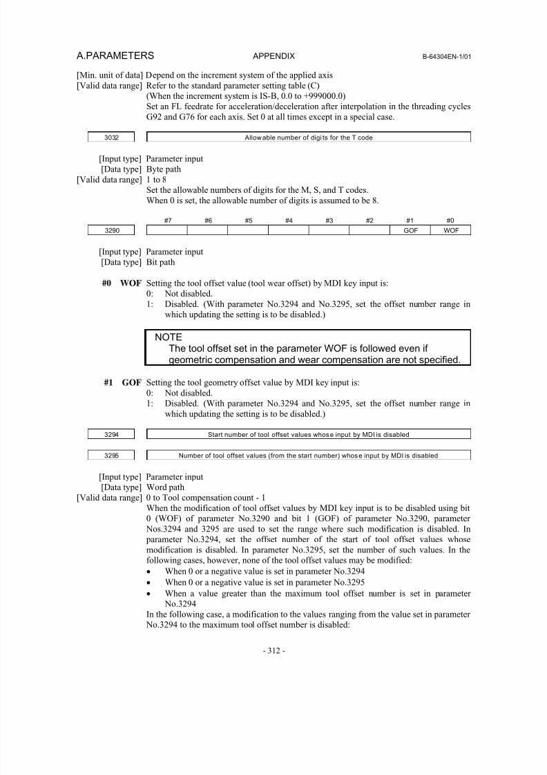
8/16/2019 Manual Operacion para FANUC
http://slidepdf.com/reader/full/manual-operacion-para-fanuc 330/435
A.PARAMETERS APPENDIX B-64304EN-1/01
- 312 -
[Min. unit of data] Depend on the increment system of the applied axis
[Valid data range] Refer to the standard parameter setting table (C)
(When the increment system is IS-B, 0.0 to +999000.0)
Set an FL feedrate for acceleration/deceleration after interpolation in the threading cycles
G92 and G76 for each axis. Set 0 at all times except in a special case.
3032 Allow able number of digi ts for the T code
[Input type] Parameter input
[Data type] Byte path
[Valid data range] 1 to 8
Set the allowable numbers of digits for the M, S, and T codes.
When 0 is set, the allowable number of digits is assumed to be 8.
#7 #6 #5 #4 #3 #2 #1 #0
3290 GOF WOF
[Input type] Parameter input
[Data type] Bit path
#0 WOF Setting the tool offset value (tool wear offset) by MDI key input is:
0: Not disabled.
1: Disabled. (With parameter No.3294 and No.3295, set the offset number range in
which updating the setting is to be disabled.)
NOTEThe tool offset set in the parameter WOF is followed even ifgeometric compensation and wear compensation are not specified.
#1 GOF Setting the tool geometry offset value by MDI key input is:
0: Not disabled.
1: Disabled. (With parameter No.3294 and No.3295, set the offset number range in
which updating the setting is to be disabled.)
3294 Start number of tool offset values whose input by MDI is disabled
3295 Number of tool offset values (from the start number) whose input by MDI is disabled
[Input type] Parameter input
[Data type] Word path[Valid data range] 0 to Tool compensation count - 1
When the modification of tool offset values by MDI key input is to be disabled using bit
0 (WOF) of parameter No.3290 and bit 1 (GOF) of parameter No.3290, parameter
Nos.3294 and 3295 are used to set the range where such modification is disabled. In
parameter No.3294, set the offset number of the start of tool offset values whose
modification is disabled. In parameter No.3295, set the number of such values. In the
following cases, however, none of the tool offset values may be modified:
• When 0 or a negative value is set in parameter No.3294
• When 0 or a negative value is set in parameter No.3295
• When a value greater than the maximum tool offset number is set in parameter
No.3294
In the following case, a modification to the values ranging from the value set in parameter
No.3294 to the maximum tool offset number is disabled:
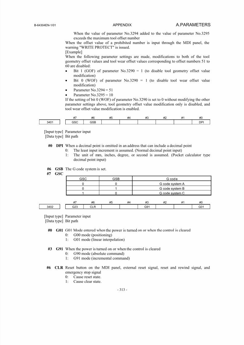
8/16/2019 Manual Operacion para FANUC
http://slidepdf.com/reader/full/manual-operacion-para-fanuc 331/435
B-64304EN-1/01 APPENDIX A.PARAMETERS
- 313 -
When the value of parameter No.3294 added to the value of parameter No.3295
exceeds the maximum tool offset number
When the offset value of a prohibited number is input through the MDI panel, the
warning "WRITE PROTECT" is issued.
[Example]
When the following parameter settings are made, modifications to both of the tool
geometry offset values and tool wear offset values corresponding to offset numbers 51 to
60 are disabled:
• Bit 1 (GOF) of parameter No.3290 = 1 (to disable tool geometry offset value
modification)
• Bit 0 (WOF) of parameter No.3290 = 1 (to disable tool wear offset value
modification)
• Parameter No.3294 = 51
• Parameter No.3295 = 10
If the setting of bit 0 (WOF) of parameter No.3290 is set to 0 without modifying the other
parameter settings above, tool geometry offset value modification only is disabled, and
tool wear offset value modification is enabled.
#7 #6 #5 #4 #3 #2 #1 #0
3401 GSC GSB DPI
[Input type] Parameter input
[Data type] Bit path
#0 DPI When a decimal point is omitted in an address that can include a decimal point
0: The least input increment is assumed. (Normal decimal point input)
1: The unit of mm, inches, degree, or second is assumed. (Pocket calculator type
decimal point input)
#6 GSB The G code system is set.
#7 GSC
GSC GSB G code
0 0 G code system A
0 1 G code system B
1 0 G code system C
#7 #6 #5 #4 #3 #2 #1 #0
3402 G23 CLR G91 G01
[Input type] Parameter input[Data type] Bit path
#0 G01 G01 Mode entered when the power is turned on or when the control is cleared
0: G00 mode (positioning)
1: G01 mode (linear interpolation)
#3 G91 When the power is turned on or when the control is cleared
0: G90 mode (absolute command)
1: G91 mode (incremental command)
#6 CLR Reset button on the MDI panel, external reset signal, reset and rewind signal, and
emergency stop signal0: Cause reset state.
1: Cause clear state.
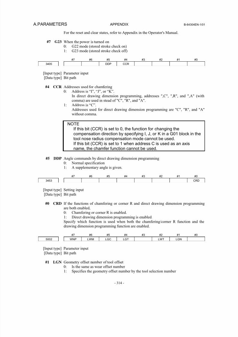
8/16/2019 Manual Operacion para FANUC
http://slidepdf.com/reader/full/manual-operacion-para-fanuc 332/435
A.PARAMETERS APPENDIX B-64304EN-1/01
- 314 -
For the reset and clear states, refer to Appendix in the Operator's Manual.
#7 G23 When the power is turned on
0: G22 mode (stored stroke check on)
1: G23 mode (stored stroke check off)
#7 #6 #5 #4 #3 #2 #1 #0
3405 DDP CCR
[Input type] Parameter input
[Data type] Bit path
#4 CCR Addresses used for chamfering
0: Address is “I”, “J”, or “K”.
In direct drawing dimension programming, addresses ",C", ",R", and ",A" (with
comma) are used in stead of "C", "R", and "A".
1: Address is “C”.Addresses used for direct drawing dimension programming are "C", "R", and "A"
without comma.
NOTEIf this bit (CCR) is set to 0, the function for changing thecompensation direction by specifying I, J, or K in a G01 block in thetool nose radius compensation mode cannot be used.If this bit (CCR) is set to 1 when address C is used as an axisname, the chamfer function cannot be used.
#5 DDP Angle commands by direct drawing dimension programming0: Normal specification
1: A supplementary angle is given.
#7 #6 #5 #4 #3 #2 #1 #0
3453 CRD
[Input type] Setting input
[Data type] Bit path
#0 CRD If the functions of chamfering or corner R and direct drawing dimension programming
are both enabled,
0: Chamfering or corner R is enabled.1: Direct drawing dimension programming is enabled.
Specify which function is used when both the chamfering/corner R function and the
drawing dimension programming function are enabled.
#7 #6 #5 #4 #3 #2 #1 #0
5002 WNP LWM LGC LGT LWT LGN
[Input type] Parameter input
[Data type] Bit path
#1 LGN Geometry offset number of tool offset
0: Is the same as wear offset number
1: Specifies the geometry offset number by the tool selection number
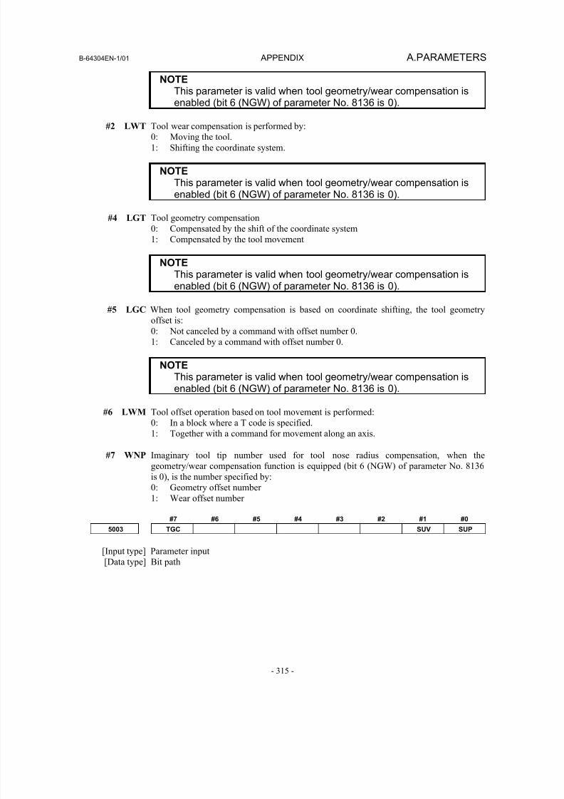
8/16/2019 Manual Operacion para FANUC
http://slidepdf.com/reader/full/manual-operacion-para-fanuc 333/435
B-64304EN-1/01 APPENDIX A.PARAMETERS
- 315 -
NOTEThis parameter is valid when tool geometry/wear compensation isenabled (bit 6 (NGW) of parameter No. 8136 is 0).
#2 LWT Tool wear compensation is performed by:0: Moving the tool.
1: Shifting the coordinate system.
NOTEThis parameter is valid when tool geometry/wear compensation isenabled (bit 6 (NGW) of parameter No. 8136 is 0).
#4 LGT Tool geometry compensation
0: Compensated by the shift of the coordinate system
1: Compensated by the tool movement
NOTEThis parameter is valid when tool geometry/wear compensation isenabled (bit 6 (NGW) of parameter No. 8136 is 0).
#5 LGC When tool geometry compensation is based on coordinate shifting, the tool geometry
offset is:
0: Not canceled by a command with offset number 0.
1: Canceled by a command with offset number 0.
NOTE
This parameter is valid when tool geometry/wear compensation isenabled (bit 6 (NGW) of parameter No. 8136 is 0).
#6 LWM Tool offset operation based on tool movement is performed:
0: In a block where a T code is specified.
1: Together with a command for movement along an axis.
#7 WNP Imaginary tool tip number used for tool nose radius compensation, when the
geometry/wear compensation function is equipped (bit 6 (NGW) of parameter No. 8136
is 0), is the number specified by:
0: Geometry offset number
1: Wear offset number
#7 #6 #5 #4 #3 #2 #1 #0
5003 TGC SUV SUP
[Input type] Parameter input
[Data type] Bit path
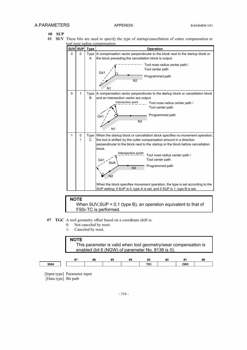
8/16/2019 Manual Operacion para FANUC
http://slidepdf.com/reader/full/manual-operacion-para-fanuc 334/435
A.PARAMETERS APPENDIX B-64304EN-1/01
- 316 -
#0 SUP
#1 SUV These bits are used to specify the type of startup/cancellation of cutter compensation or
tool nose radius compensation.
SUV SUP Type Operation
0 0 Type A
A compensation vector perpendicular to the block next to the startup block orthe block preceding the cancellation block is output.
0 1 Type
B
A compensation vector perpendicular to the startup block or cancellation block
and an intersection vector are output.
1 0
1
Type
C
When the startup block or cancellation block specifies no movement operation,
the tool is shifted by the cutter compensation amount in a direction
perpendicular to the block next to the startup or the block before cancellation
block.
When the block specifies movement operation, the type is set according to the
SUP setting; if SUP is 0, type A is set, and if SUP is 1, type B is set.
NOTEWhen SUV,SUP = 0,1 (type B), an operation equivalent to that ofFS0i-TC is performed.
#7 TGC A tool geometry offset based on a coordinate shift is:0: Not canceled by reset.
1: Canceled by reset.
NOTEThis parameter is valid when tool geometry/wear compensation isenabled (bit 6 (NGW) of parameter No. 8136 is 0).
#7 #6 #5 #4 #3 #2 #1 #0
5004 TS1 ORC
[Input type] Parameter input[Data type] Bit path
Tool nose radius center path /
Tool center path
Programmed path
N1
N2
G41
N2
N3
Intersection point
ShiftG41
Tool nose radius center path /
Tool center path
N1
N2
Intersection point
G41 Programmed path
Programmed path
Tool nose radius center path /
Tool center path
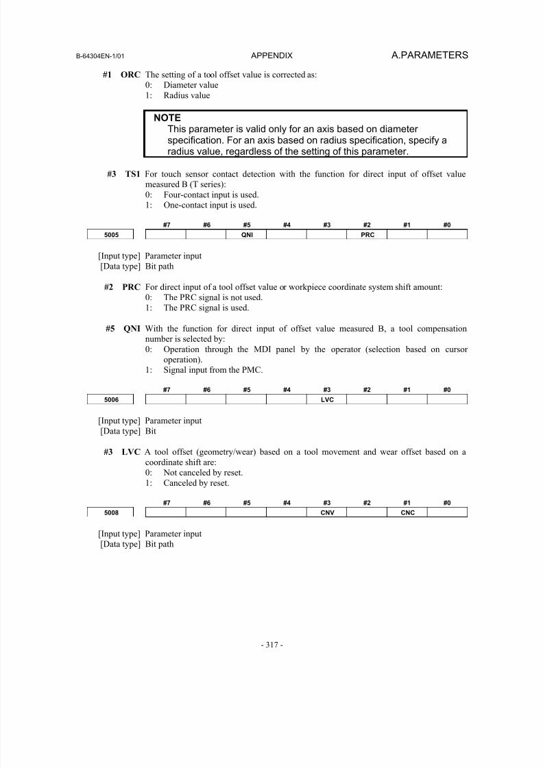
8/16/2019 Manual Operacion para FANUC
http://slidepdf.com/reader/full/manual-operacion-para-fanuc 335/435
B-64304EN-1/01 APPENDIX A.PARAMETERS
- 317 -
#1 ORC The setting of a tool offset value is corrected as:
0: Diameter value
1: Radius value
NOTEThis parameter is valid only for an axis based on diameterspecification. For an axis based on radius specification, specify aradius value, regardless of the setting of this parameter.
#3 TS1 For touch sensor contact detection with the function for direct input of offset value
measured B (T series):
0: Four-contact input is used.
1: One-contact input is used.
#7 #6 #5 #4 #3 #2 #1 #0
5005 QNI PRC
[Input type] Parameter input
[Data type] Bit path
#2 PRC For direct input of a tool offset value or workpiece coordinate system shift amount:
0: The PRC signal is not used.
1: The PRC signal is used.
#5 QNI With the function for direct input of offset value measured B, a tool compensation
number is selected by:
0: Operation through the MDI panel by the operator (selection based on cursor
operation).1: Signal input from the PMC.
#7 #6 #5 #4 #3 #2 #1 #0
5006 LVC
[Input type] Parameter input
[Data type] Bit
#3 LVC A tool offset (geometry/wear) based on a tool movement and wear offset based on a
coordinate shift are:
0: Not canceled by reset.
1: Canceled by reset.
#7 #6 #5 #4 #3 #2 #1 #0
5008 CNV CNC
[Input type] Parameter input
[Data type] Bit path

8/16/2019 Manual Operacion para FANUC
http://slidepdf.com/reader/full/manual-operacion-para-fanuc 336/435
A.PARAMETERS APPENDIX B-64304EN-1/01
- 318 -
#1 CNC
#3 CNV These bits are used to select an interference check method in the cutter compensation or
tool nose radius compensation mode.
CNV CNC Operation
0 0 Interference check is enabled. The direction and the angle of an arc are checked.0 1 Interference check is enabled. Only the angle of an arc is checked.
1 - Interference check is disabled.
For the operation taken when the interference check shows the occurrence of an reference
(overcutting) , see the description of bit 5 (CAV) of parameter No. 19607.
NOTEChecking of only the direction cannot be set.
#7 #6 #5 #4 #3 #2 #1 #0
5009 TSD GSC
[Input type] Parameter input
[Data type] Bit path
NOTEWhen at least one of these parameters is set, the power must beturned off before operation is continued.
#0 GSC When the function for direct input of offset value measured B (T series) is used, an offset
write input signal is input from:
0: Machine side
1: PMC side
When the interlock function for each axis direction is enabled (when bit 3 (DIT) of
parameter No. 3003 is set to 0), switching can also be made between input from the
machine side and input from PMC side for the interlock function for each axis direction.
#4 TSD In the function for direct input of offset value measured B (T series), the movement
direction determination specifications:
0: Do not apply.
1: Apply.
This parameter is valid when four-contact input is used (bit 3 (TS1) of parameter No.
5004 is set to 0).
5010 Limit for ignoring the small movement resulting from cutter or tool nose radius compensation
[Input type] Setting input
[Data type] Real path
[Unit of data] mm, inch (input unit)
[Min. unit of data] Depend on the increment system of the reference axis
[Valid data range] 9 digit of minimum unit of data (refer to standard parameter setting table (A))
(When the increment system is IS-B, -999999.999 to +999999.999)
When the tool moves around a corner in cutter compensation or tool nose radius
compensation mode, the limit for ignoring the small travel amount resulting from
compensation is set. This limit eliminates the interruption of buffering caused by the
small travel amount generated at the corner and any change in feedrate due to the
interruption.
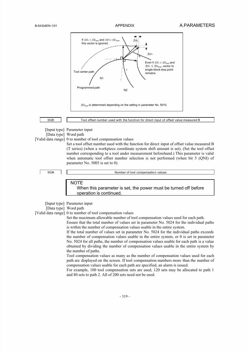
8/16/2019 Manual Operacion para FANUC
http://slidepdf.com/reader/full/manual-operacion-para-fanuc 337/435
B-64304EN-1/01 APPENDIX A.PARAMETERS
- 319 -
Even if ΔVx ≤ ΔVlimit and
ΔVY ≤ ΔVlimit, vector to
single-block stop point
remains.Tool center path
Programmed path
If ΔVx ≤ ΔVlimit and ΔVY≤ ΔVlimit,
this vector is ignored.
S Δ
VY
ΔVx
r
r
N1
N2
ΔVlimit is determined depending on the setting in parameter No. 5010.
5020 Tool offset number used with the functi on for direct input of offset value measured B
[Input type] Parameter input
[Data type] Word path
[Valid data range] 0 to number of tool compensation values
Set a tool offset number used with the function for direct input of offset value measured B
(T series) (when a workpiece coordinate system shift amount is set). (Set the tool offset
number corresponding to a tool under measurement beforehand.) This parameter is valid
when automatic tool offset number selection is not performed (when bit 5 (QNI) of
parameter No. 5005 is set to 0).
5024 Number of tool compensation values
NOTEWhen this parameter is set, the power must be turned off beforeoperation is continued.
[Input type] Parameter input
[Data type] Word path
[Valid data range] 0 to number of tool compensation values
Set the maximum allowable number of tool compensation values used for each path.
Ensure that the total number of values set in parameter No. 5024 for the individual pathsis within the number of compensation values usable in the entire system.
If the total number of values set in parameter No. 5024 for the individual paths exceeds
the number of compensation values usable in the entire system, or 0 is set in parameter
No. 5024 for all paths, the number of compensation values usable for each path is a value
obtained by dividing the number of compensation values usable in the entire system by
the number of paths.
Tool compensation values as many as the number of compensation values used for each
path are displayed on the screen. If tool compensation numbers more than the number of
compensation values usable for each path are specified, an alarm is issued.
For example, 100 tool compensation sets are used, 120 sets may be allocated to path 1
and 80 sets to path 2. All of 200 sets need not be used.
8/16/2019 Manual Operacion para FANUC
http://slidepdf.com/reader/full/manual-operacion-para-fanuc 338/435
A.PARAMETERS APPENDIX B-64304EN-1/01
- 320 -
5028 Number of digit s of an offset number used with a T code command
[Input type] Parameter input
[Data type] Byte path
[Valid data range] 0 to 3Specify the number of digits of a T code portion that is used for a tool offset number
(wear offset number when the tool geometry/wear compensation function is used).
When 0 is set, the number of digits is determined by the number of tool compensation
values.
When the number of tool compensation values is 1 to 9: Lower 1 digit
When the number of tool compensation values is 10 to 99: Lower 2 digits
When the number of tool compensation values is 100 to 200: Lower 3 digits
Example :
When an offset number is specified using the lower 2 digits of a T code, set 2 in
parameter No. 5028.
Txxxxxx yy
xxxxxx : Tool selectionyy : Tool offset number
NOTE A value longer than the setting of parameter No. 3032 (allowablenumber of digits of a T code) cannot be set.
5029 Number of tool compensation value memories common to paths
NOTEWhen this parameter is set, the power must be turned off before
operation is continued.
[Input type] Parameter input
[Data type] Word
[Valid data range] 0 to number of tool compensation values
When using memories common to paths, set the number of common tool compensation
values in this parameter.
Ensure that the setting of this parameter does not exceed the number of tool compensation
values set for each path (parameter No. 5024).
[Example 1]
When parameter No. 5029 = 10, parameter No. 5024 (path 1) = 15, and parameter
No. 5024 (path 2) = 30 in a 2-path system, tool compensation numbers 1 to 10 of all paths are made common.
[Example 2]
When parameter No. 5029 = 20 and the other conditions are the same as for
Example 1, tool compensation numbers 1 to 15 are made common.
NOTE1 Ensure that the setting of parameter No. 5029 does not exceed the
number of tool compensation values for each path (parameter No.5024). If the setting of parameter No. 5029 exceeds the number ofcompensation values of a path, the least of the numbers ofcompensation values in all paths is made common.
2 When 0 or a negative value is set, memories common to paths arenot used.
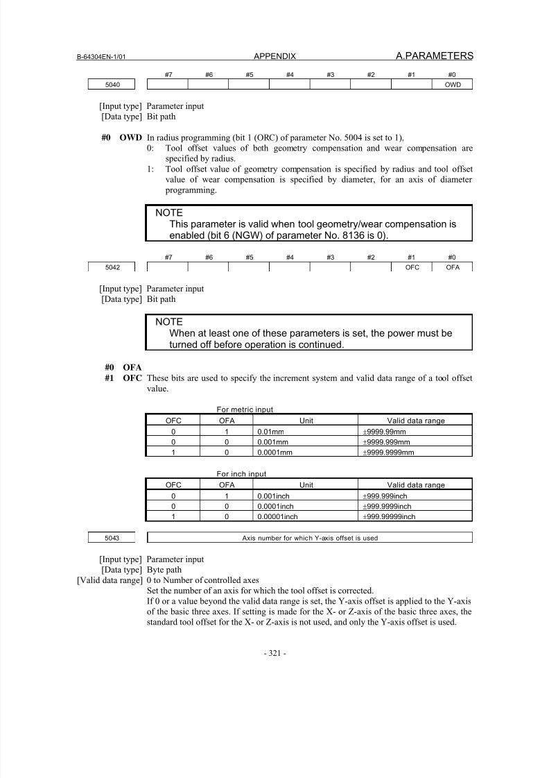
8/16/2019 Manual Operacion para FANUC
http://slidepdf.com/reader/full/manual-operacion-para-fanuc 339/435
B-64304EN-1/01 APPENDIX A.PARAMETERS
- 321 -
#7 #6 #5 #4 #3 #2 #1 #0
5040 OWD
[Input type] Parameter input
[Data type] Bit path
#0 OWD In radius programming (bit 1 (ORC) of parameter No. 5004 is set to 1),
0: Tool offset values of both geometry compensation and wear compensation are
specified by radius.
1: Tool offset value of geometry compensation is specified by radius and tool offset
value of wear compensation is specified by diameter, for an axis of diameter
programming.
NOTEThis parameter is valid when tool geometry/wear compensation isenabled (bit 6 (NGW) of parameter No. 8136 is 0).
#7 #6 #5 #4 #3 #2 #1 #0
5042 OFC OFA
[Input type] Parameter input
[Data type] Bit path
NOTEWhen at least one of these parameters is set, the power must beturned off before operation is continued.
#0 OFA #1 OFC These bits are used to specify the increment system and valid data range of a tool offset
value.
For metric input
OFC OFA Unit Valid data range
0 1 0.01mm ±9999.99mm
0 0 0.001mm ±9999.999mm
1 0 0.0001mm ±9999.9999mm
For inch input
OFC
OFA Unit
Valid data range
0 1 0.001inch ±999.999inch
0 0 0.0001inch ±999.9999inch
1 0 0.00001inch ±999.99999inch
5043 Axis number for which Y-axis offset is used
[Input type] Parameter input
[Data type] Byte path
[Valid data range] 0 to Number of controlled axes
Set the number of an axis for which the tool offset is corrected.
If 0 or a value beyond the valid data range is set, the Y-axis offset is applied to the Y-axis
of the basic three axes. If setting is made for the X- or Z-axis of the basic three axes, thestandard tool offset for the X- or Z-axis is not used, and only the Y-axis offset is used.
8/16/2019 Manual Operacion para FANUC
http://slidepdf.com/reader/full/manual-operacion-para-fanuc 340/435
A.PARAMETERS APPENDIX B-64304EN-1/01
- 322 -
#7 #6 #5 #4 #3 #2 #1 #0
5101 RTR FXY
[Input type] Parameter input
[Data type] Bit path
#0 FXY The drilling axis in the drilling canned cycle, or cutting axis in the grinding canned cycle
is:
0: In case of the Drilling canned cycle:
Z-axis at all times.
In case of the Grinding canned cycle:
Z-axis at all times.
1: Axis selected by the program
NOTE1 In the case of the T series, this parameter is valid only for the
drilling canned cycle in the Series 10/11 format.2 When this parameter is 1, the drilling axis determined by plane
selection (G17/G18/G19) in the drilling canned cycle in the T series10/11 format. Therefore, the Y-axis is required to specifyG17/G19.
#2 RTR G83 and G87
0: Specify a high-speed peck drilling cycle
1: Specify a peck drilling cycle
#7 #6 #5 #4 #3 #2 #1 #0
5102 RDI RAB F0C QSR
[Input type] Parameter input
[Data type] Bit path
#2 QSR Before a multiple repetitive canned cycle (G70 to G73) (T series) is started, a check to see
if the program contains a block that has the sequence number specified in address Q is:
0: Not made.
1: Made.
When 1 is set in this parameter and the sequence number specified in address Q is not
found, the alarm (PS0063) is issued and the canned cycle is not executed.
#3 F0C When the Series 10/11 format is used (with bit 1 (FCV) of parameter No.0001 set to 1), a
canned drilling cycle is specified using :
0: Series 10/11 format
1: Series 0 format. However, the number of repetitions is specified using address L.
#6 RAB When a canned drilling cycle using the Series 10/11 format is specified (with bit 1 (FCV)
of parameter No. 0001 set to 1 and bit 3 (F0C) of parameter No. 5102 set to 0), address R
specifies:
0: Increment command.
1: Absolute command with G code system A. With G code system B or C, G90 and
G91 are followed.
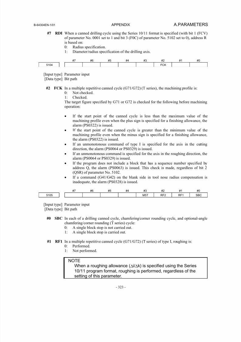
8/16/2019 Manual Operacion para FANUC
http://slidepdf.com/reader/full/manual-operacion-para-fanuc 341/435
B-64304EN-1/01 APPENDIX A.PARAMETERS
- 323 -
#7 RDI When a canned drilling cycle using the Series 10/11 format is specified (with bit 1 (FCV)
of parameter No. 0001 set to 1 and bit 3 (F0C) of parameter No. 5102 set to 0), address R
is based on:
0: Radius specification.
1: Diameter/radius specification of the drilling axis.
#7 #6 #5 #4 #3 #2 #1 #0
5104 FCK
[Input type] Parameter input
[Data type] Bit path
#2 FCK In a multiple repetitive canned cycle (G71/G72) (T series), the machining profile is:
0: Not checked.
1: Checked.
The target figure specified by G71 or G72 is checked for the following before machining
operation:
• If the start point of the canned cycle is less than the maximum value of the
machining profile even when the plus sign is specified for a finishing allowance, the
alarm (PS0322) is issued.
• If the start point of the canned cycle is greater than the minimum value of the
machining profile even when the minus sign is specified for a finishing allowance,
the alarm (PS0322) is issued.
• If an unmonotonous command of type I is specified for the axis in the cutting
direction, the alarm (PS0064 or PS0329) is issued.
• If an unmonotonous command is specified for the axis in the roughing direction, the
alarm (PS0064 or PS0329) is issued.
• If the program does not include a block that has a sequence number specified by
address Q, the alarm (PS0063) is issued. This check is made, regardless of bit 2
(QSR) of parameter No. 5102.
• If a command (G41/G42) on the blank side in tool nose radius compensation is
inadequate, the alarm (PS0328) is issued.
#7 #6 #5 #4 #3 #2 #1 #0
5105 M5T RF2 RF1 SBC
[Input type] Parameter input
[Data type] Bit path
#0 SBC In each of a drilling canned cycle, chamfering/corner rounding cycle, and optional-angle
chamfering/corner rounding (T series) cycle:
0: A single block stop is not carried out.
1: A single block stop is carried out.
#1 RF1 In a multiple repetitive canned cycle (G71/G72) (T series) of type I, roughing is:
0: Performed.
1: Not performed.
NOTEWhen a roughing allowance (Δi/Δk) is specified using the Series
10/11 program format, roughing is performed, regardless of thesetting of this parameter.
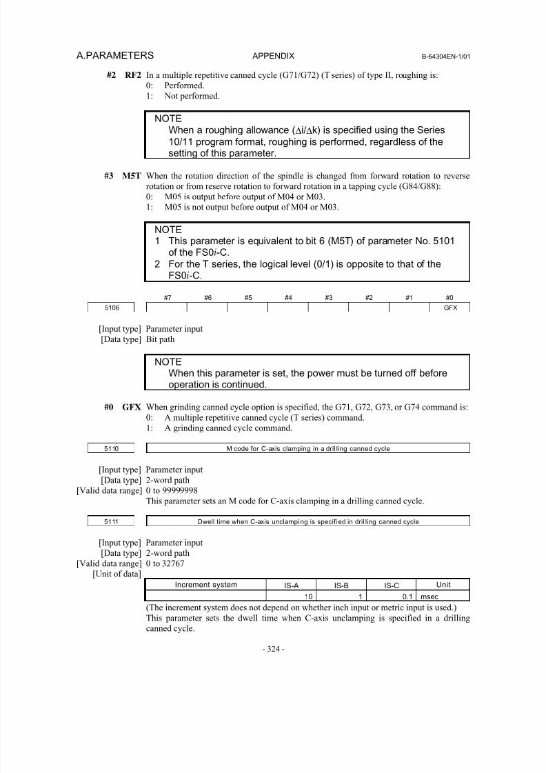
8/16/2019 Manual Operacion para FANUC
http://slidepdf.com/reader/full/manual-operacion-para-fanuc 342/435
A.PARAMETERS APPENDIX B-64304EN-1/01
- 324 -
#2 RF2 In a multiple repetitive canned cycle (G71/G72) (T series) of type II, roughing is:
0: Performed.
1: Not performed.
NOTEWhen a roughing allowance (Δi/Δk) is specified using the Series
10/11 program format, roughing is performed, regardless of thesetting of this parameter.
#3 M5T When the rotation direction of the spindle is changed from forward rotation to reverse
rotation or from reserve rotation to forward rotation in a tapping cycle (G84/G88):
0: M05 is output before output of M04 or M03.
1: M05 is not output before output of M04 or M03.
NOTE
1 This parameter is equivalent to bit 6 (M5T) of parameter No. 5101of the FS0i-C.
2 For the T series, the logical level (0/1) is opposite to that of theFS0i-C.
#7 #6 #5 #4 #3 #2 #1 #0
5106 GFX
[Input type] Parameter input
[Data type] Bit path
NOTEWhen this parameter is set, the power must be turned off beforeoperation is continued.
#0 GFX When grinding canned cycle option is specified, the G71, G72, G73, or G74 command is:
0: A multiple repetitive canned cycle (T series) command.
1: A grinding canned cycle command.
5110 M code for C-axis clamping in a dril ling canned cycle
[Input type] Parameter input
[Data type] 2-word path
[Valid data range] 0 to 99999998
This parameter sets an M code for C-axis clamping in a drilling canned cycle.
5111 Dwell time when C-axis unclamping is specifi ed in dril ling canned cycle
[Input type] Parameter input
[Data type] 2-word path
[Valid data range] 0 to 32767
[Unit of data]
Increment system IS-A IS-B IS-C Unit
10 1 0.1 msec
(The increment system does not depend on whether inch input or metric input is used.)This parameter sets the dwell time when C-axis unclamping is specified in a drilling
canned cycle.
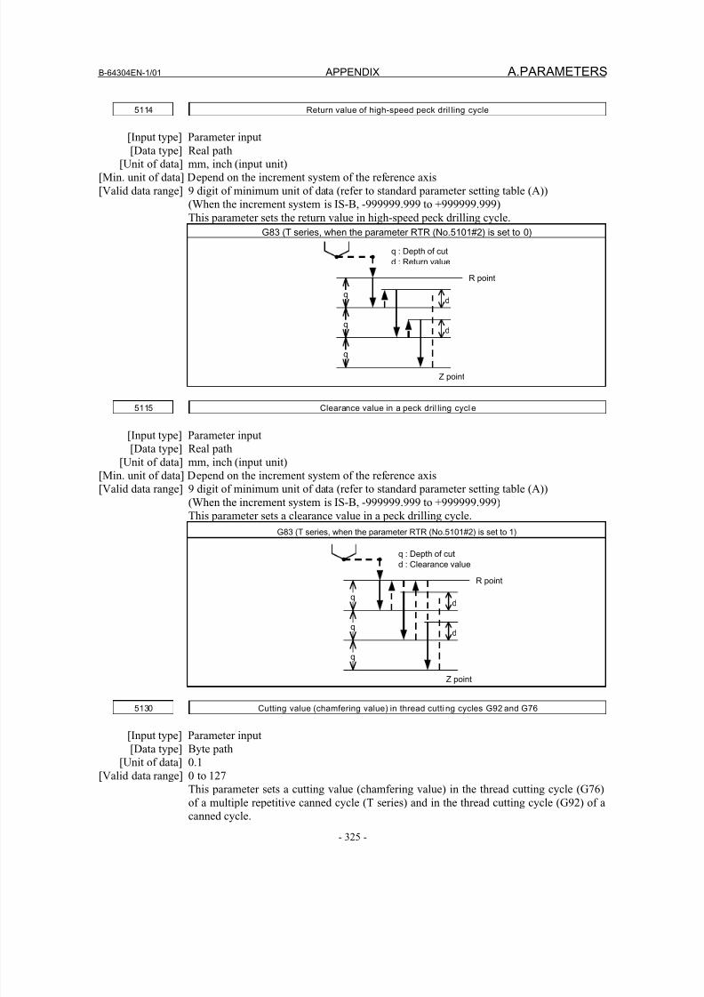
8/16/2019 Manual Operacion para FANUC
http://slidepdf.com/reader/full/manual-operacion-para-fanuc 343/435
B-64304EN-1/01 APPENDIX A.PARAMETERS
- 325 -
5114 Return value of high-speed peck dril ling cycle
[Input type] Parameter input
[Data type] Real path[Unit of data] mm, inch (input unit)
[Min. unit of data] Depend on the increment system of the reference axis
[Valid data range] 9 digit of minimum unit of data (refer to standard parameter setting table (A))
(When the increment system is IS-B, -999999.999 to +999999.999)
This parameter sets the return value in high-speed peck drilling cycle.
G83 (T series, when the parameter RTR (No.5101#2) is set to 0)
5115 Clearance value in a peck dril ling cycle
[Input type] Parameter input
[Data type] Real path
[Unit of data] mm, inch (input unit)
[Min. unit of data] Depend on the increment system of the reference axis
[Valid data range] 9 digit of minimum unit of data (refer to standard parameter setting table (A))
(When the increment system is IS-B, -999999.999 to +999999.999)
This parameter sets a clearance value in a peck drilling cycle.
G83 (T series, when the parameter RTR (No.5101#2) is set to 1)
5130 Cutting value (chamfering value) in thread cutting cycles G92 and G76
[Input type] Parameter input
[Data type] Byte path
[Unit of data] 0.1
[Valid data range] 0 to 127
This parameter sets a cutting value (chamfering value) in the thread cutting cycle (G76)
of a multiple repetitive canned cycle (T series) and in the thread cutting cycle (G92) of a
canned cycle.
q
q
q
d
d
q : Depth of cut
d : Return value
R point
Z point
q
q
q
d
d
q : Depth of cut
d : Clearance value
R point
Z point
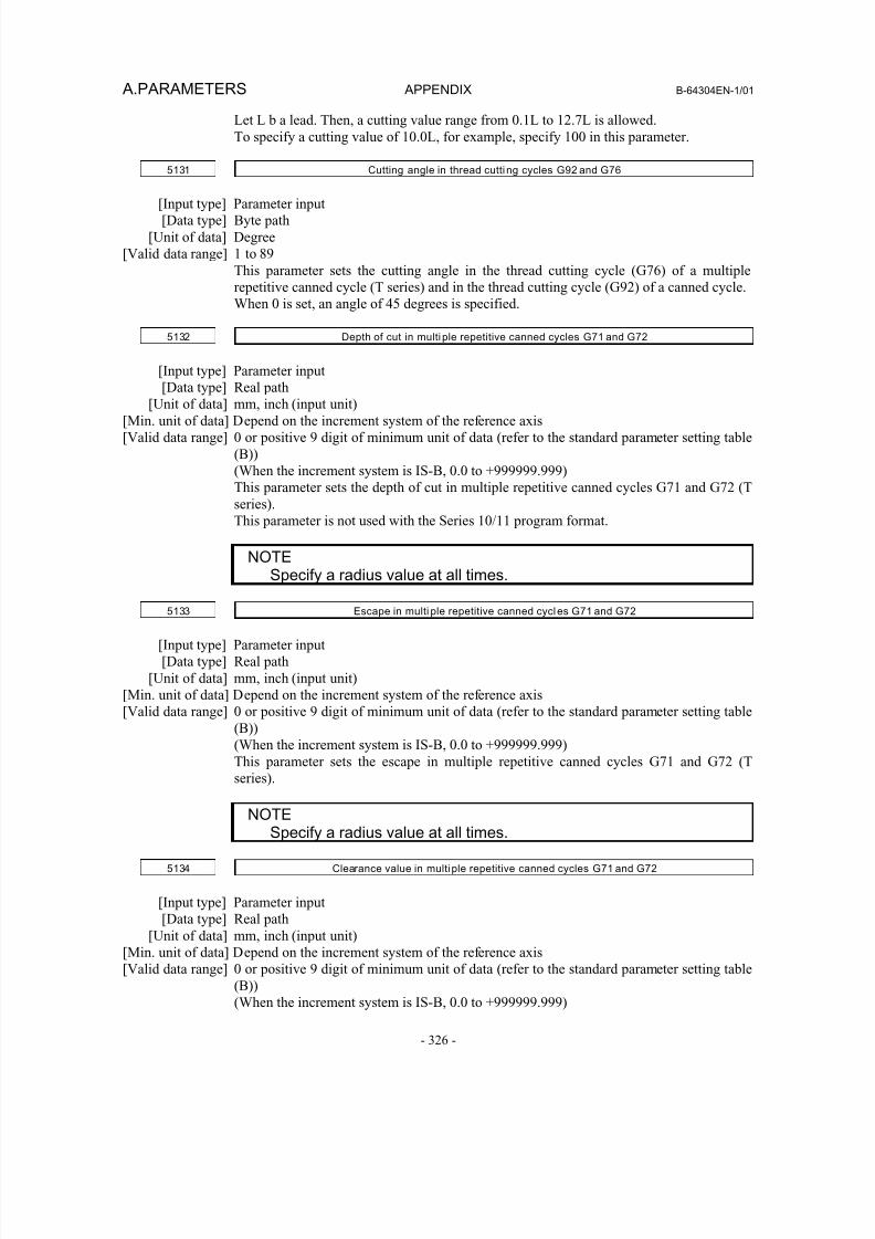
8/16/2019 Manual Operacion para FANUC
http://slidepdf.com/reader/full/manual-operacion-para-fanuc 344/435
A.PARAMETERS APPENDIX B-64304EN-1/01
- 326 -
Let L b a lead. Then, a cutting value range from 0.1L to 12.7L is allowed.
To specify a cutting value of 10.0L, for example, specify 100 in this parameter.
5131 Cutting angle in thread cutting cycles G92 and G76
[Input type] Parameter input
[Data type] Byte path
[Unit of data] Degree
[Valid data range] 1 to 89
This parameter sets the cutting angle in the thread cutting cycle (G76) of a multiple
repetitive canned cycle (T series) and in the thread cutting cycle (G92) of a canned cycle.
When 0 is set, an angle of 45 degrees is specified.
5132 Depth of cut in multiple repetitive canned cycles G71 and G72
[Input type] Parameter input
[Data type] Real path[Unit of data] mm, inch (input unit)
[Min. unit of data] Depend on the increment system of the reference axis
[Valid data range] 0 or positive 9 digit of minimum unit of data (refer to the standard parameter setting table
(B))
(When the increment system is IS-B, 0.0 to +999999.999)
This parameter sets the depth of cut in multiple repetitive canned cycles G71 and G72 (T
series).
This parameter is not used with the Series 10/11 program format.
NOTESpecify a radius value at all times.
5133 Escape in multi ple repetitive canned cycles G71 and G72
[Input type] Parameter input
[Data type] Real path
[Unit of data] mm, inch (input unit)
[Min. unit of data] Depend on the increment system of the reference axis
[Valid data range] 0 or positive 9 digit of minimum unit of data (refer to the standard parameter setting table
(B))
(When the increment system is IS-B, 0.0 to +999999.999)
This parameter sets the escape in multiple repetitive canned cycles G71 and G72 (T
series).
NOTESpecify a radius value at all times.
5134 Clearance value in multiple repetitive canned cycles G71 and G72
[Input type] Parameter input
[Data type] Real path
[Unit of data] mm, inch (input unit)
[Min. unit of data] Depend on the increment system of the reference axis
[Valid data range] 0 or positive 9 digit of minimum unit of data (refer to the standard parameter setting table(B))
(When the increment system is IS-B, 0.0 to +999999.999)
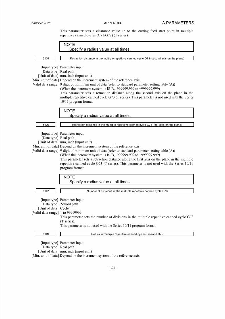
8/16/2019 Manual Operacion para FANUC
http://slidepdf.com/reader/full/manual-operacion-para-fanuc 345/435
B-64304EN-1/01 APPENDIX A.PARAMETERS
- 327 -
This parameter sets a clearance value up to the cutting feed start point in multiple
repetitive canned cycles (G71/G72) (T series).
NOTE
Specify a radius value at all times.
5135 Retraction distance in the multiple repetitive canned cycle G73 (second axis on the plane)
[Input type] Parameter input
[Data type] Real path
[Unit of data] mm, inch (input unit)
[Min. unit of data] Depend on the increment system of the reference axis
[Valid data range] 9 digit of minimum unit of data (refer to standard parameter setting table (A))
(When the increment system is IS-B, -999999.999 to +999999.999)
This parameter sets a retraction distance along the second axis on the plane in the
multiple repetitive canned cycle G73 (T series). This parameter is not used with the Series
10/11 program format.
NOTESpecify a radius value at all times.
5136 Retraction distance in the multiple repetitive canned cycle G73 (first axis on the plane)
[Input type] Parameter input
[Data type] Real path
[Unit of data] mm, inch (input unit)
[Min. unit of data] Depend on the increment system of the reference axis
[Valid data range] 9 digit of minimum unit of data (refer to standard parameter setting table (A))(When the increment system is IS-B, -999999.999 to +999999.999)
This parameter sets a retraction distance along the first axis on the plane in the multiple
repetitive canned cycle G73 (T series). This parameter is not used with the Series 10/11
program format.
NOTESpecify a radius value at all times.
5137 Number of divis ions in the multiple repetitive canned cycle G73
[Input type] Parameter input[Data type] 2-word path
[Unit of data] Cycle
[Valid data range] 1 to 99999999
This parameter sets the number of divisions in the multiple repetitive canned cycle G73
(T series).
This parameter is not used with the Series 10/11 program format.
5139 Return in multiple repetitive canned cycles G74 and G75
[Input type] Parameter input
[Data type] Real path
[Unit of data] mm, inch (input unit)[Min. unit of data] Depend on the increment system of the reference axis
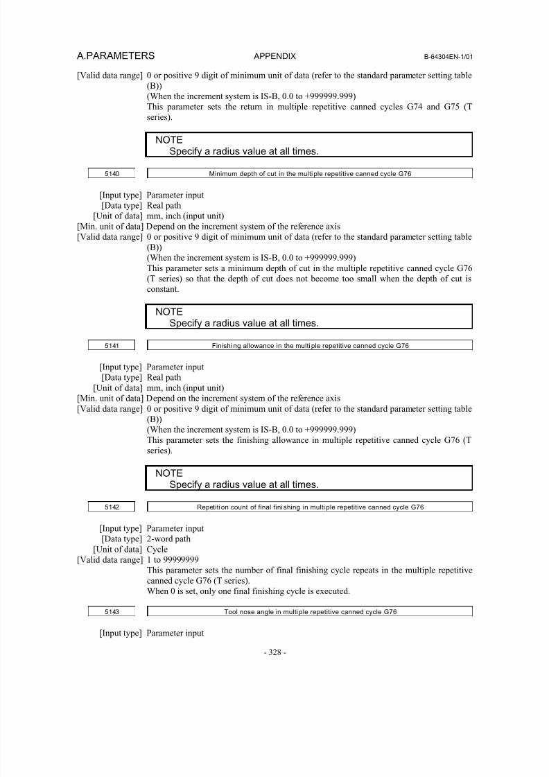
8/16/2019 Manual Operacion para FANUC
http://slidepdf.com/reader/full/manual-operacion-para-fanuc 346/435
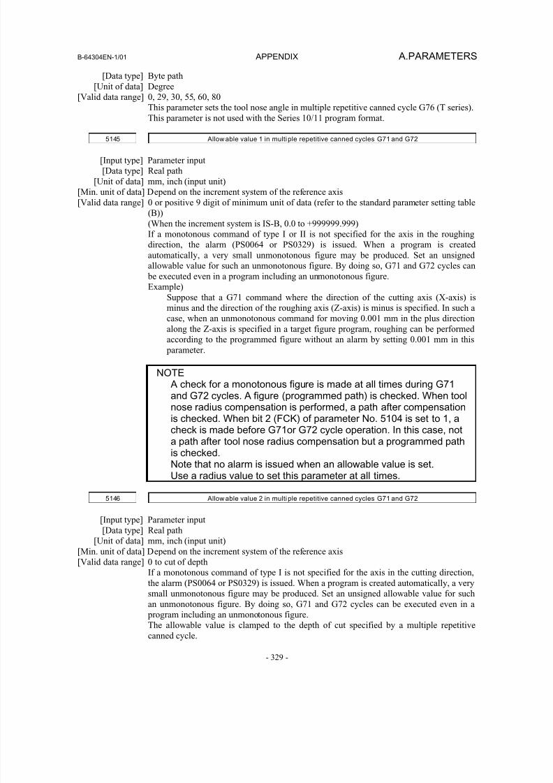
8/16/2019 Manual Operacion para FANUC
http://slidepdf.com/reader/full/manual-operacion-para-fanuc 347/435
B-64304EN-1/01 APPENDIX A.PARAMETERS
- 329 -
[Data type] Byte path
[Unit of data] Degree
[Valid data range] 0, 29, 30, 55, 60, 80
This parameter sets the tool nose angle in multiple repetitive canned cycle G76 (T series).
This parameter is not used with the Series 10/11 program format.
5145 Allow able value 1 in multiple repetitive canned cycles G71 and G72
[Input type] Parameter input
[Data type] Real path
[Unit of data] mm, inch (input unit)
[Min. unit of data] Depend on the increment system of the reference axis
[Valid data range] 0 or positive 9 digit of minimum unit of data (refer to the standard parameter setting table
(B))
(When the increment system is IS-B, 0.0 to +999999.999)
If a monotonous command of type I or II is not specified for the axis in the roughing
direction, the alarm (PS0064 or PS0329) is issued. When a program is createdautomatically, a very small unmonotonous figure may be produced. Set an unsigned
allowable value for such an unmonotonous figure. By doing so, G71 and G72 cycles can
be executed even in a program including an unmonotonous figure.
Example)
Suppose that a G71 command where the direction of the cutting axis (X-axis) is
minus and the direction of the roughing axis (Z-axis) is minus is specified. In such a
case, when an unmonotonous command for moving 0.001 mm in the plus direction
along the Z-axis is specified in a target figure program, roughing can be performed
according to the programmed figure without an alarm by setting 0.001 mm in this
parameter.
NOTE A check for a monotonous figure is made at all times during G71and G72 cycles. A figure (programmed path) is checked. When toolnose radius compensation is performed, a path after compensationis checked. When bit 2 (FCK) of parameter No. 5104 is set to 1, acheck is made before G71or G72 cycle operation. In this case, nota path after tool nose radius compensation but a programmed pathis checked.Note that no alarm is issued when an allowable value is set.Use a radius value to set this parameter at all times.
5146 Allow able value 2 in multiple repetitive canned cycles G71 and G72
[Input type] Parameter input
[Data type] Real path
[Unit of data] mm, inch (input unit)
[Min. unit of data] Depend on the increment system of the reference axis
[Valid data range] 0 to cut of depth
If a monotonous command of type I is not specified for the axis in the cutting direction,
the alarm (PS0064 or PS0329) is issued. When a program is created automatically, a very
small unmonotonous figure may be produced. Set an unsigned allowable value for such
an unmonotonous figure. By doing so, G71 and G72 cycles can be executed even in a
program including an unmonotonous figure.The allowable value is clamped to the depth of cut specified by a multiple repetitive
canned cycle.
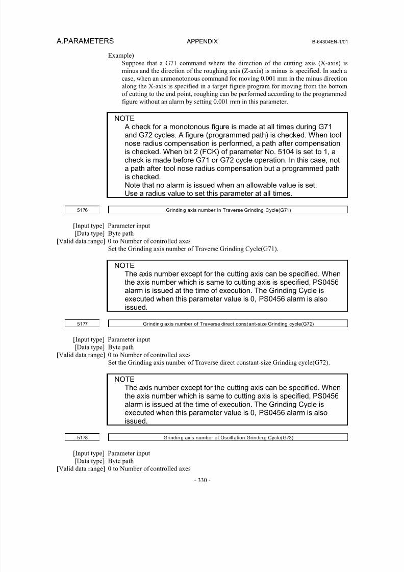
8/16/2019 Manual Operacion para FANUC
http://slidepdf.com/reader/full/manual-operacion-para-fanuc 348/435
A.PARAMETERS APPENDIX B-64304EN-1/01
- 330 -
Example)
Suppose that a G71 command where the direction of the cutting axis (X-axis) is
minus and the direction of the roughing axis (Z-axis) is minus is specified. In such a
case, when an unmonotonous command for moving 0.001 mm in the minus direction
along the X-axis is specified in a target figure program for moving from the bottom
of cutting to the end point, roughing can be performed according to the programmed
figure without an alarm by setting 0.001 mm in this parameter.
NOTE A check for a monotonous figure is made at all times during G71and G72 cycles. A figure (programmed path) is checked. When toolnose radius compensation is performed, a path after compensationis checked. When bit 2 (FCK) of parameter No. 5104 is set to 1, acheck is made before G71 or G72 cycle operation. In this case, nota path after tool nose radius compensation but a programmed path
is checked.Note that no alarm is issued when an allowable value is set.Use a radius value to set this parameter at all times.
5176 Grinding axis number in Traverse Grinding Cycle(G71)
[Input type] Parameter input
[Data type] Byte path
[Valid data range] 0 to Number of controlled axes
Set the Grinding axis number of Traverse Grinding Cycle(G71).
NOTEThe axis number except for the cutting axis can be specified. Whenthe axis number which is same to cutting axis is specified, PS0456alarm is issued at the time of execution. The Grinding Cycle isexecuted when this parameter value is 0, PS0456 alarm is alsoissued.
5177 Grinding axis number of Traverse direct constant-size Grinding cycle(G72)
[Input type] Parameter input
[Data type] Byte path
[Valid data range] 0 to Number of controlled axes
Set the Grinding axis number of Traverse direct constant-size Grinding cycle(G72).
NOTEThe axis number except for the cutting axis can be specified. Whenthe axis number which is same to cutting axis is specified, PS0456alarm is issued at the time of execution. The Grinding Cycle isexecuted when this parameter value is 0, PS0456 alarm is alsoissued.
5178 Grinding axis number of Oscill ation Grinding Cycle(G73)
[Input type] Parameter input
[Data type] Byte path
[Valid data range] 0 to Number of controlled axes
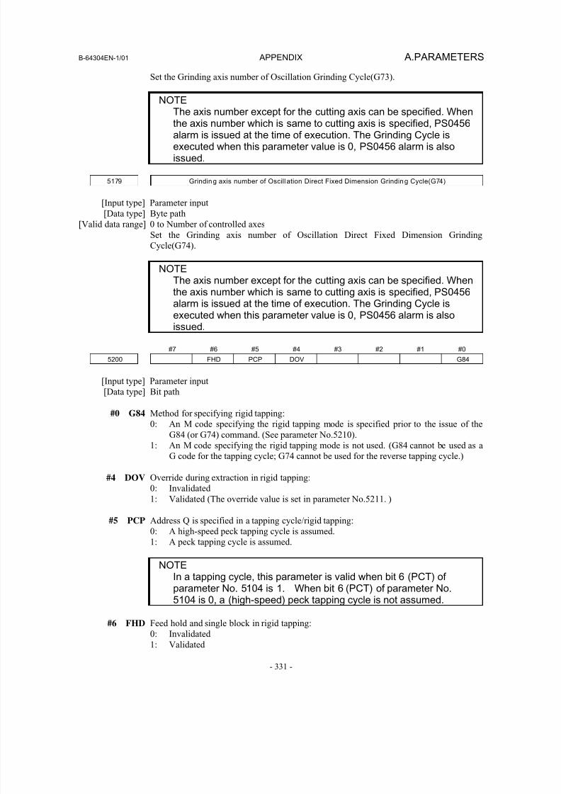
8/16/2019 Manual Operacion para FANUC
http://slidepdf.com/reader/full/manual-operacion-para-fanuc 349/435
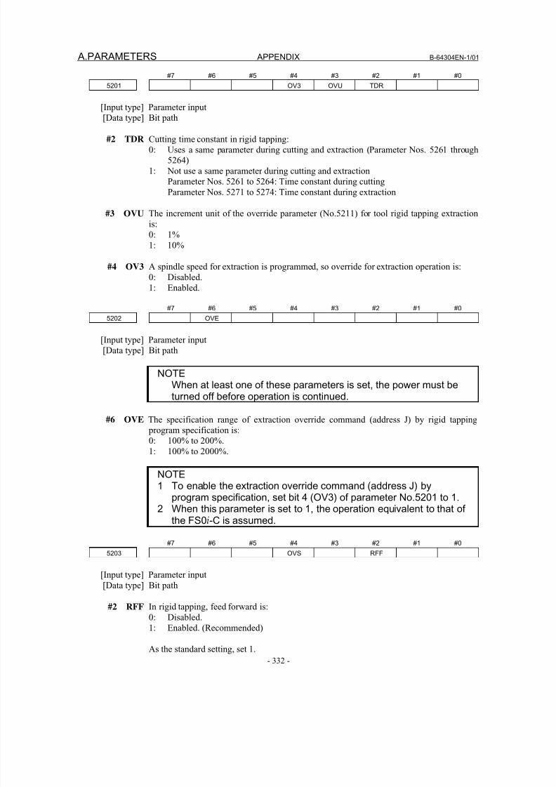
8/16/2019 Manual Operacion para FANUC
http://slidepdf.com/reader/full/manual-operacion-para-fanuc 350/435
A.PARAMETERS APPENDIX B-64304EN-1/01
- 332 -
#7 #6 #5 #4 #3 #2 #1 #0
5201 OV3 OVU TDR
[Input type] Parameter input
[Data type] Bit path
#2 TDR Cutting time constant in rigid tapping:
0: Uses a same parameter during cutting and extraction (Parameter Nos. 5261 through
5264)
1: Not use a same parameter during cutting and extraction
Parameter Nos. 5261 to 5264: Time constant during cutting
Parameter Nos. 5271 to 5274: Time constant during extraction
#3 OVU The increment unit of the override parameter (No.5211) for tool rigid tapping extraction
is:
0: 1%
1: 10%
#4 OV3 A spindle speed for extraction is programmed, so override for extraction operation is:
0: Disabled.
1: Enabled.
#7 #6 #5 #4 #3 #2 #1 #0
5202 OVE
[Input type] Parameter input
[Data type] Bit path
NOTEWhen at least one of these parameters is set, the power must beturned off before operation is continued.
#6 OVE The specification range of extraction override command (address J) by rigid tapping
program specification is:
0: 100% to 200%.
1: 100% to 2000%.
NOTE1 To enable the extraction override command (address J) by
program specification, set bit 4 (OV3) of parameter No.5201 to 1.2 When this parameter is set to 1, the operation equivalent to that of
the FS0i-C is assumed.
#7 #6 #5 #4 #3 #2 #1 #0
5203 OVS RFF
[Input type] Parameter input
[Data type] Bit path
#2 RFF In rigid tapping, feed forward is:
0: Disabled.1: Enabled. (Recommended)
As the standard setting, set 1.
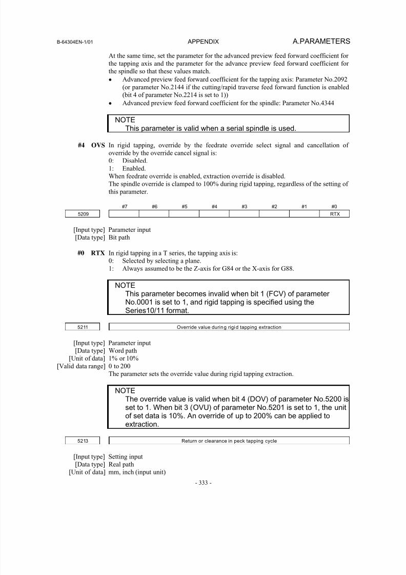
8/16/2019 Manual Operacion para FANUC
http://slidepdf.com/reader/full/manual-operacion-para-fanuc 351/435
B-64304EN-1/01 APPENDIX A.PARAMETERS
- 333 -
At the same time, set the parameter for the advanced preview feed forward coefficient for
the tapping axis and the parameter for the advance preview feed forward coefficient for
the spindle so that these values match.
• Advanced preview feed forward coefficient for the tapping axis: Parameter No.2092
(or parameter No.2144 if the cutting/rapid traverse feed forward function is enabled(bit 4 of parameter No.2214 is set to 1))
• Advanced preview feed forward coefficient for the spindle: Parameter No.4344
NOTEThis parameter is valid when a serial spindle is used.
#4 OVS In rigid tapping, override by the feedrate override select signal and cancellation of
override by the override cancel signal is:
0: Disabled.
1: Enabled.
When feedrate override is enabled, extraction override is disabled.
The spindle override is clamped to 100% during rigid tapping, regardless of the setting of
this parameter.
#7 #6 #5 #4 #3 #2 #1 #0
5209 RTX
[Input type] Parameter input
[Data type] Bit path
#0 RTX In rigid tapping in a T series, the tapping axis is:
0: Selected by selecting a plane.
1: Always assumed to be the Z-axis for G84 or the X-axis for G88.
NOTEThis parameter becomes invalid when bit 1 (FCV) of parameterNo.0001 is set to 1, and rigid tapping is specified using theSeries10/11 format.
5211 Override value during rigid tapping extraction
[Input type] Parameter input
[Data type] Word path
[Unit of data] 1% or 10%[Valid data range] 0 to 200
The parameter sets the override value during rigid tapping extraction.
NOTEThe override value is valid when bit 4 (DOV) of parameter No.5200 isset to 1. When bit 3 (OVU) of parameter No.5201 is set to 1, the unitof set data is 10%. An override of up to 200% can be applied toextraction.
5213 Return or clearance in peck tapping cycle
[Input type] Setting input
[Data type] Real path
[Unit of data] mm, inch (input unit)
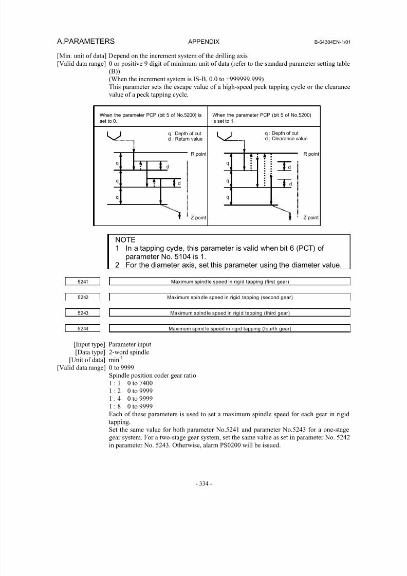
8/16/2019 Manual Operacion para FANUC
http://slidepdf.com/reader/full/manual-operacion-para-fanuc 352/435
A.PARAMETERS APPENDIX B-64304EN-1/01
- 334 -
[Min. unit of data] Depend on the increment system of the drilling axis
[Valid data range] 0 or positive 9 digit of minimum unit of data (refer to the standard parameter setting table
(B))
(When the increment system is IS-B, 0.0 to +999999.999)
This parameter sets the escape value of a high-speed peck tapping cycle or the clearance
value of a peck tapping cycle.
When the parameter PCP (bit 5 of No.5200) is
set to 0.
When the parameter PCP (bit 5 of No.5200)
is set to 1.
q : Depth of cutd : Return value
R point
Z point
q : Depth of cutd : Clearance value
R point
Z point
qd
dq
q
d
d
q
q
q
NOTE1 In a tapping cycle, this parameter is valid when bit 6 (PCT) of
parameter No. 5104 is 1.2 For the diameter axis, set this parameter using the diameter value.
5241 Maximum spind le speed in rigid tapping (first gear)
5242 Maximum spindle speed in rigid tapping (second gear)
5243 Maximum spind le speed in rigid tapping (third gear)
5244 Maximum spind le speed in rigid tapping (fourth gear)
[Input type] Parameter input
[Data type] 2-word spindle
[Unit of data] min
-1
[Valid data range] 0 to 9999
Spindle position coder gear ratio
1 : 1 0 to 7400
1 : 2 0 to 9999
1 : 4 0 to 9999
1 : 8 0 to 9999
Each of these parameters is used to set a maximum spindle speed for each gear in rigid
tapping.
Set the same value for both parameter No.5241 and parameter No.5243 for a one-stage
gear system. For a two-stage gear system, set the same value as set in parameter No. 5242
in parameter No. 5243. Otherwise, alarm PS0200 will be issued.
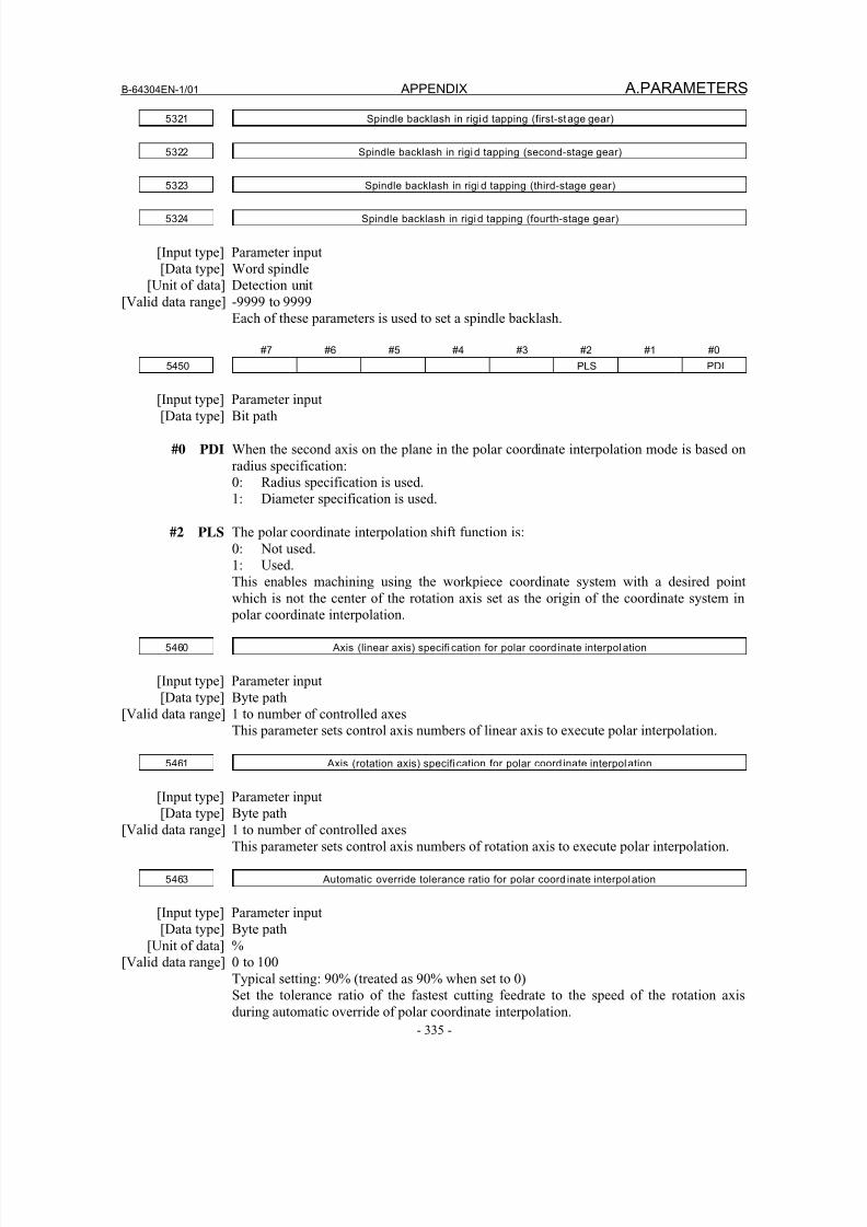
8/16/2019 Manual Operacion para FANUC
http://slidepdf.com/reader/full/manual-operacion-para-fanuc 353/435
B-64304EN-1/01 APPENDIX A.PARAMETERS
- 335 -
5321 Spindle backlash in rigid tapping (first-stage gear)
5322 Spindle backlash in rigid tapping (second-stage gear)
5323 Spindle backlash in rigid tapping (third-stage gear)
5324 Spindle backlash in rigid tapping (fourth-stage gear)
[Input type] Parameter input
[Data type] Word spindle
[Unit of data] Detection unit
[Valid data range] -9999 to 9999
Each of these parameters is used to set a spindle backlash.
#7 #6 #5 #4 #3 #2 #1 #0
5450 PLS PDI
[Input type] Parameter input
[Data type] Bit path
#0 PDI When the second axis on the plane in the polar coordinate interpolation mode is based on
radius specification:
0: Radius specification is used.
1: Diameter specification is used.
#2 PLS The polar coordinate interpolation shift function is:
0: Not used.
1: Used.
This enables machining using the workpiece coordinate system with a desired pointwhich is not the center of the rotation axis set as the origin of the coordinate system in
polar coordinate interpolation.
5460 Axis (linear axis) specifi cation for polar coord inate interpol ation
[Input type] Parameter input
[Data type] Byte path
[Valid data range] 1 to number of controlled axes
This parameter sets control axis numbers of linear axis to execute polar interpolation.
5461 Axis (rotation axis) specifi cation for polar coord inate interpolation
[Input type] Parameter input
[Data type] Byte path
[Valid data range] 1 to number of controlled axes
This parameter sets control axis numbers of rotation axis to execute polar interpolation.
5463 Automatic override tolerance ratio for polar coord inate interpolation
[Input type] Parameter input
[Data type] Byte path
[Unit of data] %
[Valid data range] 0 to 100Typical setting: 90% (treated as 90% when set to 0)
Set the tolerance ratio of the fastest cutting feedrate to the speed of the rotation axis
during automatic override of polar coordinate interpolation.
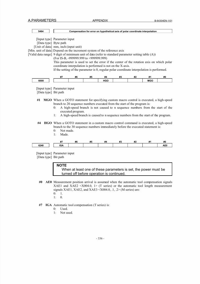
8/16/2019 Manual Operacion para FANUC
http://slidepdf.com/reader/full/manual-operacion-para-fanuc 354/435
A.PARAMETERS APPENDIX B-64304EN-1/01
- 336 -
5464 Compensation for error on hypothetical axis of polar coordinate interpolation
[Input type] Parameter input
[Data type] Byte path[Unit of data] mm, inch (input unit)
[Min. unit of data] Depend on the increment system of the reference axis
[Valid data range] 9 digit of minimum unit of data (refer to standard parameter setting table (A))
(For IS-B, -999999.999 to +999999.999)
This parameter is used to set the error if the center of the rotation axis on which polar
coordinate interpolation is performed is not on the X-axis.
If the setting of the parameter is 0, regular polar coordinate interpolation is performed.
#7 #6 #5 #4 #3 #2 #1 #0
6000 HGO MGO
[Input type] Parameter input[Data type] Bit path
#1 MGO When a GOTO statement for specifying custom macro control is executed, a high-speed
branch to 20 sequence numbers executed from the start of the program is:
0: A high-speed branch is not caused to n sequence numbers from the start of the
executed program.
1: A high-speed branch is caused to n sequence numbers from the start of the program.
#4 HGO When a GOTO statement in a custom macro control command is executed, a high-speed
branch to the 30 sequence numbers immediately before the executed statement is:
0: Not made.
1: Made.
#7 #6 #5 #4 #3 #2 #1 #0
6240 IGA AE0
[Input type] Parameter input
[Data type] Bit path
NOTEWhen at least one of these parameters is set, the power must beturned off before operation is continued.
#0 AE0 Measurement position arrival is assumed when the automatic tool compensation signals
XAE1 and XAE2 <X004.0, 1> (T series) or the automatic tool length measurement
signals XAE1, XAE2, and XAE3 <X004.0, .1, .2> (M series) are:
0: 1.
1: 0.
#7 IGA Automatic tool compensation (T series) is:
0: Used.
1: Not used.
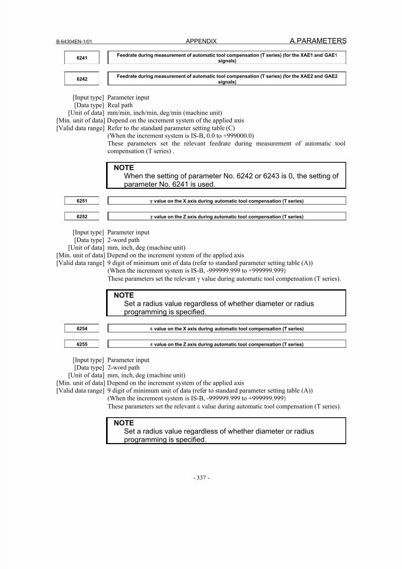
8/16/2019 Manual Operacion para FANUC
http://slidepdf.com/reader/full/manual-operacion-para-fanuc 355/435
B-64304EN-1/01 APPENDIX A.PARAMETERS
- 337 -
6241Feedrate during measurement of automatic tool compensation (T series) (for the XAE1 and GAE1
signals)
6242Feedrate during measurement of automatic tool compensation (T series) (for the XAE2 and GAE2
signals)
[Input type] Parameter input
[Data type] Real path
[Unit of data] mm/min, inch/min, deg/min (machine unit)
[Min. unit of data] Depend on the increment system of the applied axis
[Valid data range] Refer to the standard parameter setting table (C)
(When the increment system is IS-B, 0.0 to +999000.0)
These parameters set the relevant feedrate during measurement of automatic tool
compensation (T series) .
NOTE
When the setting of parameter No. 6242 or 6243 is 0, the setting ofparameter No. 6241 is used.
6251 value on the X axis during automatic tool compensation (T series)
6252 value on the Z axis during automatic tool compensation (T series)
[Input type] Parameter input
[Data type] 2-word path
[Unit of data] mm, inch, deg (machine unit)
[Min. unit of data] Depend on the increment system of the applied axis
[Valid data range] 9 digit of minimum unit of data (refer to standard parameter setting table (A))
(When the increment system is IS-B, -999999.999 to +999999.999)
These parameters set the relevant γ value during automatic tool compensation (T series).
NOTESet a radius value regardless of whether diameter or radiusprogramming is specified.
6254 value on the X axis during automatic tool compensation (T series)
6255 value on the Z axis during automatic tool compensation (T series)
[Input type] Parameter input[Data type] 2-word path
[Unit of data] mm, inch, deg (machine unit)
[Min. unit of data] Depend on the increment system of the applied axis
[Valid data range] 9 digit of minimum unit of data (refer to standard parameter setting table (A))
(When the increment system is IS-B, -999999.999 to +999999.999)
These parameters set the relevant ε value during automatic tool compensation (T series).
NOTESet a radius value regardless of whether diameter or radiusprogramming is specified.
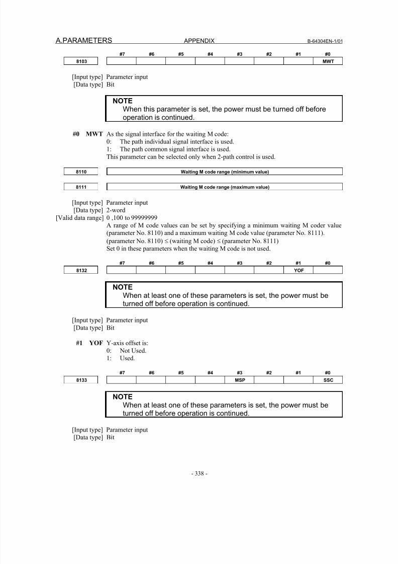
8/16/2019 Manual Operacion para FANUC
http://slidepdf.com/reader/full/manual-operacion-para-fanuc 356/435
A.PARAMETERS APPENDIX B-64304EN-1/01
- 338 -
#7 #6 #5 #4 #3 #2 #1 #0
8103 MWT
[Input type] Parameter input
[Data type] Bit
NOTEWhen this parameter is set, the power must be turned off beforeoperation is continued.
#0 MWT As the signal interface for the waiting M code:
0: The path individual signal interface is used.
1: The path common signal interface is used.
This parameter can be selected only when 2-path control is used.
8110 Waiting M code range (minimum value)
8111 Waiting M code range (maximum value)
[Input type] Parameter input
[Data type] 2-word
[Valid data range] 0 ,100 to 99999999
A range of M code values can be set by specifying a minimum waiting M coder value
(parameter No. 8110) and a maximum waiting M code value (parameter No. 8111).
(parameter No. 8110) ≤ (waiting M code) ≤ (parameter No. 8111)
Set 0 in these parameters when the waiting M code is not used.
#7 #6 #5 #4 #3 #2 #1 #0
8132 YOF
NOTEWhen at least one of these parameters is set, the power must beturned off before operation is continued.
[Input type] Parameter input
[Data type] Bit
#1 YOF Y-axis offset is:
0: Not Used.
1: Used.
#7 #6 #5 #4 #3 #2 #1 #0
8133 MSP SSC
NOTEWhen at least one of these parameters is set, the power must beturned off before operation is continued.
[Input type] Parameter input
[Data type] Bit
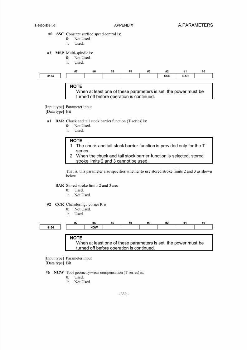
8/16/2019 Manual Operacion para FANUC
http://slidepdf.com/reader/full/manual-operacion-para-fanuc 357/435
B-64304EN-1/01 APPENDIX A.PARAMETERS
- 339 -
#0 SSC Constant surface speed control is:
0: Not Used.
1: Used.
#3 MSP Multi-spindle is:0: Not Used.
1: Used.
#7 #6 #5 #4 #3 #2 #1 #0
8134 CCR BAR
NOTEWhen at least one of these parameters is set, the power must beturned off before operation is continued.
[Input type] Parameter input
[Data type] Bit
#1 BAR Chuck and tail stock barrier function (T series) is:
0: Not Used.
1: Used.
NOTE1 The chuck and tail stock barrier function is provided only for the T
series.2 When the chuck and tail stock barrier function is selected, stored
stroke limits 2 and 3 cannot be used.
That is, this parameter also specifies whether to use stored stroke limits 2 and 3 as shown
below.
BAR Stored stroke limits 2 and 3 are:
0: Used.
1: Not Used.
#2 CCR Chamfering / corner R is:
0: Not Used.
1: Used.
#7 #6 #5 #4 #3 #2 #1 #0
8136 NGW
NOTEWhen at least one of these parameters is set, the power must beturned off before operation is continued.
[Input type] Parameter input
[Data type] Bit
#6 NGW Tool geometry/wear compensation (T series) is:
0: Used.
1: Not Used.
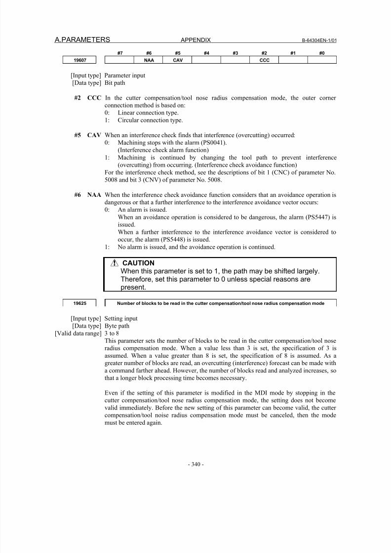
8/16/2019 Manual Operacion para FANUC
http://slidepdf.com/reader/full/manual-operacion-para-fanuc 358/435
A.PARAMETERS APPENDIX B-64304EN-1/01
- 340 -
#7 #6 #5 #4 #3 #2 #1 #0
19607 NAA CAV CCC
[Input type] Parameter input
[Data type] Bit path
#2 CCC In the cutter compensation/tool nose radius compensation mode, the outer corner
connection method is based on:
0: Linear connection type.
1: Circular connection type.
#5 CAV When an interference check finds that interference (overcutting) occurred:
0: Machining stops with the alarm (PS0041).
(Interference check alarm function)
1: Machining is continued by changing the tool path to prevent interference
(overcutting) from occurring. (Interference check avoidance function)
For the interference check method, see the descriptions of bit 1 (CNC) of parameter No.5008 and bit 3 (CNV) of parameter No. 5008.
#6 NAA When the interference check avoidance function considers that an avoidance operation is
dangerous or that a further interference to the interference avoidance vector occurs:
0: An alarm is issued.
When an avoidance operation is considered to be dangerous, the alarm (PS5447) is
issued.
When a further interference to the interference avoidance vector is considered to
occur, the alarm (PS5448) is issued.
1: No alarm is issued, and the avoidance operation is continued.
CAUTIONWhen this parameter is set to 1, the path may be shifted largely.Therefore, set this parameter to 0 unless special reasons arepresent.
19625 Number of blocks to be read in the cutter compensation/tool nose radius compensation mode
[Input type] Setting input
[Data type] Byte path
[Valid data range] 3 to 8
This parameter sets the number of blocks to be read in the cutter compensation/tool nose
radius compensation mode. When a value less than 3 is set, the specification of 3 isassumed. When a value greater than 8 is set, the specification of 8 is assumed. As a
greater number of blocks are read, an overcutting (interference) forecast can be made with
a command farther ahead. However, the number of blocks read and analyzed increases, so
that a longer block processing time becomes necessary.
Even if the setting of this parameter is modified in the MDI mode by stopping in the
cutter compensation/tool nose radius compensation mode, the setting does not become
valid immediately. Before the new setting of this parameter can become valid, the cutter
compensation/tool noise radius compensation mode must be canceled, then the mode
must be entered again.
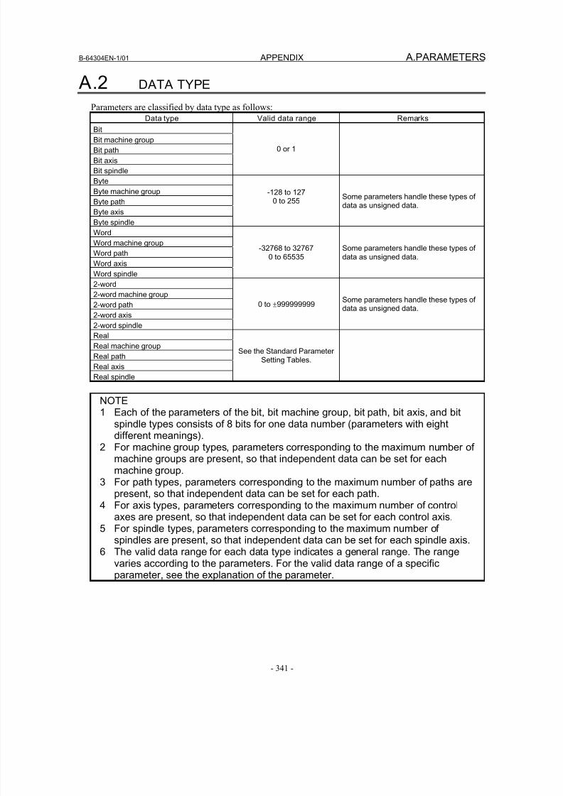
8/16/2019 Manual Operacion para FANUC
http://slidepdf.com/reader/full/manual-operacion-para-fanuc 359/435
B-64304EN-1/01 APPENDIX A.PARAMETERS
- 341 -
A.2 DATA TYPE
Parameters are classified by data type as follows:
Data type Valid data range Remarks
Bit
Bit machine group
Bit path
Bit axis
Bit spindle
0 or 1
Byte
Byte machine group
Byte path
Byte axis
Byte spindle
-128 to 1270 to 255
Some parameters handle these types ofdata as unsigned data.
Word
Word machine group
Word path
Word axis
Word spindle
-32768 to 327670 to 65535
Some parameters handle these types ofdata as unsigned data.
2-word
2-word machine group
2-word path
2-word axis
2-word spindle
0 to ±999999999Some parameters handle these types ofdata as unsigned data.
Real
Real machine group
Real path
Real axis
Real spindle
See the Standard ParameterSetting Tables.
NOTE1 Each of the parameters of the bit, bit machine group, bit path, bit axis, and bit
spindle types consists of 8 bits for one data number (parameters with eightdifferent meanings).
2 For machine group types, parameters corresponding to the maximum number ofmachine groups are present, so that independent data can be set for eachmachine group.
3 For path types, parameters corresponding to the maximum number of paths arepresent, so that independent data can be set for each path.
4 For axis types, parameters corresponding to the maximum number of controlaxes are present, so that independent data can be set for each control axis.
5 For spindle types, parameters corresponding to the maximum number ofspindles are present, so that independent data can be set for each spindle axis.
6 The valid data range for each data type indicates a general range. The rangevaries according to the parameters. For the valid data range of a specificparameter, see the explanation of the parameter.
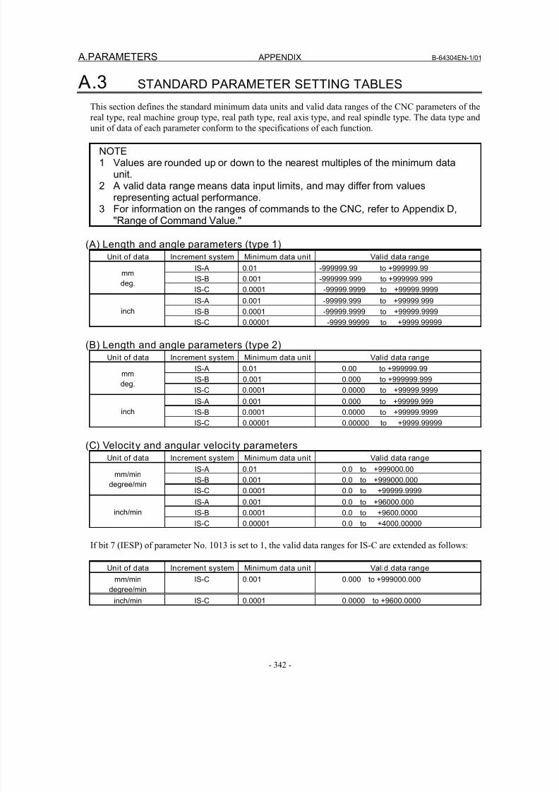
8/16/2019 Manual Operacion para FANUC
http://slidepdf.com/reader/full/manual-operacion-para-fanuc 360/435
A.PARAMETERS APPENDIX B-64304EN-1/01
- 342 -
A.3 STANDARD PARAMETER SETTING TABLES
This section defines the standard minimum data units and valid data ranges of the CNC parameters of the
real type, real machine group type, real path type, real axis type, and real spindle type. The data type and
unit of data of each parameter conform to the specifications of each function.
NOTE1 Values are rounded up or down to the nearest multiples of the minimum data
unit.2 A valid data range means data input limits, and may differ from values
representing actual performance.3 For information on the ranges of commands to the CNC, refer to Appendix D,
"Range of Command Value."
(A) Length and angle parameters (type 1)Unit of data Increment system Minimum data unit Valid data range
IS-A 0.01 -999999.99 to +999999.99
IS-B 0.001 -999999.999 to +999999.999mm
deg. IS-C 0.0001 -99999.9999 to +99999.9999
IS-A 0.001 -99999.999 to +99999.999
IS-B 0.0001 -99999.9999 to +99999.9999inch
IS-C 0.00001 -9999.99999 to +9999.99999
(B) Length and angle parameters (type 2)Unit of data Increment system Minimum data unit Valid data range
IS-A 0.01 0.00 to +999999.99
IS-B 0.001 0.000 to +999999.999mmdeg.
IS-C 0.0001 0.0000 to +99999.9999
IS-A 0.001 0.000 to +99999.999
IS-B 0.0001 0.0000 to +99999.9999inch
IS-C 0.00001 0.00000 to +9999.99999
(C) Velocity and angular veloci ty parametersUnit of data Increment system Minimum data unit Valid data range
IS-A 0.01 0.0 to +999000.00
IS-B 0.001 0.0 to +999000.000mm/min
degree/minIS-C 0.0001 0.0 to +99999.9999
IS-A 0.001 0.0 to +96000.000
IS-B 0.0001 0.0 to +9600.0000inch/min
IS-C 0.00001 0.0 to +4000.00000
If bit 7 (IESP) of parameter No. 1013 is set to 1, the valid data ranges for IS-C are extended as follows:
Unit of data Increment system Minimum data unit Valid data range
mm/min
degree/min
IS-C 0.001 0.000 to +999000.000
inch/min IS-C 0.0001 0.0000 to +9600.0000
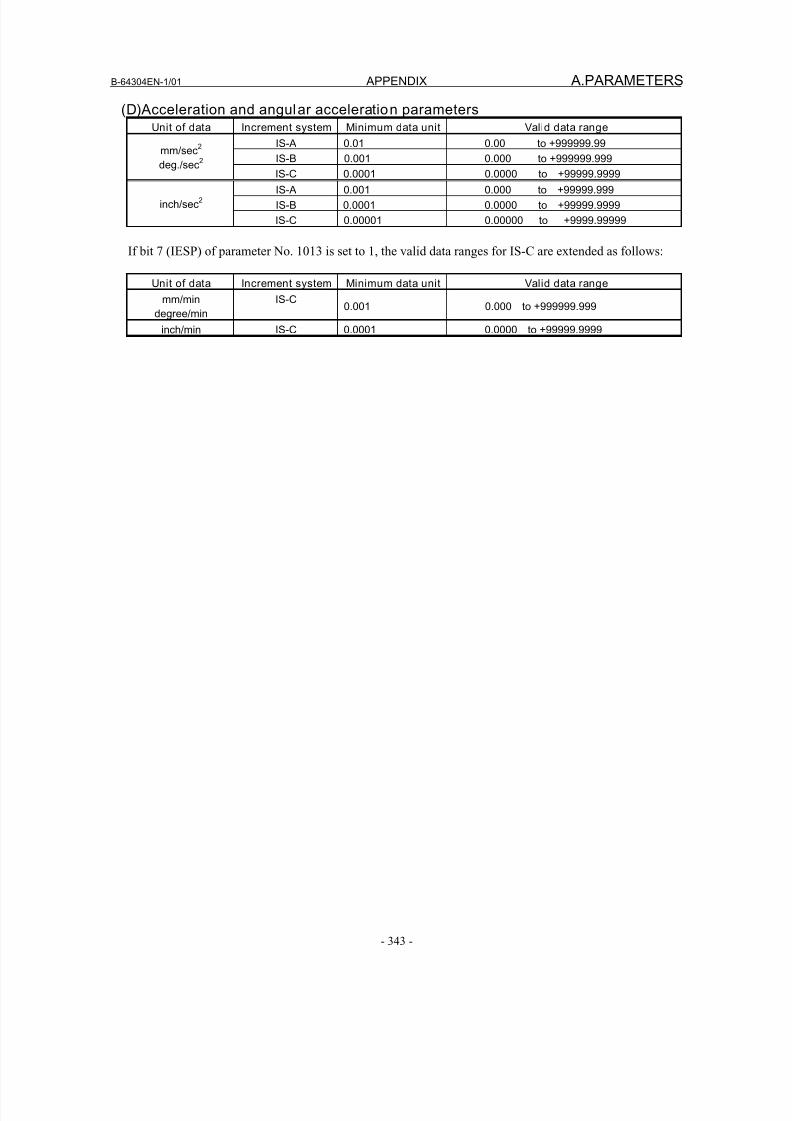
8/16/2019 Manual Operacion para FANUC
http://slidepdf.com/reader/full/manual-operacion-para-fanuc 361/435
B-64304EN-1/01 APPENDIX A.PARAMETERS
- 343 -
(D)Acceleration and angular acceleration parametersUnit of data Increment system Minimum data unit Valid data range
IS-A 0.01 0.00 to +999999.99
IS-B 0.001 0.000 to +999999.999mm/sec
2
deg./sec2
IS-C 0.0001 0.0000 to +99999.9999IS-A 0.001 0.000 to +99999.999
IS-B 0.0001 0.0000 to +99999.9999inch/sec2
IS-C 0.00001 0.00000 to +9999.99999
If bit 7 (IESP) of parameter No. 1013 is set to 1, the valid data ranges for IS-C are extended as follows:
Unit of data Increment system Minimum data unit Valid data range
mm/min
degree/min
IS-C0.001 0.000 to +999999.999
inch/min IS-C 0.0001 0.0000 to +99999.9999
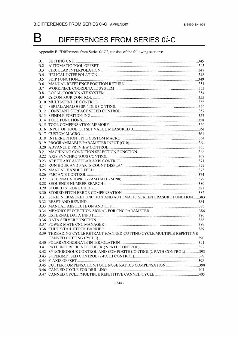
8/16/2019 Manual Operacion para FANUC
http://slidepdf.com/reader/full/manual-operacion-para-fanuc 362/435
B.DIFFERENCES FROM SERIES 0i-C APPENDIX B-64304EN-1/01
- 344 -
B DIFFERENCES FROM SERIES 0i-C
Appendix B, "Differences from Series 0i-C", consists of the following sections:
B.1 SETTING UNIT .............................................................................................................................345
B.2 AUTOMATIC TOOL OFFSET......................................................................................................345
B.3 CIRCULAR INTERPOLATION....................................................................................................347
B.4 HELICAL INTERPOLATION.......................................................................................................348
B.5 SKIP FUNCTION...........................................................................................................................349
B.6 MANUAL REFERENCE POSITION RETURN ...........................................................................351
B.7 WORKPIECE COORDINATE SYSTEM......................................................................................353
B.8 LOCAL COORDINATE SYSTEM................................................................................................354
B.9 Cs CONTOUR CONTROL ............................................................................................................355
B.10 MULTI-SPINDLE CONTROL ......................................................................................................355
B.11 SERIAL/ANALOG SPINDLE CONTROL....................................................................................356B.12 CONSTANT SURFACE SPEED CONTROL ...............................................................................357
B.13 SPINDLE POSITIONING..............................................................................................................357
B.14 TOOL FUNCTIONS.......................................................................................................................358
B.15 TOOL COMPENSATION MEMORY...........................................................................................360
B.16 INPUT OF TOOL OFFSET VALUE MEASURED B...................................................................361
B.17 CUSTOM MACRO ........................................................................................................................361
B.18 INTERRUPTION TYPE CUSTOM MACRO ...............................................................................364
B.19 PROGRAMMABLE PARAMETER INPUT (G10).......................................................................364
B.20 ADVANCED PREVIEW CONTROL............................................................................................365
B.21 MACHINING CONDITION SELECTION FUNCTION ..............................................................366
B.22 AXIS SYNCHRONOUS CONTROL.............................................................................................367
B.23 ARBITRARY ANGULAR AXIS CONTROL ...............................................................................371
B.24 RUN HOUR AND PARTS COUNT DISPLAY ............................................................................372
B.25 MANUAL HANDLE FEED...........................................................................................................373
B.26 PMC AXIS CONTROL ..................................................................................................................374
B.27 EXTERNAL SUBPROGRAM CALL (M198)...............................................................................379
B.28 SEQUENCE NUMBER SEARCH .................................................................................................380
B.29 STORED STROKE CHECK ..........................................................................................................381
B.30 STORED PITCH ERROR COMPENSATION ..............................................................................382
B.31 SCREEN ERASURE FUNCTION AND AUTOMATIC SCREEN ERASURE FUNCTION......383
B.32 RESET AND REWIND..................................................................................................................384
B.33 MANUAL ABSOLUTE ON AND OFF.........................................................................................385
B.34 MEMORY PROTECTION SIGNAL FOR CNC PARAMETER ..................................................386B.35 EXTERNAL DATA INPUT...........................................................................................................386
B.36 DATA SERVER FUNCTION ........................................................................................................388
B.37 POWER MATE CNC MANAGER ................................................................................................389
B.38 CHUCK/TAIL STOCK BARRIER ................................................................................................389
B.39 THREADING CYCLE RETRACT (CANNED CUTTING CYCLE/MULTIPLE REPETITIVE
CANNED CUTTING CYCLE) ......................................................................................................390
B.40 POLAR COORDINATE INTERPOLATION ................................................................................391
B.41 PATH INTERFERENCE CHECK (2-PATH CONTROL) ............................................................392
B.42 SYNCHRONOUS CONTROL AND COMPOSITE CONTROL(2-PATH CONTROL)..............393
B.43 SUPERIMPOSED CONTROL (2-PATH CONTROL)..................................................................397
B.44 Y AXIS OFFSET ............................................................................................................................398
B.45 CUTTER COMPENSATION/TOOL NOSE RADIUS COMPENSATION..................................398B.46 CANNED CYCLE FOR DRILLING .............................................................................................404
B.47 CANNED CYCLE /MULTIPLE REPETITIVE CANNED CYCLE.............................................405
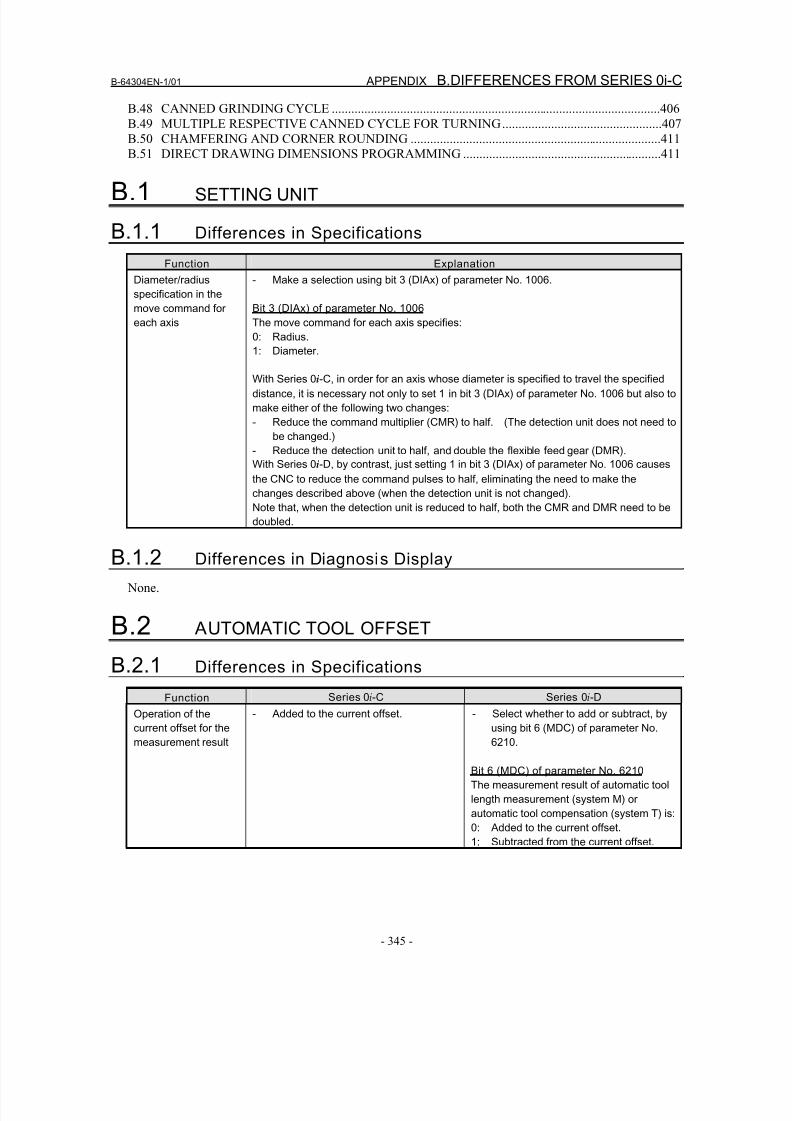
8/16/2019 Manual Operacion para FANUC
http://slidepdf.com/reader/full/manual-operacion-para-fanuc 363/435
B-64304EN-1/01 APPENDIX B.DIFFERENCES FROM SERIES 0i-C
- 345 -
B.48 CANNED GRINDING CYCLE .....................................................................................................406
B.49 MULTIPLE RESPECTIVE CANNED CYCLE FOR TURNING.................................................407
B.50 CHAMFERING AND CORNER ROUNDING .............................................................................411
B.51 DIRECT DRAWING DIMENSIONS PROGRAMMING .............................................................411
B.1 SETTING UNIT
B.1.1 Differences in Specifications
Function Explanation
Diameter/radius
specification in the
move command for
each axis
- Make a selection using bit 3 (DIAx) of parameter No. 1006.
Bit 3 (DIAx) of parameter No. 1006
The move command for each axis specifies:
0: Radius.
1: Diameter.
With Series 0i-C, in order for an axis whose diameter is specified to travel the specified
distance, it is necessary not only to set 1 in bit 3 (DIAx) of parameter No. 1006 but also to
make either of the following two changes:
- Reduce the command multiplier (CMR) to half. (The detection unit does not need to
be changed.)
- Reduce the detection unit to half, and double the flexible feed gear (DMR).
With Series 0i-D, by contrast, just setting 1 in bit 3 (DIAx) of parameter No. 1006 causes
the CNC to reduce the command pulses to half, eliminating the need to make the
changes described above (when the detection unit is not changed).
Note that, when the detection unit is reduced to half, both the CMR and DMR need to be
doubled.
B.1.2 Differences in Diagnosis Display
None.
B.2 AUTOMATIC TOOL OFFSET
B.2.1 Differences in Specifications
Function Series 0i-C Series 0i-D
Operation of the
current offset for the
measurement result
- Added to the current offset. - Select whether to add or subtract, by
using bit 6 (MDC) of parameter No.
6210.
Bit 6 (MDC) of parameter No. 6210
The measurement result of automatic tool
length measurement (system M) or
automatic tool compensation (system T) is:
0: Added to the current offset.
1: Subtracted from the current offset.
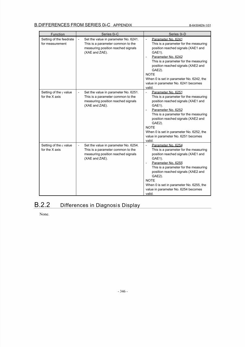
8/16/2019 Manual Operacion para FANUC
http://slidepdf.com/reader/full/manual-operacion-para-fanuc 364/435
B.DIFFERENCES FROM SERIES 0i-C APPENDIX B-64304EN-1/01
- 346 -
Function Series 0i-C Series 0i-D
Setting of the feedrate
for measurement
- Set the value in parameter No. 6241.
This is a parameter common to the
measuring position reached signals
(XAE and ZAE).
- Parameter No. 6241
This is a parameter for the measuring
position reached signals (XAE1 and
GAE1).
- Parameter No. 6242
This is a parameter for the measuring
position reached signals (XAE2 and
GAE2).
NOTE
When 0 is set in parameter No. 6242, the
value in parameter No. 6241 becomes
valid.
Setting of the γ value
for the X axis
- Set the value in parameter No. 6251.
This is a parameter common to the
measuring position reached signals
(XAE and ZAE).
- Parameter No. 6251
This is a parameter for the measuring
position reached signals (XAE1 and
GAE1).
- Parameter No. 6252 This is a parameter for the measuring
position reached signals (XAE2 and
GAE2).
NOTE
When 0 is set in parameter No. 6252, the
value in parameter No. 6251 becomes
valid.
Setting of the ε value
for the X axis
- Set the value in parameter No. 6254.
This is a parameter common to the
measuring position reached signals
(XAE and ZAE).
- Parameter No. 6254
This is a parameter for the measuring
position reached signals (XAE1 and
GAE1).
- Parameter No. 6255 This is a parameter for the measuring
position reached signals (XAE2 and
GAE2).
NOTE
When 0 is set in parameter No. 6255, the
value in parameter No. 6254 becomes
valid.
B.2.2 Differences in Diagnosis Display
None.
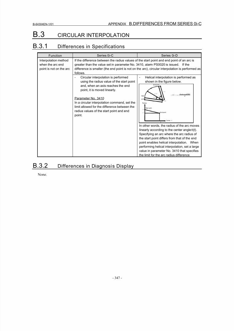
8/16/2019 Manual Operacion para FANUC
http://slidepdf.com/reader/full/manual-operacion-para-fanuc 365/435
B-64304EN-1/01 APPENDIX B.DIFFERENCES FROM SERIES 0i-C
- 347 -
B.3 CIRCULAR INTERPOLATION
B.3.1 Differences in Specifications
Function Series 0i-C Series 0i-D
If the difference between the radius values of the start point and end point of an arc is
greater than the value set in parameter No. 3410, alarm PS0020 is issued. If the
difference is smaller (the end point is not on the arc), circular interpolation is performed as
follows.
Interpolation method
when the arc end
point is not on the arc
- Circular interpolation is performed
using the radius value of the start point
and, when an axis reaches the end
point, it is moved linearly.
Parameter No. 3410
In a circular interpolation command, set thelimit allowed for the difference between the
radius values of the start point and end
point.
- Helical interpolation is performed as
shown in the figure below.
γe γ(t)
γs
Start
point
中心
End point
θ(t)θ
Start point
End point
Center θ θ
γs
γe
Radius
θ
t s) e ( s (t)
)(θγγγγ
−+=
In other words, the radius of the arc moves
linearly according to the center angle θ(t).
Specifying an arc where the arc radius of
the start point differs from that of the end
point enables helical interpolation. When
performing helical interpolation, set a large
value in parameter No. 3410 that specifies
the limit for the arc radius difference.
B.3.2 Differences in Diagnosis Display
None.
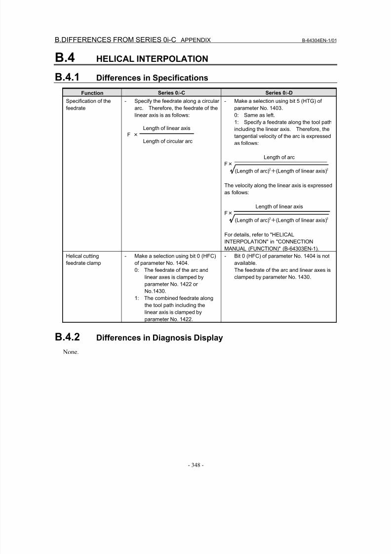
8/16/2019 Manual Operacion para FANUC
http://slidepdf.com/reader/full/manual-operacion-para-fanuc 366/435
B.DIFFERENCES FROM SERIES 0i-C APPENDIX B-64304EN-1/01
- 348 -
B.4 HELICAL INTERPOLATION
B.4.1 Differences in Specifications
Function Series 0i-C Series 0i-D
Specification of the
feedrate
- Specify the feedrate along a circular
arc. Therefore, the feedrate of the
linear axis is as follows:
Length of linear axis
F ×
Length of circular arc
- Make a selection using bit 5 (HTG) of
parameter No. 1403.
0: Same as left.
1: Specify a feedrate along the tool path
including the linear axis. Therefore, the
tangential velocity of the arc is expressed
as follows:
Length of arc
F×
(Length of arc)2+(Length of linear axis)2
The velocity along the linear axis is expressed
as follows:
Length of linear axis
F×
(Length of arc)2+(Length of linear axis)2
For details, refer to "HELICAL
INTERPOLATION" in "CONNECTION
MANUAL (FUNCTION)" (B-64303EN-1).
Helical cutting
feedrate clamp
- Make a selection using bit 0 (HFC)
of parameter No. 1404.
0: The feedrate of the arc and
linear axes is clamped by
parameter No. 1422 or
No.1430.
1: The combined feedrate along
the tool path including the
linear axis is clamped by
parameter No. 1422.
- Bit 0 (HFC) of parameter No. 1404 is not
available.
The feedrate of the arc and linear axes is
clamped by parameter No. 1430.
B.4.2 Differences in Diagnosis Display
None.
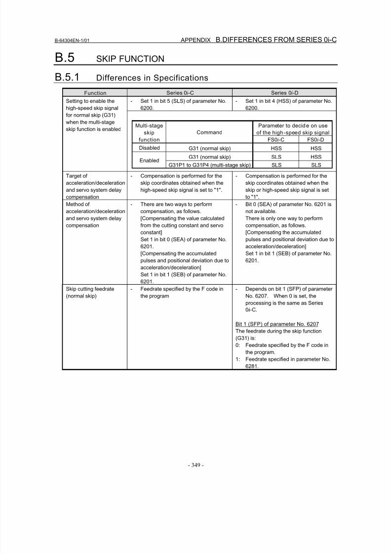
8/16/2019 Manual Operacion para FANUC
http://slidepdf.com/reader/full/manual-operacion-para-fanuc 367/435
B-64304EN-1/01 APPENDIX B.DIFFERENCES FROM SERIES 0i-C
- 349 -
B.5 SKIP FUNCTION
B.5.1 Differences in Specifications
Function Series 0i-C Series 0i-D
- Set 1 in bit 5 (SLS) of parameter No.
6200.
- Set 1 in bit 4 (HSS) of parameter No.
6200.
Setting to enable the
high-speed skip signal
for normal skip (G31)
when the multi-stage
skip function is enabledParameter to decide on use
of the high-speed skip signal
Multi-stage
skip
function
Command
FS0i-C FS0i-D
Disabled G31 (normal skip) HSS HSS
G31 (normal skip) SLS HSSEnabled
G31P1 to G31P4 (multi-stage skip) SLS SLS
Target of
acceleration/deceleration
and servo system delay
compensation
- Compensation is performed for the
skip coordinates obtained when the
high-speed skip signal is set to "1".
- Compensation is performed for the
skip coordinates obtained when the
skip or high-speed skip signal is set
to "1".
Method of
acceleration/deceleration
and servo system delay
compensation
- There are two ways to perform
compensation, as follows.
[Compensating the value calculated
from the cutting constant and servo
constant]
Set 1 in bit 0 (SEA) of parameter No.
6201.
[Compensating the accumulated
pulses and positional deviation due toacceleration/deceleration]
Set 1 in bit 1 (SEB) of parameter No.
6201.
- Bit 0 (SEA) of parameter No. 6201 is
not available.
There is only one way to perform
compensation, as follows.
[Compensating the accumulated
pulses and positional deviation due to
acceleration/deceleration]
Set 1 in bit 1 (SEB) of parameter No.
6201.
Skip cutting feedrate
(normal skip)
- Feedrate specified by the F code in
the program
- Depends on bit 1 (SFP) of parameter
No. 6207. When 0 is set, the
processing is the same as Series
0i-C.
Bit 1 (SFP) of parameter No. 6207
The feedrate during the skip function
(G31) is:
0: Feedrate specified by the F code in
the program.
1: Feedrate specified in parameter No.
6281.
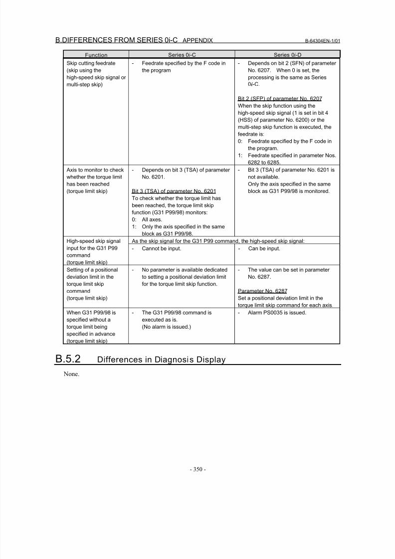
8/16/2019 Manual Operacion para FANUC
http://slidepdf.com/reader/full/manual-operacion-para-fanuc 368/435
B.DIFFERENCES FROM SERIES 0i-C APPENDIX B-64304EN-1/01
- 350 -
Function Series 0i-C Series 0i-D
Skip cutting feedrate
(skip using the
high-speed skip signal or
multi-step skip)
- Feedrate specified by the F code in
the program
- Depends on bit 2 (SFN) of parameter
No. 6207. When 0 is set, the
processing is the same as Series
0i-C.
Bit 2 (SFP) of parameter No. 6207
When the skip function using the
high-speed skip signal (1 is set in bit 4
(HSS) of parameter No. 6200) or the
multi-step skip function is executed, the
feedrate is:
0: Feedrate specified by the F code in
the program.
1: Feedrate specified in parameter Nos.
6282 to 6285.
Axis to monitor to check
whether the torque limithas been reached
(torque limit skip)
- Depends on bit 3 (TSA) of parameter
No. 6201.
Bit 3 (TSA) of parameter No. 6201
To check whether the torque limit has
been reached, the torque limit skip
function (G31 P99/98) monitors:
0: All axes.
1: Only the axis specified in the same
block as G31 P99/98.
- Bit 3 (TSA) of parameter No. 6201 is
not available.Only the axis specified in the same
block as G31 P99/98 is monitored.
As the skip signal for the G31 P99 command, the high-speed skip signal:High-speed skip signal
input for the G31 P99
command
(torque limit skip)
- Cannot be input. - Can be input.
Setting of a positional
deviation limit in the
torque limit skip
command
(torque limit skip)
- No parameter is available dedicated
to setting a positional deviation limit
for the torque limit skip function.
- The value can be set in parameter
No. 6287.
Parameter No. 6287
Set a positional deviation limit in the
torque limit skip command for each axis.
When G31 P99/98 is
specified without a
torque limit being
specified in advance
(torque limit skip)
- The G31 P99/98 command is
executed as is.
(No alarm is issued.)
- Alarm PS0035 is issued.
B.5.2 Differences in Diagnosis Display
None.
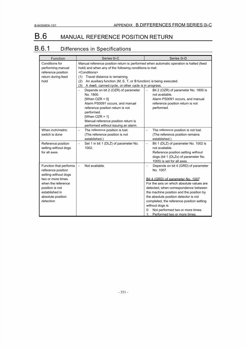
8/16/2019 Manual Operacion para FANUC
http://slidepdf.com/reader/full/manual-operacion-para-fanuc 369/435
B-64304EN-1/01 APPENDIX B.DIFFERENCES FROM SERIES 0i-C
- 351 -
B.6 MANUAL REFERENCE POSITION RETURN
B.6.1 Differences in Specifications
Function Series 0i-C Series 0i-D
Manual reference position return is performed when automatic operation is halted (feed
hold) and when any of the following conditions is met:
<Conditions>
(1) Travel distance is remaining.
(2) An auxiliary function (M, S, T, or B function) is being executed.
(3) A dwell, canned cycle, or other cycle is in progress.
Conditions for
performing manual
reference position
return during feed
hold
- Depends on bit 2 (OZR) of parameter
No. 1800.
[When OZR = 0]
Alarm PS0091 occurs, and manual
reference position return is notperformed.
[When OZR = 1]
Manual reference position return is
performed without issuing an alarm.
- Bit 2 (OZR) of parameter No. 1800 is
not available.
Alarm PS0091 occurs, and manual
reference position return is not
performed.
When inch/metric
switch is done
- The reference position is lost.
(The reference position is not
established.)
- The reference position is not lost.
(The reference position remains
established.)
Reference position
setting without dogs
for all axes
- Set 1 in bit 1 (DLZ) of parameter No.
1002.
- Bit 1 (DLZ) of parameter No. 1002 is
not available.
Reference position setting without
dogs (bit 1 (DLZx) of parameter No.
1005) is set for all axes.
Function that performs
reference position
setting without dogs
two or more times
when the reference
position is not
established in
absolute position
detection
- Not available. - Depends on bit 4 (GRD) of parameter
No. 1007.
Bit 4 (GRD) of parameter No. 1007
For the axis on which absolute values are
detected, when correspondence between
the machine position and the position by
the absolute position detector is not
completed, the reference position setting
without dogs is:
0: Not performed two or more times.
1: Performed two or more times.
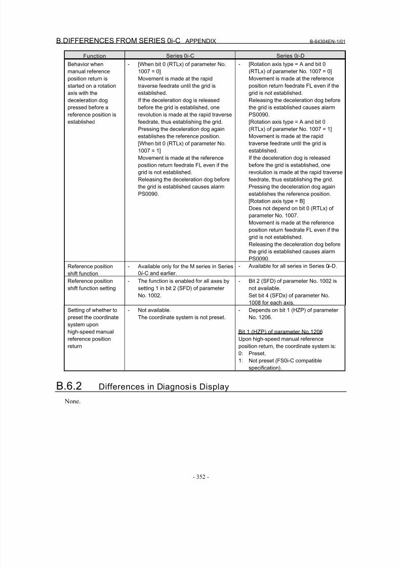
8/16/2019 Manual Operacion para FANUC
http://slidepdf.com/reader/full/manual-operacion-para-fanuc 370/435
B.DIFFERENCES FROM SERIES 0i-C APPENDIX B-64304EN-1/01
- 352 -
Function Series 0i-C Series 0i-D
Behavior when
manual reference
position return is
started on a rotation
axis with the
deceleration dog
pressed before a
reference position is
established
- [When bit 0 (RTLx) of parameter No.
1007 = 0]
Movement is made at the rapid
traverse feedrate until the grid is
established.
If the deceleration dog is released
before the grid is established, one
revolution is made at the rapid traverse
feedrate, thus establishing the grid.
Pressing the deceleration dog again
establishes the reference position.
[When bit 0 (RTLx) of parameter No.
1007 = 1]
Movement is made at the reference
position return feedrate FL even if the
grid is not established.
Releasing the deceleration dog beforethe grid is established causes alarm
PS0090.
- [Rotation axis type = A and bit 0
(RTLx) of parameter No. 1007 = 0]
Movement is made at the reference
position return feedrate FL even if the
grid is not established.
Releasing the deceleration dog before
the grid is established causes alarm
PS0090.
[Rotation axis type = A and bit 0
(RTLx) of parameter No. 1007 = 1]
Movement is made at the rapid
traverse feedrate until the grid is
established.
If the deceleration dog is released
before the grid is established, one
revolution is made at the rapid traverse
feedrate, thus establishing the grid.Pressing the deceleration dog again
establishes the reference position.
[Rotation axis type = B]
Does not depend on bit 0 (RTLx) of
parameter No. 1007.
Movement is made at the reference
position return feedrate FL even if the
grid is not established.
Releasing the deceleration dog before
the grid is established causes alarm
PS0090.
Reference positionshift function
- Available only for the M series in Series0i-C and earlier.
- Available for all series in Series 0i-D.
Reference position
shift function setting
- The function is enabled for all axes by
setting 1 in bit 2 (SFD) of parameter
No. 1002.
- Bit 2 (SFD) of parameter No. 1002 is
not available.
Set bit 4 (SFDx) of parameter No.
1008 for each axis.
Setting of whether to
preset the coordinate
system upon
high-speed manual
reference position
return
- Not available.
The coordinate system is not preset.
- Depends on bit 1 (HZP) of parameter
No. 1206.
Bit 1 (HZP) of parameter No.1206
Upon high-speed manual reference
position return, the coordinate system is:
0: Preset.
1: Not preset (FS0i-C compatible
specification).
B.6.2 Differences in Diagnosis Display
None.
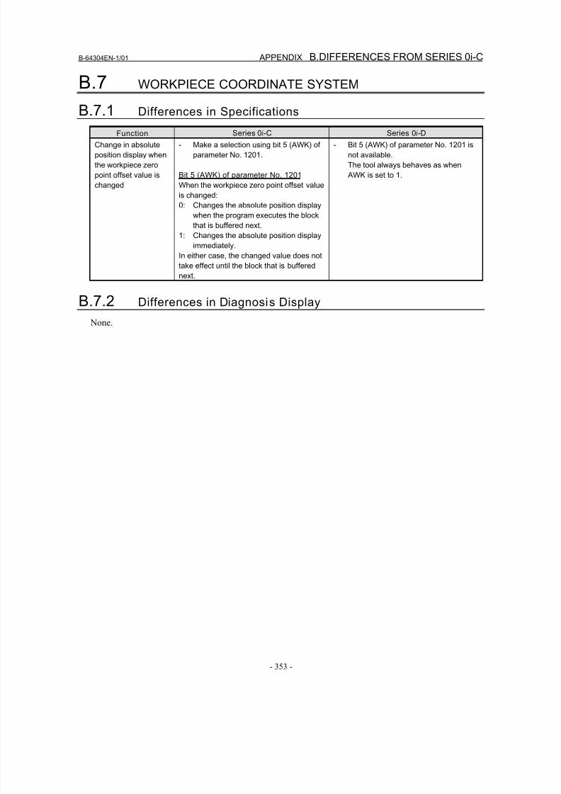
8/16/2019 Manual Operacion para FANUC
http://slidepdf.com/reader/full/manual-operacion-para-fanuc 371/435
B-64304EN-1/01 APPENDIX B.DIFFERENCES FROM SERIES 0i-C
- 353 -
B.7 WORKPIECE COORDINATE SYSTEM
B.7.1 Differences in Specifications
Function Series 0i-C Series 0i-D
Change in absolute
position display when
the workpiece zero
point offset value is
changed
- Make a selection using bit 5 (AWK) of
parameter No. 1201.
Bit 5 (AWK) of parameter No. 1201
When the workpiece zero point offset value
is changed:
0: Changes the absolute position display
when the program executes the block
that is buffered next.
1: Changes the absolute position display
immediately.In either case, the changed value does not
take effect until the block that is buffered
next.
- Bit 5 (AWK) of parameter No. 1201 is
not available.
The tool always behaves as when
AWK is set to 1.
B.7.2 Differences in Diagnosis Display
None.
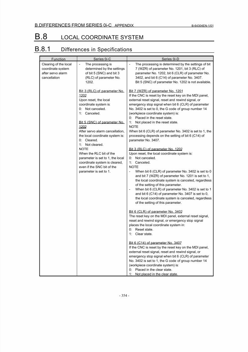
8/16/2019 Manual Operacion para FANUC
http://slidepdf.com/reader/full/manual-operacion-para-fanuc 372/435
B.DIFFERENCES FROM SERIES 0i-C APPENDIX B-64304EN-1/01
- 354 -
B.8 LOCAL COORDINATE SYSTEM
B.8.1 Differences in Specifications
Function Series 0i-C Series 0i-D
Clearing of the local
coordinate system
after servo alarm
cancellation
- The processing is
determined by the settings
of bit 5 (SNC) and bit 3
(RLC) of parameter No.
1202.
Bit 3 (RLC) of parameter No.
1202
Upon reset, the local
coordinate system is:
0: Not canceled.1: Canceled.
Bit 5 (SNC) of parameter No.
1202
After servo alarm cancellation,
the local coordinate system is:
0: Cleared.
1: Not cleared.
NOTE
When the RLC bit of the
parameter is set to 1, the local
coordinate system is cleared,
even if the SNC bit of the
parameter is set to 1.
- The processing is determined by the settings of bit
7 (WZR) of parameter No. 1201, bit 3 (RLC) of
parameter No. 1202, bit 6 (CLR) of parameter No.
3402, and bit 6 (C14) of parameter No. 3407.
Bit 5 (SNC) of parameter No. 1202 is not available.
Bit 7 (WZR) of parameter No. 1201
If the CNC is reset by the reset key on the MDI panel,
external reset signal, reset and rewind signal, or
emergency stop signal when bit 6 (CLR) of parameter
No. 3402 is set to 0, the G code of group number 14(workpiece coordinate system) is:
0: Placed in the reset state.
1: Not placed in the reset state.
NOTE
When bit 6 (CLR) of parameter No. 3402 is set to 1, the
processing depends on the setting of bit 6 (C14) of
parameter No. 3407.
Bit 3 (RLC) of parameter No. 1202
Upon reset, the local coordinate system is:
0: Not canceled.
1: Canceled.
NOTE
- When bit 6 (CLR) of parameter No. 3402 is set to 0
and bit 7 (WZR) of parameter No. 1201 is set to 1,
the local coordinate system is canceled, regardless
of the setting of this parameter.
- When bit 6 (CLR) of parameter No. 3402 is set to 1
and bit 6 (C14) of parameter No. 3407 is set to 0,
the local coordinate system is canceled, regardless
of the setting of this parameter.
Bit 6 (CLR) of parameter No. 3402
The reset key on the MDI panel, external reset signal,
reset and rewind signal, or emergency stop signalplaces the local coordinate system in:
0: Reset state.
1: Clear state.
Bit 6 (C14) of parameter No. 3407
If the CNC is reset by the reset key on the MDI panel,
external reset signal, reset and rewind signal, or
emergency stop signal when bit 6 (CLR) of parameter
No. 3402 is set to 1, the G code of group number 14
(workpiece coordinate system) is:
0: Placed in the clear state.
1: Not placed in the clear state.
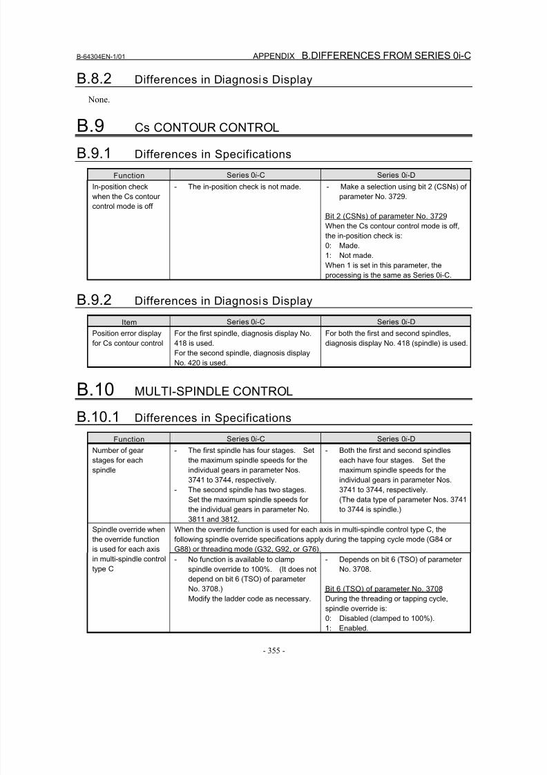
8/16/2019 Manual Operacion para FANUC
http://slidepdf.com/reader/full/manual-operacion-para-fanuc 373/435
B-64304EN-1/01 APPENDIX B.DIFFERENCES FROM SERIES 0i-C
- 355 -
B.8.2 Differences in Diagnosis Display
None.
B.9 Cs CONTOUR CONTROL
B.9.1 Differences in Specifications
Function Series 0i-C Series 0i-D
In-position check
when the Cs contour
control mode is off
- The in-position check is not made. - Make a selection using bit 2 (CSNs) of
parameter No. 3729.
Bit 2 (CSNs) of parameter No. 3729
When the Cs contour control mode is off,
the in-position check is:
0: Made.
1: Not made.
When 1 is set in this parameter, the
processing is the same as Series 0i-C.
B.9.2 Differences in Diagnosis Display
Item Series 0i-C Series 0i-D
Position error display
for Cs contour control
For the first spindle, diagnosis display No.
418 is used.
For the second spindle, diagnosis display
No. 420 is used.
For both the first and second spindles,
diagnosis display No. 418 (spindle) is used.
B.10 MULTI-SPINDLE CONTROL
B.10.1 Differences in Specifications
Function Series 0i-C Series 0i-D
Number of gear
stages for each
spindle
- The first spindle has four stages. Set
the maximum spindle speeds for the
individual gears in parameter Nos.
3741 to 3744, respectively.
- The second spindle has two stages.
Set the maximum spindle speeds for
the individual gears in parameter No.
3811 and 3812.
- Both the first and second spindles
each have four stages. Set the
maximum spindle speeds for the
individual gears in parameter Nos.
3741 to 3744, respectively.
(The data type of parameter Nos. 3741
to 3744 is spindle.)
When the override function is used for each axis in multi-spindle control type C, the
following spindle override specifications apply during the tapping cycle mode (G84 or
G88) or threading mode (G32, G92, or G76).
Spindle override when
the override function
is used for each axis
in multi-spindle control
type C
- No function is available to clamp
spindle override to 100%. (It does not
depend on bit 6 (TSO) of parameter
No. 3708.)
Modify the ladder code as necessary.
- Depends on bit 6 (TSO) of parameter
No. 3708.
Bit 6 (TSO) of parameter No. 3708
During the threading or tapping cycle,
spindle override is:0: Disabled (clamped to 100%).
1: Enabled.
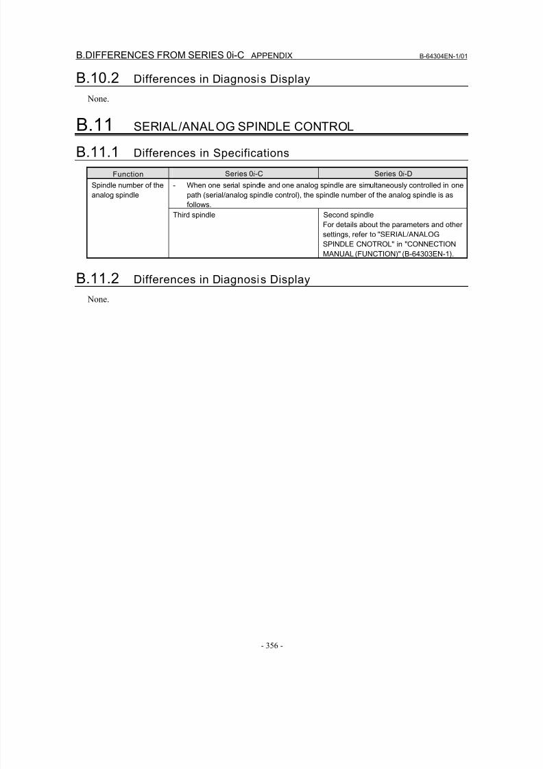
8/16/2019 Manual Operacion para FANUC
http://slidepdf.com/reader/full/manual-operacion-para-fanuc 374/435
B.DIFFERENCES FROM SERIES 0i-C APPENDIX B-64304EN-1/01
- 356 -
B.10.2 Differences in Diagnosis Display
None.
B.11 SERIAL/ANALOG SPINDLE CONTROL
B.11.1 Differences in Specifications
Function Series 0i-C Series 0i-D
- When one serial spindle and one analog spindle are simultaneously controlled in one
path (serial/analog spindle control), the spindle number of the analog spindle is as
follows.
Spindle number of the
analog spindle
Third spindle Second spindle
For details about the parameters and other
settings, refer to "SERIAL/ANALOG
SPINDLE CNOTROL" in "CONNECTION
MANUAL (FUNCTION)" (B-64303EN-1).
B.11.2 Differences in Diagnosis Display
None.
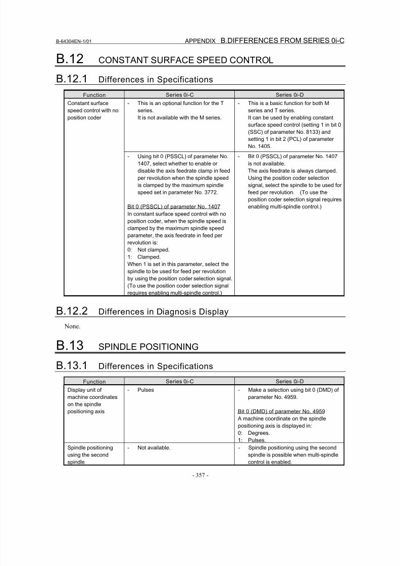
8/16/2019 Manual Operacion para FANUC
http://slidepdf.com/reader/full/manual-operacion-para-fanuc 375/435
B-64304EN-1/01 APPENDIX B.DIFFERENCES FROM SERIES 0i-C
- 357 -
B.12 CONSTANT SURFACE SPEED CONTROL
B.12.1 Differences in Specifications
Function Series 0i-C Series 0i-D
- This is an optional function for the T
series.
It is not available with the M series.
- This is a basic function for both M
series and T series.
It can be used by enabling constant
surface speed control (setting 1 in bit 0
(SSC) of parameter No. 8133) and
setting 1 in bit 2 (PCL) of parameter
No. 1405.
Constant surface
speed control with no
position coder
- Using bit 0 (PSSCL) of parameter No.
1407, select whether to enable or
disable the axis feedrate clamp in feed
per revolution when the spindle speedis clamped by the maximum spindle
speed set in parameter No. 3772.
Bit 0 (PSSCL) of parameter No. 1407
In constant surface speed control with no
position coder, when the spindle speed is
clamped by the maximum spindle speed
parameter, the axis feedrate in feed per
revolution is:
0: Not clamped.
1: Clamped.
When 1 is set in this parameter, select thespindle to be used for feed per revolution
by using the position coder selection signal.
(To use the position coder selection signal
requires enabling multi-spindle control.)
- Bit 0 (PSSCL) of parameter No. 1407
is not available.
The axis feedrate is always clamped.
Using the position coder selectionsignal, select the spindle to be used for
feed per revolution. (To use the
position coder selection signal requires
enabling multi-spindle control.)
B.12.2 Differences in Diagnosis Display
None.
B.13 SPINDLE POSITIONING
B.13.1 Differences in Specifications
Function Series 0i-C Series 0i-D
Display unit of
machine coordinates
on the spindle
positioning axis
- Pulses - Make a selection using bit 0 (DMD) of
parameter No. 4959.
Bit 0 (DMD) of parameter No. 4959
A machine coordinate on the spindle
positioning axis is displayed in:
0: Degrees.
1: Pulses.
Spindle positioning
using the second
spindle
- Not available. - Spindle positioning using the second
spindle is possible when multi-spindle
control is enabled.

8/16/2019 Manual Operacion para FANUC
http://slidepdf.com/reader/full/manual-operacion-para-fanuc 376/435
B.DIFFERENCES FROM SERIES 0i-C APPENDIX B-64304EN-1/01
- 358 -
Function Series 0i-C Series 0i-D
Number of M codes
for specifying the
spindle positioning
angle
- Make a selection using bit 6 (ESI) of
parameter No. 4950.
Bit 6 (ESI) of parameter No. 4950
Select the specification of spindle
positioning.
(Bit)
0: Standard specification.
1: Extended specification.
When the extended specification is
selected, the number of M codes for
specifying the spindle positioning angle can
be changed from 6 to any number in the
range of 1 to 255, depending on the setting
of parameter No. 4964.
- Regardless of the setting of bit 6 (ESI)
of parameter No. 4950, the setting of
parameter No. 4964 takes effect.
Rapid traverse rate
unit for spindlepositioning
- Selecting the extended specification by
setting 1 in bit 6 (ESI) of parameter No.4950 extends the upper limit of the
rapid traverse rate for spindle
positioning from 240000 to 269000
(unit: 10 degrees/min).
- Make a selection using bit 6 (ESI) of
parameter No. 4950.
Bit 6 (ESI) of parameter No. 4950
Select the rapid traverse rate unit for
spindle positioning (bit spindle).
0: Not increased by a factor of 10. (Unit:
degrees/min)
1: Increased by a factor of 10. (Unit:
10 degrees/min)
Rapid traverse rate for
spindle orientation in
the case of an analog
spindle
- The feedrate set in parameter No. 1420
takes effect.
- The feedrate set in parameter No.
1428 takes effect.
When 0 is set in parameter No. 1428,
the value set in parameter No. 1420takes effect.
B.13.2 Differences in Diagnosis Display
Item Series 0i-C Series 0i-D
Diagnosis data
indicating the spindle
positioning sequence
status (spindle)
- None. - Diagnosis No.1544
Diagnosis data
indicating the
clamp/unclamp
sequence status
(servo)
- None. - Diagnosis No.5207
B.14 TOOL FUNCTIONS
B.14.1 Differences in Specifications
Function Series 0i-C Series 0i-D
Specification of a G
code of the 00 groupother than G50 (T
series) and a T code
in the same block
- Not allowed. - Not allowed.
Specifying a G code in this way causesalarm PS0245.
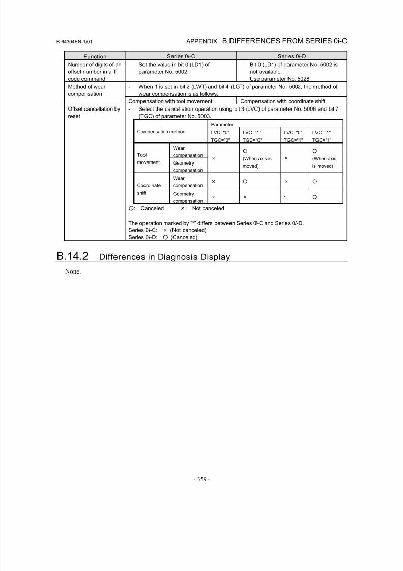
8/16/2019 Manual Operacion para FANUC
http://slidepdf.com/reader/full/manual-operacion-para-fanuc 377/435
B-64304EN-1/01 APPENDIX B.DIFFERENCES FROM SERIES 0i-C
- 359 -
Function Series 0i-C Series 0i-D
Number of digits of an
offset number in a T
code command
- Set the value in bit 0 (LD1) of
parameter No. 5002.
- Bit 0 (LD1) of parameter No. 5002 is
not available.
Use parameter No. 5028.
- When 1 is set in bit 2 (LWT) and bit 4 (LGT) of parameter No. 5002, the method of
wear compensation is as follows.
Method of wear
compensation
Compensation with tool movement Compensation with coordinate shift
Offset cancellation by
reset
- Select the cancellation operation using bit 3 (LVC) of parameter No. 5006 and bit 7
(TGC) of parameter No. 5003.
Parameter
Compensation method LVC="0"
TGC="0"
LVC="1"
TGC="0"
LVC="0"
TGC="1"
LVC="1"
TGC="1"
Wear
compensationTool
movement Geometry
compensation
×
○
(When axis is
moved)
×
○
(When axis
is moved)
Wearcompensation
× ○ × ○ Coordinate
shift Geometry
compensation× × * ○
○: Canceled ×: Not canceled
The operation marked by “*” differs between Series 0i-C and Series 0i-D.
Series 0i-C: × (Not canceled)
Series 0i-D: ○ (Canceled)
B.14.2 Differences in Diagnosis Display
None.
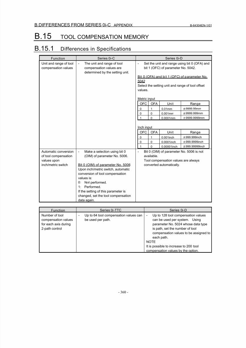
8/16/2019 Manual Operacion para FANUC
http://slidepdf.com/reader/full/manual-operacion-para-fanuc 378/435
B.DIFFERENCES FROM SERIES 0i-C APPENDIX B-64304EN-1/01
- 360 -
B.15 TOOL COMPENSATION MEMORY
B.15.1 Differences in Specifications
Function Series 0i-C Series 0i-D
Unit and range of tool
compensation values
- The unit and range of tool
compensation values are
determined by the setting unit.
- Set the unit and range using bit 0 (OFA) and
bit 1 (OFC) of parameter No. 5042.
Bit 0 (OFA) and bi t 1 (OFC) of parameter No.
5042
Select the setting unit and range of tool offset
values.
Metric input
OFC OFA Unit Range
0 1 0.01mm ±9999.99mm0 0 0.001mm ±9999.999mm
1 0 0.0001mm ±9999.9999mm
Inch input
OFC OFA Unit Range
0 1 0.001inch ±999.999inch
0 0 0.0001inch ±999.9999inch
1 0 0.00001inch ±999.99999inch
Automatic conversion
of tool compensation
values upon
inch/metric switch
- Make a selection using bit 0
(OIM) of parameter No. 5006.
Bit 0 (OIM) of parameter No. 5006Upon inch/metric switch, automatic
conversion of tool compensation
values is:
0: Not performed.
1: Performed.
If the setting of this parameter is
changed, set the tool compensation
data again.
- Bit 0 (OIM) of parameter No. 5006 is not
available.
Tool compensation values are always
converted automatically.
Function Series 0i-TTC Series 0i-D
Number of tool
compensation values
for each axis during
2-path control
- Up to 64 tool compensation values can
be used per path.
- Up to 128 tool compensation values
can be used per system. Using
parameter No. 5024 whose data type
is path, set the number of tool
compensation values to be assigned to
each path.
NOTE
It is possible to increase to 200 tool
compensation values by the option.
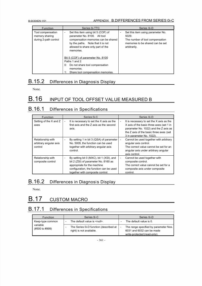
8/16/2019 Manual Operacion para FANUC
http://slidepdf.com/reader/full/manual-operacion-para-fanuc 379/435
B-64304EN-1/01 APPENDIX B.DIFFERENCES FROM SERIES 0i-C
- 361 -
Function Series 0i-TTC Series 0i-D
Tool compensation
memory sharing
during 2-path control
- Set this item using bit 5 (COF) of
parameter No. 8100. All tool
compensation memories can be shared
by the paths. Note that it is not
allowed to share only part of the
memories.
Bit 5 (COF) of parameter No. 8100
Paths 1 and 2:
0: Do not share tool compensation
memories.
1: Share tool compensation memories.
- Set this item using parameter No.
5029.
The number of tool compensation
memories to be shared can be set
arbitrarily.
B.15.2 Differences in Diagnosis Display
None.
B.16 INPUT OF TOOL OFFSET VALUE MEASURED B
B.16.1 Differences in Specifications
Function Series 0i-C Series 0i-D
Setting of the X and Z
axes
- It is necessary to set the X axis as the
first axis and the Z axis as the second
axis.
- It is necessary to set the X axis as the
X axis of the basic three axes (set 1 in
parameter No. 1022) and the Z axis as
the Z axis of the basic three axes (set
3 in parameter No. 1022).
Relationship with
arbitrary angular axis
control
- By setting 1 in bit 3 (QSA) of parameter
No. 5009, the function can be used
together with arbitrary angular axis
control.
- Cannot be used together with arbitrary
angular axis control.
The correct value cannot be set for an
angular axis under arbitrary angular
axis control.
Relationship with
composite control
- By setting bit 0 (MXC), bit 1 (XSI), and
bit 2 (ZSI) of parameter No. 8160 as
appropriate for the machine
configuration, the function can be used
together with composite control.
- Cannot be used together with
composite control.
The correct value cannot be set for a
composite axis under composite
control.
B.16.2 Differences in Diagnosis Display
None.
B.17 CUSTOM MACRO
B.17.1 Differences in Specifications
Function Series 0i-C Series 0i-D
- The default value is <null>. - The default value is 0.Keep-type common
variable(#500 to #999)
- The Series 0i-D function (described at
right) is not available.
- The range specified by parameter Nos.
6031 and 6032 can be made
write-protected (read-only).
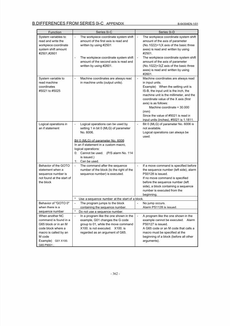
8/16/2019 Manual Operacion para FANUC
http://slidepdf.com/reader/full/manual-operacion-para-fanuc 380/435
B.DIFFERENCES FROM SERIES 0i-C APPENDIX B-64304EN-1/01
- 362 -
Function Series 0i-C Series 0i-D
System variables to
read and write the
workpiece coordinate
system shift amount
#2501,#2601
- The workpiece coordinate system shift
amount of the first axis is read and
written by using #2501.
- The workpiece coordinate system shift
amount of the second axis is read and
written by using #2601.
- The workpiece coordinate system shift
amount of the axis of parameter
(No.1022)=1(X axis of the basic three
axes) is read and written by using
#2501.
- The workpiece coordinate system shift
amount of the axis of parameter
(No.1022)=3(Z axis of the basic three
axes) is read and written by using
#2601.
System variable to
read machine
coordinates
#5021 to #5025
- Machine coordinates are always read
in machine units (output units).
- Machine coordinates are always read
in input units.
Example) When the setting unit is
IS-B, the input unit is the inch, the
machine unit is the millimeter, and the
coordinate value of the X axis (first
axis) is as follows:Machine coordinate = 30.000
(mm)
Since the value of #5021 is read in
input units (inches), #5021 is 1.1811.
Logical operations in
an if statement
- Logical operations can be used by
setting 1 in bit 0 (MLG) of parameter
No. 6006.
Bit 0 (MLG) of parameter No. 6006
In an if statement in a custom macro,
logical operations:
0: Cannot be used. (P/S alarm No. 114is issued.)
1: Can be used.
- Bit 0 (MLG) of parameter No. 6006 is
not available.
Logical operations can always be
used.
- The command after the sequence
number of the block (to the right of the
sequence number) is executed.
- If a move command is specified before
the sequence number (left side), alarm
PS0128 is issued.
If no move command is specified
before the sequence number (left
side), a block containing a sequence
number is executed from the
beginning.
Behavior of the GOTO
statement when a
sequence number is
not found at the start of
the block
* Use a sequence number at the start of a block.
- The program jumps to the block
containing the sequence number.
- No jump occurs.
Alarm PS1128 is issued.
Behavior of "GOTO 0"
when there is a
sequence number * Do not use a sequence number.
When another NC
command is found in a
G65 block or in an M
code block where a
macro is called by an
M code
Example) G01 X100.
G65 P9001 ;
- In a program like the one shown in the
example, G01 changes the G code
group to 01, while the move command
X100. is not executed. X100. is
regarded as an argument of G65.
- A program like the one shown in the
example cannot be executed. Alarm
PS0127 is issued.
A G65 code or an M code that calls a
macro must be specified at the
beginning of a block (before all other
arguments).
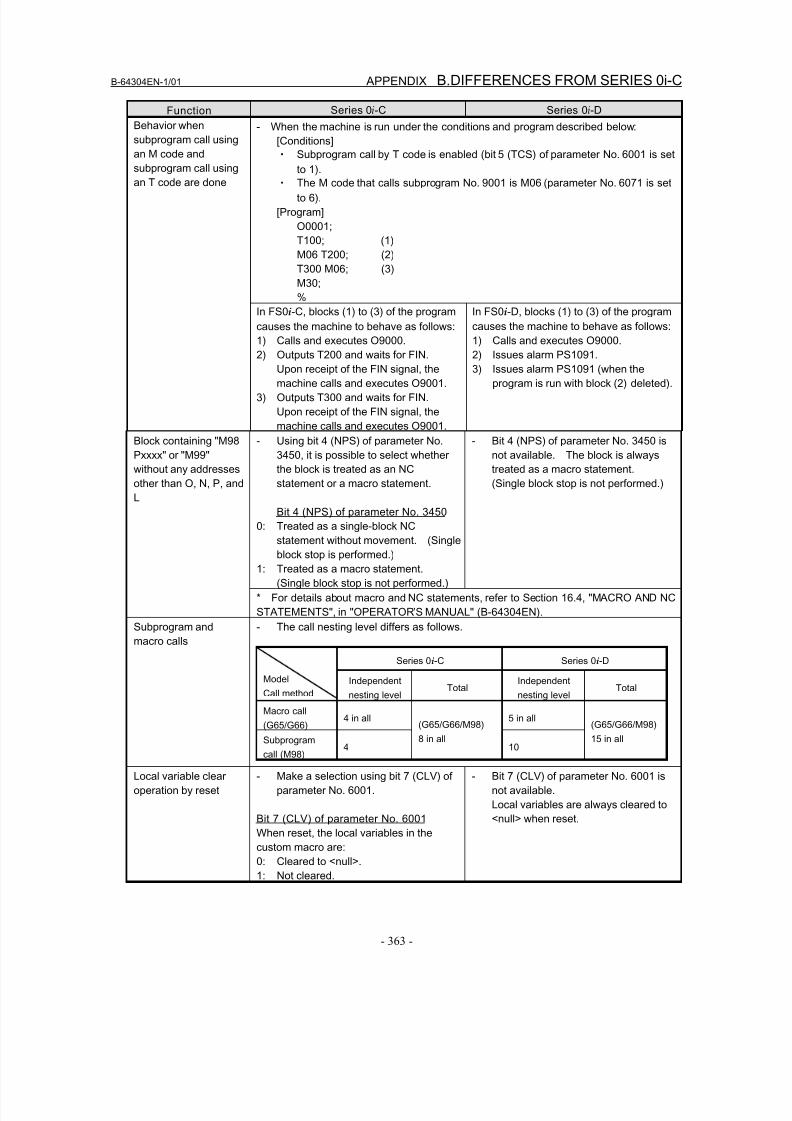
8/16/2019 Manual Operacion para FANUC
http://slidepdf.com/reader/full/manual-operacion-para-fanuc 381/435
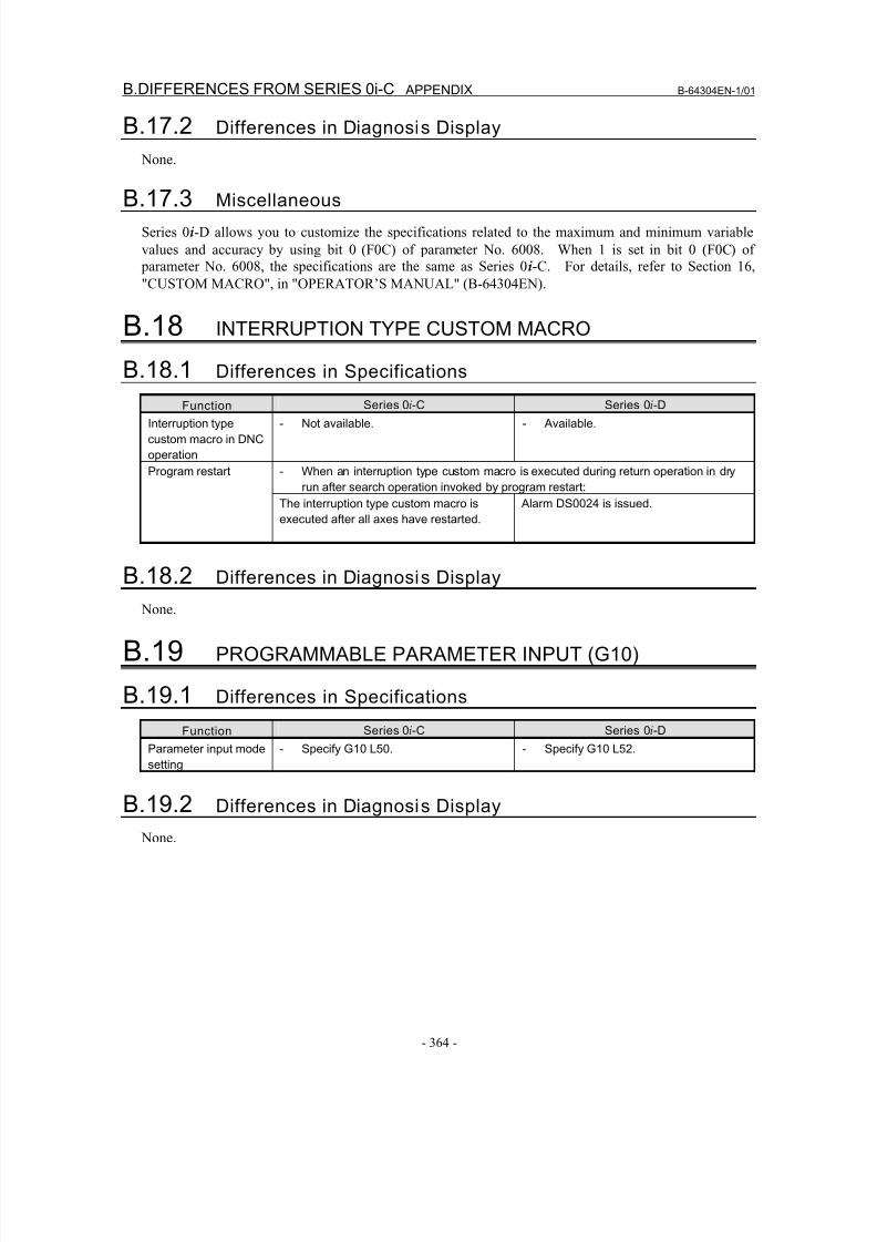
8/16/2019 Manual Operacion para FANUC
http://slidepdf.com/reader/full/manual-operacion-para-fanuc 382/435
B.DIFFERENCES FROM SERIES 0i-C APPENDIX B-64304EN-1/01
- 364 -
B.17.2 Differences in Diagnosis Display
None.
B.17.3 Miscellaneous
Series 0i-D allows you to customize the specifications related to the maximum and minimum variable
values and accuracy by using bit 0 (F0C) of parameter No. 6008. When 1 is set in bit 0 (F0C) of
parameter No. 6008, the specifications are the same as Series 0i-C. For details, refer to Section 16,
"CUSTOM MACRO", in "OPERATOR’S MANUAL" (B-64304EN).
B.18 INTERRUPTION TYPE CUSTOM MACRO
B.18.1 Differences in Specifications
Function Series 0i-C Series 0i-D
Interruption type
custom macro in DNC
operation
- Not available. - Available.
- When an interruption type custom macro is executed during return operation in dry
run after search operation invoked by program restart:
Program restart
The interruption type custom macro is
executed after all axes have restarted.
Alarm DS0024 is issued.
B.18.2 Differences in Diagnosis Display None.
B.19 PROGRAMMABLE PARAMETER INPUT (G10)
B.19.1 Differences in Specifications
Function Series 0i-C Series 0i-D
Parameter input mode
setting
- Specify G10 L50. - Specify G10 L52.
B.19.2 Differences in Diagnosis Display
None.
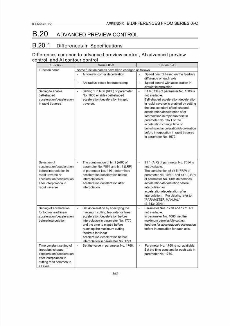
8/16/2019 Manual Operacion para FANUC
http://slidepdf.com/reader/full/manual-operacion-para-fanuc 383/435
B-64304EN-1/01 APPENDIX B.DIFFERENCES FROM SERIES 0i-C
- 365 -
B.20 ADVANCED PREVIEW CONTROL
B.20.1 Differences in Specifications
Differences common to advanced preview control , AI advanced previewcontrol, and AI contour control
Function Series 0i-C Series 0i-D
Some function names have been changed as follows.
- Automatic corner deceleration - Speed control based on the feedrate
difference on each axis
Function name
- Arc radius-based feedrate clamp - Speed control with acceleration in
circular interpolation
Setting to enable
bell-shaped
acceleration/deceleration
in rapid traverse
- Setting 1 in bit 6 (RBL) of parameter
No. 1603 enables bell-shaped
acceleration/deceleration in rapid
traverse.
- Bit 6 (RBL) of parameter No. 1603 is
not available.
Bell-shaped acceleration/deceleration
in rapid traverse is enabled by setting
the time constant of bell-shaped
acceleration/deceleration after
interpolation in rapid traverse in
parameter No. 1621 or the
acceleration change time of
bell-shaped acceleration/deceleration
before interpolation in rapid traverse
in parameter No. 1672.
Selection of
acceleration/deceleration
before interpolation in
rapid traverse or
acceleration/deceleration
after interpolation in
rapid traverse
- The combination of bit 1 (AIR) of
parameter No. 7054 and bit 1 (LRP)
of parameter No. 1401 determines
acceleration/deceleration before
interpolation or
acceleration/deceleration after
interpolation.
- Bit 1 (AIR) of parameter No. 7054 is
not available.
The combination of bit 5 (FRP) of
parameter No. 19501 and bit 1 (LRP)
of parameter No. 1401 determines
acceleration/deceleration before
interpolation or
acceleration/deceleration after
interpolation. For details, refer to
"PARAMETER MANUAL"
(B-64310EN).Setting of acceleration
for look-ahead linear
acceleration/deceleration
before interpolation
- Set acceleration by specifying the
maximum cutting feedrate for linear
acceleration/deceleration before
interpolation in parameter No. 1770
and the time to elapse before
reaching the maximum cutting
feedrate for linear
acceleration/deceleration before
interpolation in parameter No. 1771.
- Parameter Nos. 1770 and 1771 are
not available.
In parameter No. 1660, set the
maximum permissible cutting
feedrate for acceleration/deceleration
before interpolation for each axis.
Time constant setting of
linear/bell-shaped
acceleration/deceleration
after interpolation in
cutting feed common to
all axes
- Set the value in parameter No. 1768. - Parameter No. 1768 is not available.
Set the time constant for each axis in
parameter No. 1769.
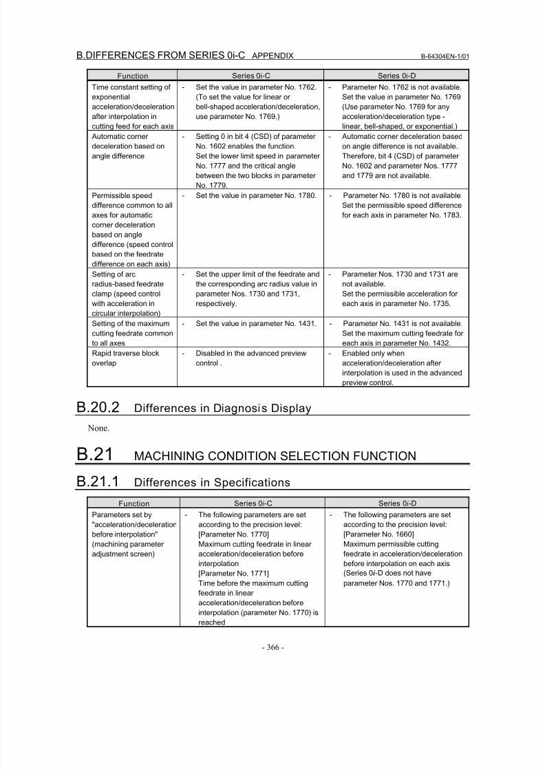
8/16/2019 Manual Operacion para FANUC
http://slidepdf.com/reader/full/manual-operacion-para-fanuc 384/435
B.DIFFERENCES FROM SERIES 0i-C APPENDIX B-64304EN-1/01
- 366 -
Function Series 0i-C Series 0i-D
Time constant setting of
exponential
acceleration/deceleration
after interpolation in
cutting feed for each axis
- Set the value in parameter No. 1762.
(To set the value for linear or
bell-shaped acceleration/deceleration,
use parameter No. 1769.)
- Parameter No. 1762 is not available.
Set the value in parameter No. 1769.
(Use parameter No. 1769 for any
acceleration/deceleration type -
linear, bell-shaped, or exponential.)
Automatic corner
deceleration based on
angle difference
- Setting 0 in bit 4 (CSD) of parameter
No. 1602 enables the function.
Set the lower limit speed in parameter
No. 1777 and the critical angle
between the two blocks in parameter
No. 1779.
- Automatic corner deceleration based
on angle difference is not available.
Therefore, bit 4 (CSD) of parameter
No. 1602 and parameter Nos. 1777
and 1779 are not available.
Permissible speed
difference common to all
axes for automatic
corner deceleration
based on angle
difference (speed control
based on the feedrate
difference on each axis)
- Set the value in parameter No. 1780. - Parameter No. 1780 is not available.
Set the permissible speed difference
for each axis in parameter No. 1783.
Setting of arc
radius-based feedrate
clamp (speed control
with acceleration in
circular interpolation)
- Set the upper limit of the feedrate and
the corresponding arc radius value in
parameter Nos. 1730 and 1731,
respectively.
- Parameter Nos. 1730 and 1731 are
not available.
Set the permissible acceleration for
each axis in parameter No. 1735.
Setting of the maximum
cutting feedrate common
to all axes
- Set the value in parameter No. 1431. - Parameter No. 1431 is not available.
Set the maximum cutting feedrate for
each axis in parameter No. 1432.
Rapid traverse block
overlap
- Disabled in the advanced preview
control .
- Enabled only when
acceleration/deceleration afterinterpolation is used in the advanced
preview control.
B.20.2 Differences in Diagnosis Display
None.
B.21 MACHINING CONDITION SELECTION FUNCTION
B.21.1 Differences in SpecificationsFunction Series 0i-C Series 0i-D
Parameters set by
"acceleration/deceleration
before interpolation"
(machining parameter
adjustment screen)
- The following parameters are set
according to the precision level:
[Parameter No. 1770]
Maximum cutting feedrate in linear
acceleration/deceleration before
interpolation
[Parameter No. 1771]
Time before the maximum cutting
feedrate in linear
acceleration/deceleration beforeinterpolation (parameter No. 1770) is
reached
- The following parameters are set
according to the precision level:
[Parameter No. 1660]
Maximum permissible cutting
feedrate in acceleration/deceleration
before interpolation on each axis
(Series 0i-D does not have
parameter Nos. 1770 and 1771.)
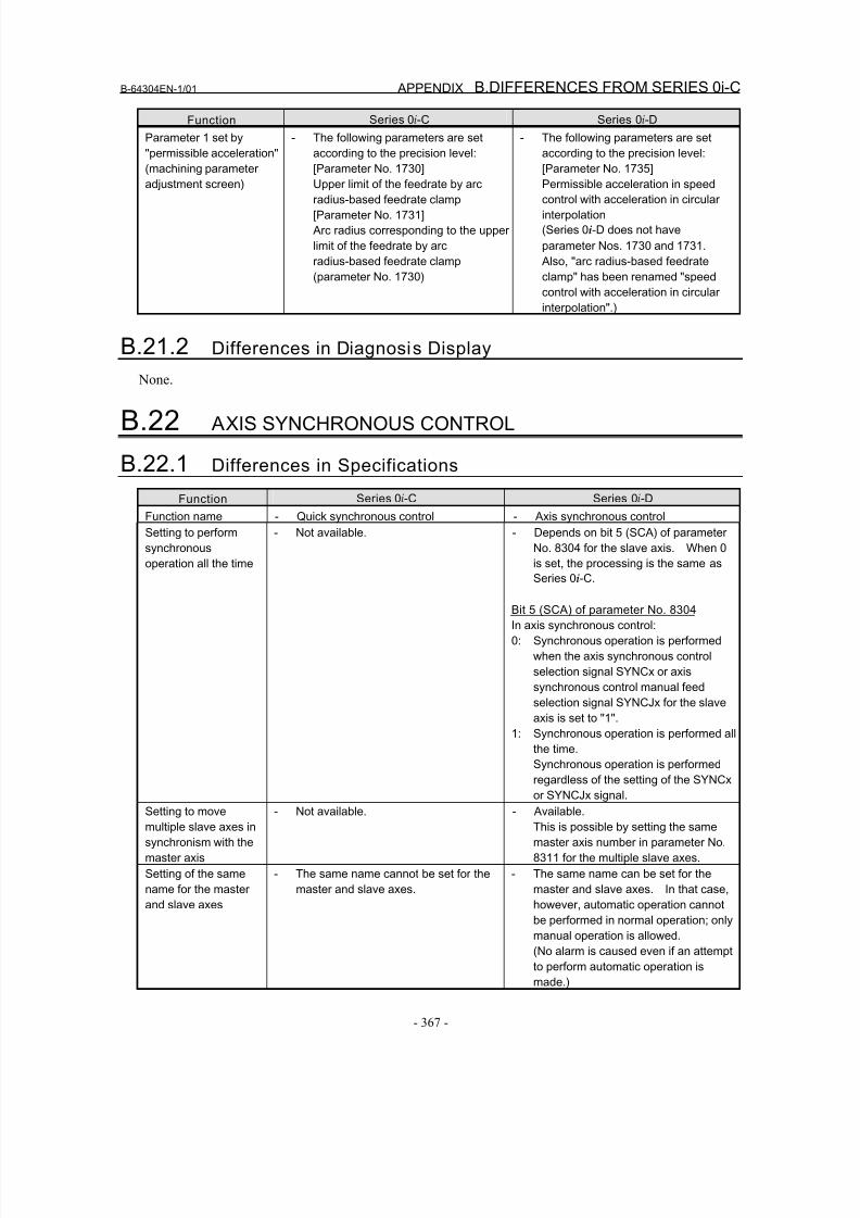
8/16/2019 Manual Operacion para FANUC
http://slidepdf.com/reader/full/manual-operacion-para-fanuc 385/435
B-64304EN-1/01 APPENDIX B.DIFFERENCES FROM SERIES 0i-C
- 367 -
Function Series 0i-C Series 0i-D
Parameter 1 set by
"permissible acceleration"
(machining parameter
adjustment screen)
- The following parameters are set
according to the precision level:
[Parameter No. 1730]
Upper limit of the feedrate by arc
radius-based feedrate clamp
[Parameter No. 1731]
Arc radius corresponding to the upper
limit of the feedrate by arc
radius-based feedrate clamp
(parameter No. 1730)
- The following parameters are set
according to the precision level:
[Parameter No. 1735]
Permissible acceleration in speed
control with acceleration in circular
interpolation
(Series 0i-D does not have
parameter Nos. 1730 and 1731.
Also, "arc radius-based feedrate
clamp" has been renamed "speed
control with acceleration in circular
interpolation".)
B.21.2 Differences in Diagnosis Display
None.
B.22 AXIS SYNCHRONOUS CONTROL
B.22.1 Differences in Specifications
Function Series 0i-C Series 0i-D
Function name - Quick synchronous control - Axis synchronous control
Setting to perform
synchronous
operation all the time
- Not available. - Depends on bit 5 (SCA) of parameter
No. 8304 for the slave axis. When 0
is set, the processing is the same as
Series 0i-C.
Bit 5 (SCA) of parameter No. 8304
In axis synchronous control:
0: Synchronous operation is performed
when the axis synchronous control
selection signal SYNCx or axis
synchronous control manual feed
selection signal SYNCJx for the slave
axis is set to "1".
1: Synchronous operation is performed all
the time.
Synchronous operation is performedregardless of the setting of the SYNCx
or SYNCJx signal.
Setting to move
multiple slave axes in
synchronism with the
master axis
- Not available. - Available.
This is possible by setting the same
master axis number in parameter No.
8311 for the multiple slave axes.
Setting of the same
name for the master
and slave axes
- The same name cannot be set for the
master and slave axes.
- The same name can be set for the
master and slave axes. In that case,
however, automatic operation cannot
be performed in normal operation; only
manual operation is allowed.
(No alarm is caused even if an attemptto perform automatic operation is
made.)
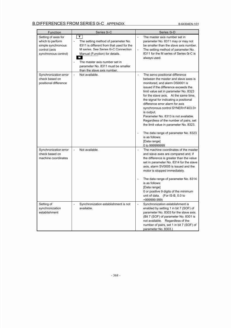
8/16/2019 Manual Operacion para FANUC
http://slidepdf.com/reader/full/manual-operacion-para-fanuc 386/435
B.DIFFERENCES FROM SERIES 0i-C APPENDIX B-64304EN-1/01
- 368 -
Function Series 0i-C Series 0i-D
Setting of axes for
which to perform
simple synchronous
control (axis
synchronous control)
T
- The setting method of parameter No.
8311 is different from that used for the
M series. See Series 0i-C Connection
Manual (Function) for details.
- The master axis number set in
parameter No. 8311 must be smaller
than the slave axis number.
- The master axis number set in
parameter No. 8311 may or may not
be smaller than the slave axis number.
- The setting method of parameter No.
8311 for the M series of Series 0i-C is
always used.
Synchronization error
check based on
positional difference
- Not available. - The servo positional difference
between the master and slave axes is
monitored, and alarm DS0001 is
issued if the difference exceeds the
limit value set in parameter No. 8323
for the slave axis. At the same time,
the signal for indicating a positional
difference error alarm for axissynchronous control SYNER<F403.0>
is output.
Parameter No. 8313 is not available.
Regardless of the number of pairs, set
the limit value in parameter No. 8323.
- The data range of parameter No. 8323
is as follows:
[Data range]
0 to 999999999
Synchronization error
check based onmachine coordinates
- Not available. - The machine coordinates of the master
and slave axes are compared and, ifthe difference is greater than the value
set in parameter No. 8314 for the slave
axis, alarm SV0005 is issued and the
motor is stopped immediately.
- The data range of parameter No. 8314
is as follows:
[Data range]
0 or positive 9 digits of the minimum
unit of data. (For IS-B, 0.0 to
+999999.999)
Setting of
synchronization
establishment
- Synchronization establishment is not
available.
- Synchronization establishment is
enabled by setting 1 in bit 7 (SOF) of
parameter No. 8303 for the slave axis.
(Bit 7 (SOF) of parameter No. 8301 is
not available. Regardless of the
number of pairs, set 1 in bit 7 (SOF) of
parameter No. 8303.)
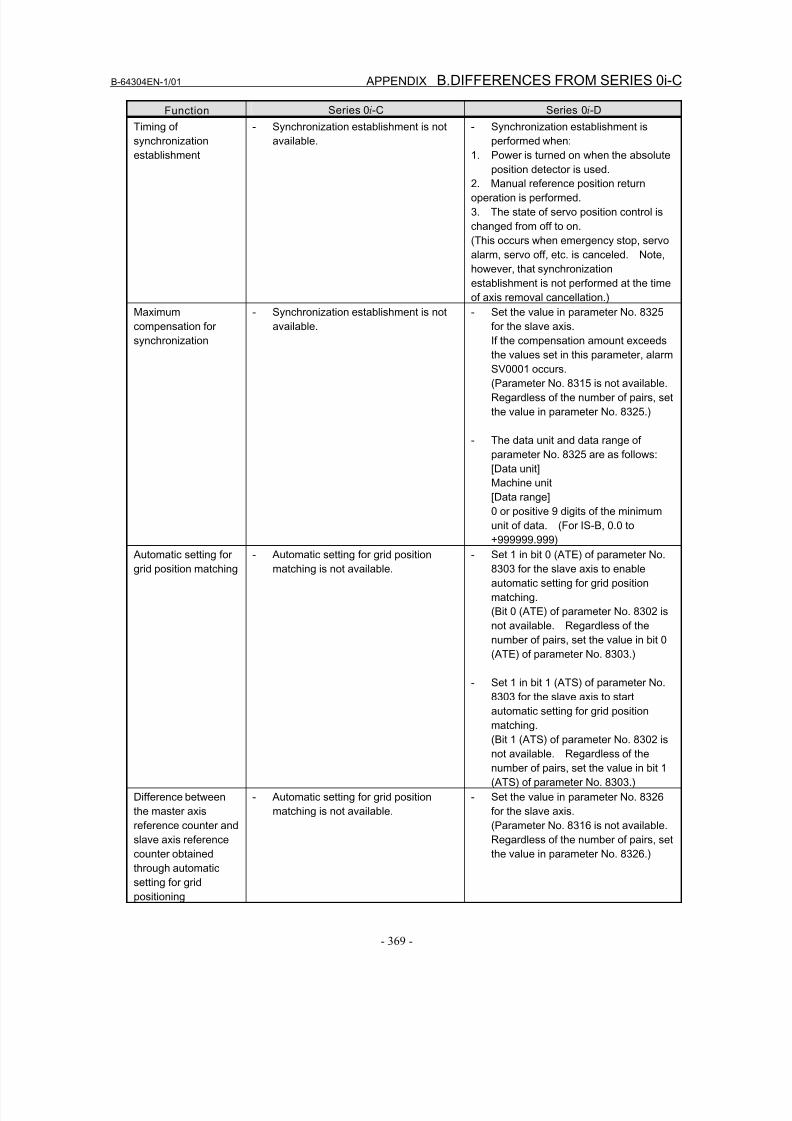
8/16/2019 Manual Operacion para FANUC
http://slidepdf.com/reader/full/manual-operacion-para-fanuc 387/435
B-64304EN-1/01 APPENDIX B.DIFFERENCES FROM SERIES 0i-C
- 369 -
Function Series 0i-C Series 0i-D
Timing of
synchronization
establishment
- Synchronization establishment is not
available.
- Synchronization establishment is
performed when:
1. Power is turned on when the absolute
position detector is used.
2. Manual reference position return
operation is performed.
3. The state of servo position control is
changed from off to on.
(This occurs when emergency stop, servo
alarm, servo off, etc. is canceled. Note,
however, that synchronization
establishment is not performed at the time
of axis removal cancellation.)
Maximum
compensation for
synchronization
- Synchronization establishment is not
available.
- Set the value in parameter No. 8325
for the slave axis.
If the compensation amount exceeds
the values set in this parameter, alarmSV0001 occurs.
(Parameter No. 8315 is not available.
Regardless of the number of pairs, set
the value in parameter No. 8325.)
- The data unit and data range of
parameter No. 8325 are as follows:
[Data unit]
Machine unit
[Data range]
0 or positive 9 digits of the minimum
unit of data. (For IS-B, 0.0 to+999999.999)
Automatic setting for
grid position matching
- Automatic setting for grid position
matching is not available.
- Set 1 in bit 0 (ATE) of parameter No.
8303 for the slave axis to enable
automatic setting for grid position
matching.
(Bit 0 (ATE) of parameter No. 8302 is
not available. Regardless of the
number of pairs, set the value in bit 0
(ATE) of parameter No. 8303.)
- Set 1 in bit 1 (ATS) of parameter No.
8303 for the slave axis to start
automatic setting for grid position
matching.
(Bit 1 (ATS) of parameter No. 8302 is
not available. Regardless of the
number of pairs, set the value in bit 1
(ATS) of parameter No. 8303.)
Difference between
the master axis
reference counter and
slave axis reference
counter obtained
through automatic
setting for gridpositioning
- Automatic setting for grid position
matching is not available.
- Set the value in parameter No. 8326
for the slave axis.
(Parameter No. 8316 is not available.
Regardless of the number of pairs, set
the value in parameter No. 8326.)
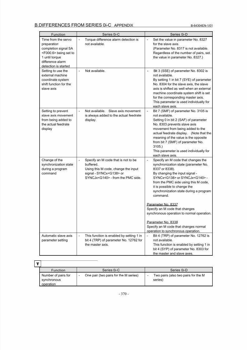
8/16/2019 Manual Operacion para FANUC
http://slidepdf.com/reader/full/manual-operacion-para-fanuc 388/435
B.DIFFERENCES FROM SERIES 0i-C APPENDIX B-64304EN-1/01
- 370 -
Function Series 0i-C Series 0i-D
Time from the servo
preparation
completion signal SA
<F000.6> being set to
1 until torque
difference alarm
detection is started
- Torque difference alarm detection is
not available.
- Set the value in parameter No. 8327
for the slave axis.
(Parameter No. 8317 is not available.
Regardless of the number of pairs, set
the value in parameter No. 8327.)
Setting to use the
external machine
coordinate system
shift function for the
slave axis
- Not available. - Bit 3 (SSE) of parameter No. 8302 is
not available.
By setting 1 in bit 7 (SYE) of parameter
No. 8304 for the slave axis, the slave
axis is shifted as well when an external
machine coordinate system shift is set
for the corresponding master axis.
This parameter is used individually for
each slave axis.
Setting to prevent
slave axis movement
from being added to
the actual feedrate
display
- Not available. Slave axis movement
is always added to the actual feedrate
display.
- Bit 7 (SMF) of parameter No. 3105 is
not available.
Setting 0 in bit 2 (SAF) of parameter
No. 8303 prevents slave axis
movement from being added to the
actual feedrate display. (Note that the
meaning of the value is the opposite
from bit 7 (SMF) of parameter No.
3105.)
This parameter is used individually for
each slave axis.
Change of the
synchronization stateduring a program
command
- Specify an M code that is not to be
buffered.Using this M code, change the input
signal - SYNCx<G138> or
SYNCJx<G140> - from the PMC side.
- Specify an M code that changes the
synchronization state (parameter No.8337 or 8338).
By changing the input signal -
SYNCx<G138> or SYNCJx<G140> -
from the PMC side using this M code,
it is possible to change the
synchronization state during a program
command.
Parameter No. 8337
Specify an M code that changes
synchronous operation to normal operation.
Parameter No. 8338
Specify an M code that changes normal
operation to synchronous operation.
Automatic slave axis
parameter setting
- This function is enabled by setting 1 in
bit 4 (TRP) of parameter No. 12762 for
the master axis.
- Bit 4 (TRP) of parameter No. 12762 is
not available.
This function is enabled by setting 1 in
bit 4 (SYP) of parameter No. 8303 for
the master and slave axes.
T Function Series 0i-C Series 0i-D
Number of pairs forsynchronous
operation
- One pair (two pairs for the M series) - Two pairs (also two pairs for the Mseries)
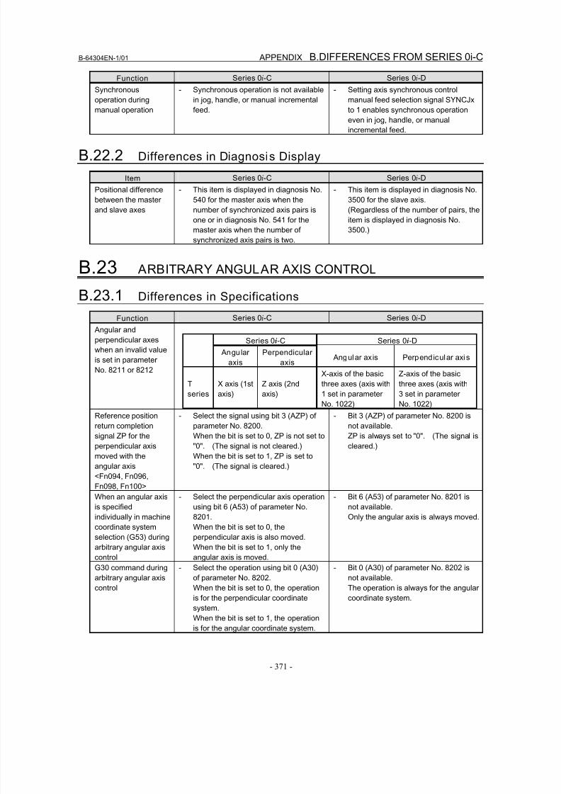
8/16/2019 Manual Operacion para FANUC
http://slidepdf.com/reader/full/manual-operacion-para-fanuc 389/435
B-64304EN-1/01 APPENDIX B.DIFFERENCES FROM SERIES 0i-C
- 371 -
Function Series 0i-C Series 0i-D
Synchronous
operation during
manual operation
- Synchronous operation is not available
in jog, handle, or manual incremental
feed.
- Setting axis synchronous control
manual feed selection signal SYNCJx
to 1 enables synchronous operation
even in jog, handle, or manual
incremental feed.
B.22.2 Differences in Diagnosis Display
Item Series 0i-C Series 0i-D
Positional difference
between the master
and slave axes
- This item is displayed in diagnosis No.
540 for the master axis when the
number of synchronized axis pairs is
one or in diagnosis No. 541 for the
master axis when the number of
synchronized axis pairs is two.
- This item is displayed in diagnosis No.
3500 for the slave axis.
(Regardless of the number of pairs, the
item is displayed in diagnosis No.
3500.)
B.23 ARBITRARY ANGULAR AXIS CONTROL
B.23.1 Differences in Specifications
Function Series 0i-C Series 0i-D
Angular and
perpendicular axes
when an invalid value
is set in parameter
No. 8211 or 8212
Series 0i-C Series 0i-D
Angular
axis
Perpendicular
axis Angular axis Perpendicular axis
T
series
X axis (1st
axis)
Z axis (2nd
axis)
X-axis of the basicthree axes (axis with
1 set in parameter
No. 1022)
Z-axis of the basicthree axes (axis with
3 set in parameter
No. 1022)
Reference position
return completion
signal ZP for the
perpendicular axis
moved with the
angular axis
<Fn094, Fn096,
Fn098, Fn100>
- Select the signal using bit 3 (AZP) of
parameter No. 8200.
When the bit is set to 0, ZP is not set to
"0". (The signal is not cleared.)
When the bit is set to 1, ZP is set to
"0". (The signal is cleared.)
- Bit 3 (AZP) of parameter No. 8200 is
not available.
ZP is always set to "0". (The signal is
cleared.)
When an angular axisis specified
individually in machine
coordinate system
selection (G53) during
arbitrary angular axis
control
- Select the perpendicular axis operationusing bit 6 (A53) of parameter No.
8201.
When the bit is set to 0, the
perpendicular axis is also moved.
When the bit is set to 1, only the
angular axis is moved.
- Bit 6 (A53) of parameter No. 8201 isnot available.
Only the angular axis is always moved.
G30 command during
arbitrary angular axis
control
- Select the operation using bit 0 (A30)
of parameter No. 8202.
When the bit is set to 0, the operation
is for the perpendicular coordinate
system.
When the bit is set to 1, the operation
is for the angular coordinate system.
- Bit 0 (A30) of parameter No. 8202 is
not available.
The operation is always for the angular
coordinate system.
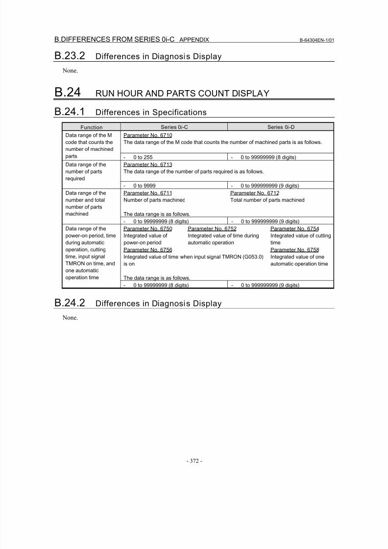
8/16/2019 Manual Operacion para FANUC
http://slidepdf.com/reader/full/manual-operacion-para-fanuc 390/435
B.DIFFERENCES FROM SERIES 0i-C APPENDIX B-64304EN-1/01
- 372 -
B.23.2 Differences in Diagnosis Display
None.
B.24 RUN HOUR AND PARTS COUNT DISPLAY
B.24.1 Differences in Specifications
Function Series 0i-C Series 0i-D
Parameter No. 6710
The data range of the M code that counts the number of machined parts is as follows.
Data range of the M
code that counts the
number of machined
parts - 0 to 255 - 0 to 99999999 (8 digits)
Parameter No. 6713
The data range of the number of parts required is as follows.
Data range of the
number of partsrequired
- 0 to 9999 - 0 to 999999999 (9 digits)
Parameter No. 6711
Number of parts machined
Parameter No. 6712
Total number of parts machined
The data range is as follows.
Data range of the
number and total
number of parts
machined
- 0 to 99999999 (8 digits) - 0 to 999999999 (9 digits)
Parameter No. 6750
Integrated value of
power-on period
Parameter No. 6752
Integrated value of time during
automatic operation
Parameter No. 6754
Integrated value of cutting
time
Parameter No. 6756
Integrated value of time when input signal TMRON (G053.0)is on
Parameter No. 6758
Integrated value of oneautomatic operation time
The data range is as follows.
Data range of the
power-on period, time
during automatic
operation, cutting
time, input signalTMRON on time, and
one automatic
operation time
- 0 to 99999999 (8 digits) - 0 to 999999999 (9 digits)
B.24.2 Differences in Diagnosis Display
None.
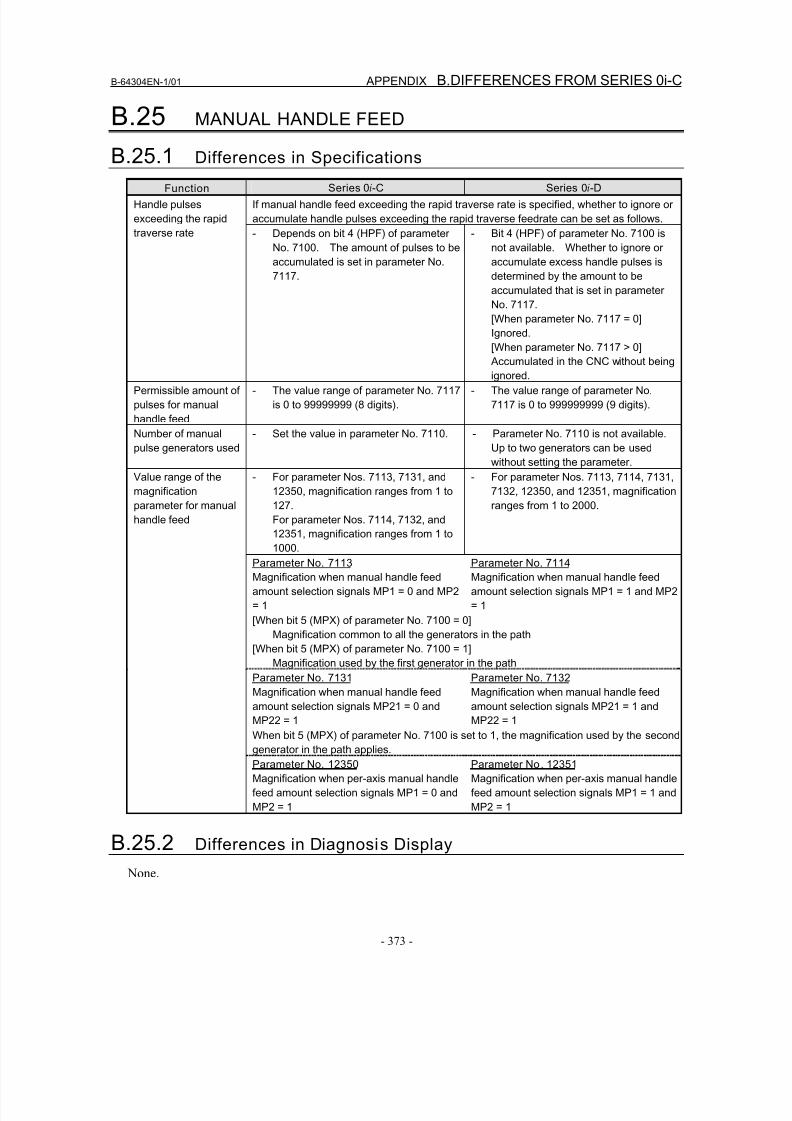
8/16/2019 Manual Operacion para FANUC
http://slidepdf.com/reader/full/manual-operacion-para-fanuc 391/435
B-64304EN-1/01 APPENDIX B.DIFFERENCES FROM SERIES 0i-C
- 373 -
B.25 MANUAL HANDLE FEED
B.25.1 Differences in Specifications
Function Series 0i-C Series 0i-D
If manual handle feed exceeding the rapid traverse rate is specified, whether to ignore or
accumulate handle pulses exceeding the rapid traverse feedrate can be set as follows.
Handle pulses
exceeding the rapid
traverse rate - Depends on bit 4 (HPF) of parameter
No. 7100. The amount of pulses to be
accumulated is set in parameter No.
7117.
- Bit 4 (HPF) of parameter No. 7100 is
not available. Whether to ignore or
accumulate excess handle pulses is
determined by the amount to be
accumulated that is set in parameter
No. 7117.
[When parameter No. 7117 = 0]
Ignored.
[When parameter No. 7117 > 0] Accumulated in the CNC without being
ignored.
Permissible amount of
pulses for manual
handle feed
- The value range of parameter No. 7117
is 0 to 99999999 (8 digits).
- The value range of parameter No.
7117 is 0 to 999999999 (9 digits).
Number of manual
pulse generators used
- Set the value in parameter No. 7110. - Parameter No. 7110 is not available.
Up to two generators can be used
without setting the parameter.
- For parameter Nos. 7113, 7131, and
12350, magnification ranges from 1 to
127.
For parameter Nos. 7114, 7132, and
12351, magnification ranges from 1 to
1000.
- For parameter Nos. 7113, 7114, 7131,
7132, 12350, and 12351, magnification
ranges from 1 to 2000.
Parameter No. 7113
Magnification when manual handle feed
amount selection signals MP1 = 0 and MP2
= 1
Parameter No. 7114
Magnification when manual handle feed
amount selection signals MP1 = 1 and MP2
= 1
[When bit 5 (MPX) of parameter No. 7100 = 0]
Magnification common to all the generators in the path
[When bit 5 (MPX) of parameter No. 7100 = 1]
Magnification used by the first generator in the path
Parameter No. 7131
Magnification when manual handle feed
amount selection signals MP21 = 0 andMP22 = 1
Parameter No. 7132
Magnification when manual handle feed
amount selection signals MP21 = 1 andMP22 = 1
When bit 5 (MPX) of parameter No. 7100 is set to 1, the magnification used by the second
generator in the path applies.
Value range of the
magnification
parameter for manual
handle feed
Parameter No. 12350
Magnification when per-axis manual handle
feed amount selection signals MP1 = 0 and
MP2 = 1
Parameter No. 12351
Magnification when per-axis manual handle
feed amount selection signals MP1 = 1 and
MP2 = 1
B.25.2 Differences in Diagnosis Display
None.
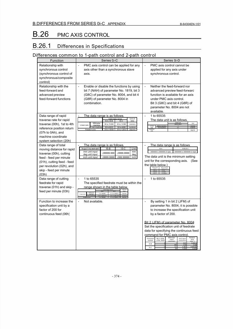
8/16/2019 Manual Operacion para FANUC
http://slidepdf.com/reader/full/manual-operacion-para-fanuc 392/435
B.DIFFERENCES FROM SERIES 0i-C APPENDIX B-64304EN-1/01
- 374 -
B.26 PMC AXIS CONTROL
B.26.1 Differences in Specifications
Differences common to 1-path control and 2-path controlFunction Series 0i-C Series 0i-D
Relationship with
synchronous control
(synchronous control of
synchronous/composite
control)
- PMC axis control can be applied for any
axis other than a synchronous slave
axis.
- PMC axis control cannot be
applied for any axis under
synchronous control.
Relationship with the
feed-forward and
advanced preview
feed-forward functions
- Enable or disable the functions by using
bit 7 (NAH) of parameter No. 1819, bit 3
(G8C) of parameter No. 8004, and bit 4
(G8R) of parameter No. 8004 in
combination.
- Neither the feed-forward nor
advanced preview feed-forward
function is available for an axis
under PMC axis control.
Bit 3 (G8C) and bit 4 (G8R) ofparameter No. 8004 are not
available.
Data range of rapid
traverse rate for rapid
traverse (00h), 1st to 4th
reference position return
(07h to 0Ah), and
machine coordinate
system selection (20h)
- The data range is as follows.Valid data range
IS-A, IS-B IS-C
Unit ofdata
Millimetermachine
30 to 15 000 30 to 12 000 mm/mi nLinear axis
Inch machine 30 to 6000 30 to 4800 inch/min
Rotat ion axis 30 to 15000 30 to 12000 deg/min
- 1 to 65535
The data unit is as follows.Data unit
IS-A to IS-CUnit
Metric machine 1 mm/minLinearaxis Inch machine 0.1 inch/min
Rotationaxis
1 deg/min
Data range of total
moving distance for rapid
traverse (00h), cuttingfeed - feed per minute
(01h), cutting feed - feed
per revolution (02h), and
skip - feed per minute
(03h)
- The data range is as follows.Inpu t i nc rem en t IS-B IS-C U ni t
mm unit input
deg unit input
±99999.999 ±9999.9999mm
deginch unit input ±9999.9999 ±999.99999 inch
- The data range is as follows.IS-A IS-B,IS-C
-99999999 to 99999999 (8 digits) -999999999 to 999999999 (9 digits)
The data unit is the minimum setting
unit for the corresponding axis. (See
the table below.)S e t t i n g
u n i tM i n i m u md a t a u n i t
I S - A 0 . 0 1I S - B 0 . 0 0 1I S - C 0 . 0 0 0 1
Data range of cutting
feedrate for rapid
traverse (01h) and skip -
feed per minute (03h)
- 1 to 65535
The specified feedrate must be within the
range shown in the table below.Valid data range
IS-B IS-CUnit ofdata
Millimetermachine
1 to 100000 0.1 to 12000.0 mm/minLinear axis
Inch machine 0.01 to 4000.00 0.01 to 480.000 inch/min
Rotation axis 1 to 100000 0.1 to 12000.0 deg/min
- 1 to 65535
Function to increase the
specification unit by afactor of 200 for
continuous feed (06h)
- Not available. - By setting 1 in bit 2 (JFM) of
parameter No. 8004, it is possibleto increase the specification unit
by a factor of 200.
Bit 2 (JFM) of parameter No. 8004
Set the specification unit of feedrate
data for specifying the continuous feed
command for PMC axis control.Increment
systemBit 2 (JFM)of No. 8004
Millimeterinput
(mm/min)
Inch input(inch/min)
Rotationaxis
(min-1
)
0 1 0.01 0.00023IS-B
1 200 2.00 0.046
0 0.1 0. 001 0.000 023IS-C
1 20 0.200 0.0046
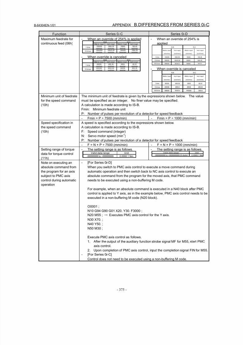
8/16/2019 Manual Operacion para FANUC
http://slidepdf.com/reader/full/manual-operacion-para-fanuc 393/435
B-64304EN-1/01 APPENDIX B.DIFFERENCES FROM SERIES 0i-C
- 375 -
Function Series 0i-C Series 0i-D
Maximum feedrate for
continuous feed (06h)
- When an override of 254% is appliedIS-B IS-C
Met r ic inpu t Inch inpu t Met r ic inpu t Inch inpu t
1 time166458mm/min
1664.58inch/min
16645mm/min
166.45inch/min
10 times1664589mm/min
16645.89inch/min
1664580mm/min
1664.58inch/min
- When override is canceledIS-B IS-C
Met r ic inpu t Inch inpu t Met r ic inpu t Inch inpu t
1 time65535
mm/min655.35
inch/min6553
mm/min65.53
inch/min
10 times655350mm/min
6553.50inch/min
65535mm/min
655.35inch/min
- When an override of 254% is
appliedIS-B IS-C
Metric input
(mm/min)
Inch input
(inch/min)
Metric input
(mm/min)
Inch input
(inch/min)
1 time 166458 1664.58 16645 166.46
10 times 999000 16645.89 99900 1664.58
200 times 999000 39330.0 99900 3933.0
- When override is canceledIS-B IS-C
Metric input
(mm/min)
Inch input
(inch/min)
Metric input
(mm/min)
Inch input
(inch/min)
1 time 65535 655.35 6553 65.53
10 times 655350 6553.5 65535 655.35
200 times 999000 39330.0 999000 3933.0
The minimum unit of feedrate is given by the expressions shown below. The value
must be specified as an integer. No finer value may be specified.
A calculation is made according to IS-B.
Fmin: Minimum feedrate unit
P: Number of pulses per revolution of a detector for speed feedback
Minimum unit of feedrate
for the speed command
(10h)
- Fmin = P ÷ 7500 (mm/min) - Fmin = P ÷ 1000 (mm/min)
A speed is specified according to the expressions shown below.
A calculation is made according to IS-B.
F: Speed command (integer)
N: Servo motor speed (min-1
)
P: Number of pulses per revolution of a detector for speed feedback
Speed specification in
the speed command
(10h)
- F = N × P ÷ 7500 (mm/min) - F = N × P ÷ 1000 (mm/min)
Setting range of torque
data for torque control
(11h)
- The setting range is as follows.Valid data range Unit
-99999999 to +99999999 0.0000 1 Nm
- The setting range is as follows.Valid data range Unit
-999999999 to +999999999 (9 digits) 0.0000 1 Nm
Note on executing anabsolute command from
the program for an axis
subject to PMC axis
control during automatic
operation
- [For Series 0i-D]When you switch to PMC axis control to execute a move command during
automatic operation and then switch back to NC axis control to execute an
absolute command from the program for the moved axis, that PMC command
needs to be executed using a non-buffering M code.
For example, when an absolute command is executed in a N40 block after PMC
control is applied to Y axis, as in the example below, PMC axis control needs to be
executed in a non-buffering M code (N20 block).
O0001 ;
N10 G94 G90 G01 X20. Y30. F3000 ;
N20 M55 ; → Executes PMC axis control for the Y axis.
N30 X70. ;
N40 Y50. ;
N50 M30 ;
Execute PMC axis control as follows.
1. After the output of the auxiliary function strobe signal MF for M55, start PMC
axis control.
2. Upon completion of PMC axis control, input the completion signal FIN for M55.
- [For Series 0i-C]
Control does not need to be executed using a non-buffering M code.
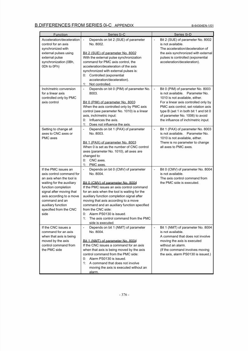
8/16/2019 Manual Operacion para FANUC
http://slidepdf.com/reader/full/manual-operacion-para-fanuc 394/435
B.DIFFERENCES FROM SERIES 0i-C APPENDIX B-64304EN-1/01
- 376 -
Function Series 0i-C Series 0i-D
Acceleration/deceleration
control for an axis
synchronized with
external pulses using
external pulse
synchronization (0Bh,
0Dh to 0Fh)
- Depends on bit 2 (SUE) of parameter
No. 8002.
Bit 2 (SUE) of parameter No. 8002
With the external pulse synchronization
command for PMC axis control, the
acceleration/deceleration of the axis
synchronized with external pulses is:
0: Controlled (exponential
acceleration/deceleration).
1: Not controlled.
- Bit 2 (SUE) of parameter No. 8002
is not available.
The acceleration/deceleration of
the axis synchronized with external
pulses is controlled (exponential
acceleration/deceleration).
Inch/metric conversion
for a linear axis
controlled only by PMC
axis control
- Depends on bit 0 (PIM) of parameter No.
8003.
Bit 0 (PIM) of parameter No. 8003
When the axis controlled only by PMC axis
control (see parameter No. 1010) is a linearaxis, inch/metric input:
0: Influences the axis.
1: Does not influence the axis.
- Bit 0 (PIM) of parameter No. 8003
is not available. Parameter No.
1010 is not available, either.
For a linear axis controlled only by
PMC axis control, set rotation axis
type B (set 1 in both bit 1 and bit 0of parameter No. 1006) to avoid
the influence of inch/metric input.
Setting to change all
axes to CNC axes or
PMC axes
- Depends on bit 1 (PAX) of parameter
No. 8003.
Bit 1 (PAX) of parameter No. 8003
When 0 is set as the number of CNC control
axes (parameter No. 1010), all axes are
changed to:
0: CNC axes.
1: PMC axes.
- Bit 1 (PAX) of parameter No. 8003
is not available. Parameter No.
1010 is not available, either.
There is no parameter to change
all axes to PMC axes.
If the PMC issues an
axis control command for
an axis when the tool is
waiting for the auxiliary
function completion
signal after moving that
axis according to a move
command and an
auxiliary function
specified from the CNC
side
- Depends on bit 0 (CMV) of parameter
No. 8004.
Bit 0 (CMV) of parameter No. 8004
If the PMC issues an axis control command
for an axis when the tool is waiting for the
auxiliary function completion signal after
moving that axis according to a move
command and an auxiliary function specified
from the CNC side:
0: Alarm PS0130 is issued.
1: The axis control command from the PMC
side is executed.
- Bit 0 (CMV) of parameter No. 8004
is not available.
The axis control command from
the PMC side is executed.
If the CNC issues a
command for an axis
when that axis is being
moved by the axis
control command from
the PMC side
- Depends on bit 1 (NMT) of parameter
No. 8004.
Bit 1 (NMT) of parameter No. 8004
If the CNC issues a command for an axis
when that axis is being moved by the axis
control command from the PMC side:
0: Alarm PS0130 is issued.
1: A command that does not involve
moving the axis is executed without an
alarm.
- Bit 1 (NMT) of parameter No. 8004
is not available.
A command that does not involve
moving the axis is executed
without an alarm.
(If the command involves moving
the axis, alarm PS0130 is issued.)
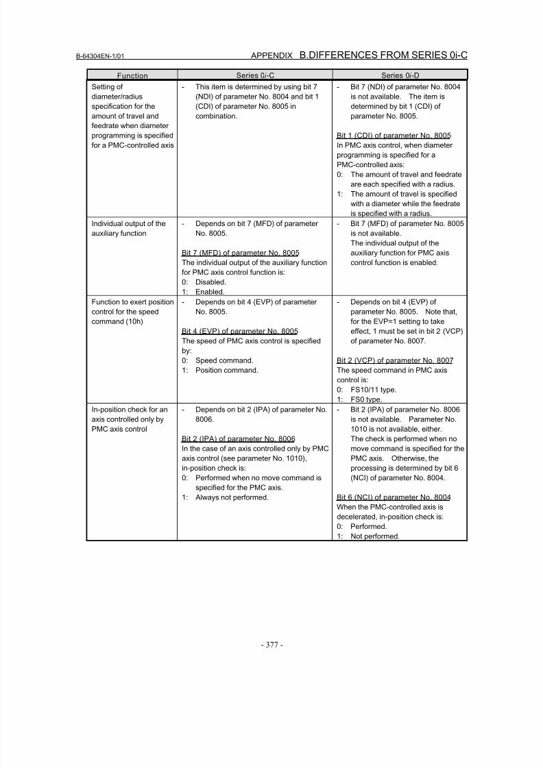
8/16/2019 Manual Operacion para FANUC
http://slidepdf.com/reader/full/manual-operacion-para-fanuc 395/435
B-64304EN-1/01 APPENDIX B.DIFFERENCES FROM SERIES 0i-C
- 377 -
Function Series 0i-C Series 0i-D
Setting of
diameter/radius
specification for the
amount of travel and
feedrate when diameter
programming is specified
for a PMC-controlled axis
- This item is determined by using bit 7
(NDI) of parameter No. 8004 and bit 1
(CDI) of parameter No. 8005 in
combination.
- Bit 7 (NDI) of parameter No. 8004
is not available. The item is
determined by bit 1 (CDI) of
parameter No. 8005.
Bit 1 (CDI) of parameter No. 8005
In PMC axis control, when diameter
programming is specified for a
PMC-controlled axis:
0: The amount of travel and feedrate
are each specified with a radius.
1: The amount of travel is specified
with a diameter while the feedrate
is specified with a radius.
Individual output of the
auxiliary function
- Depends on bit 7 (MFD) of parameter
No. 8005.
Bit 7 (MFD) of parameter No. 8005
The individual output of the auxiliary function
for PMC axis control function is:
0: Disabled.
1: Enabled.
- Bit 7 (MFD) of parameter No. 8005
is not available.
The individual output of theauxiliary function for PMC axis
control function is enabled.
Function to exert position
control for the speed
command (10h)
- Depends on bit 4 (EVP) of parameter
No. 8005.
Bit 4 (EVP) of parameter No. 8005
The speed of PMC axis control is specified
by:
0: Speed command.1: Position command.
- Depends on bit 4 (EVP) of
parameter No. 8005. Note that,
for the EVP=1 setting to take
effect, 1 must be set in bit 2 (VCP)
of parameter No. 8007.
Bit 2 (VCP) of parameter No. 8007The speed command in PMC axis
control is:
0: FS10/11 type.
1: FS0 type.
In-position check for an
axis controlled only by
PMC axis control
- Depends on bit 2 (IPA) of parameter No.
8006.
Bit 2 (IPA) of parameter No. 8006
In the case of an axis controlled only by PMC
axis control (see parameter No. 1010),
in-position check is:
0: Performed when no move command is
specified for the PMC axis.
1: Always not performed.
- Bit 2 (IPA) of parameter No. 8006
is not available. Parameter No.
1010 is not available, either.
The check is performed when no
move command is specified for the
PMC axis. Otherwise, the
processing is determined by bit 6
(NCI) of parameter No. 8004.
Bit 6 (NCI) of parameter No. 8004
When the PMC-controlled axis is
decelerated, in-position check is:
0: Performed.
1: Not performed.
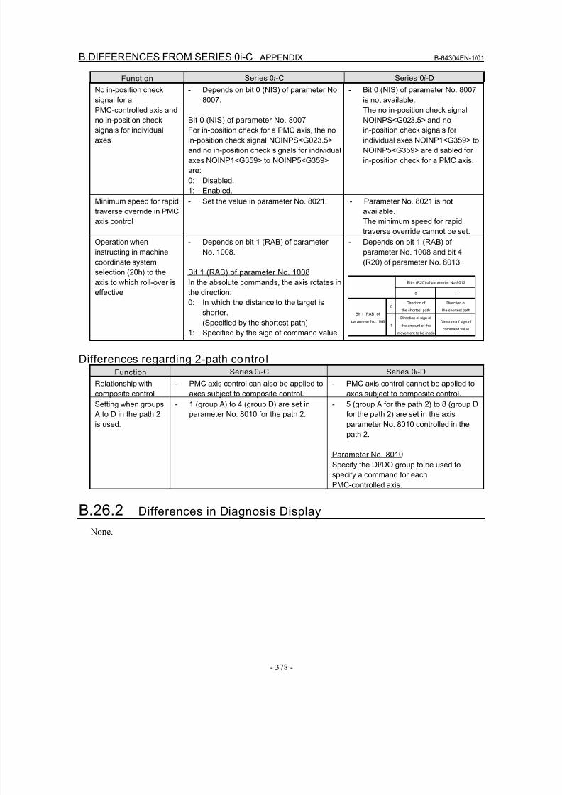
8/16/2019 Manual Operacion para FANUC
http://slidepdf.com/reader/full/manual-operacion-para-fanuc 396/435
B.DIFFERENCES FROM SERIES 0i-C APPENDIX B-64304EN-1/01
- 378 -
Function Series 0i-C Series 0i-D
No in-position check
signal for a
PMC-controlled axis and
no in-position check
signals for individual
axes
- Depends on bit 0 (NIS) of parameter No.
8007.
Bit 0 (NIS) of parameter No. 8007
For in-position check for a PMC axis, the no
in-position check signal NOINPS<G023.5>
and no in-position check signals for individual
axes NOINP1<G359> to NOINP5<G359>
are:
0: Disabled.
1: Enabled.
- Bit 0 (NIS) of parameter No. 8007
is not available.
The no in-position check signal
NOINPS<G023.5> and no
in-position check signals for
individual axes NOINP1<G359> to
NOINP5<G359> are disabled for
in-position check for a PMC axis.
Minimum speed for rapid
traverse override in PMC
axis control
- Set the value in parameter No. 8021. - Parameter No. 8021 is not
available.
The minimum speed for rapid
traverse override cannot be set.
Operation when
instructing in machine
coordinate system
selection (20h) to the
axis to which roll-over is
effective
- Depends on bit 1 (RAB) of parameter
No. 1008.
Bit 1 (RAB) of parameter No. 1008
In the absolute commands, the axis rotates in
the direction:
0: In which the distance to the target is
shorter.
(Specified by the shortest path)
1: Specified by the sign of command value.
- Depends on bit 1 (RAB) of
parameter No. 1008 and bit 4
(R20) of parameter No. 8013.
Bit 4 (R20) of parameter No.8013
0 1
0Direction of
the shortest path
Direction of
the shortest pathBit 1 (RAB) of
parameter No.10081
Direction of sign of
the amount of the
movement to be made
Direction of sign of
command value
Differences regarding 2-path control
Function Series 0i-C Series 0
i-D
Relationship with
composite control
- PMC axis control can also be applied to
axes subject to composite control.
- PMC axis control cannot be applied to
axes subject to composite control.
Setting when groups
A to D in the path 2
is used.
- 1 (group A) to 4 (group D) are set in
parameter No. 8010 for the path 2.
- 5 (group A for the path 2) to 8 (group D
for the path 2) are set in the axis
parameter No. 8010 controlled in the
path 2.
Parameter No. 8010
Specify the DI/DO group to be used to
specify a command for each
PMC-controlled axis.
B.26.2 Differences in Diagnosis Display
None.
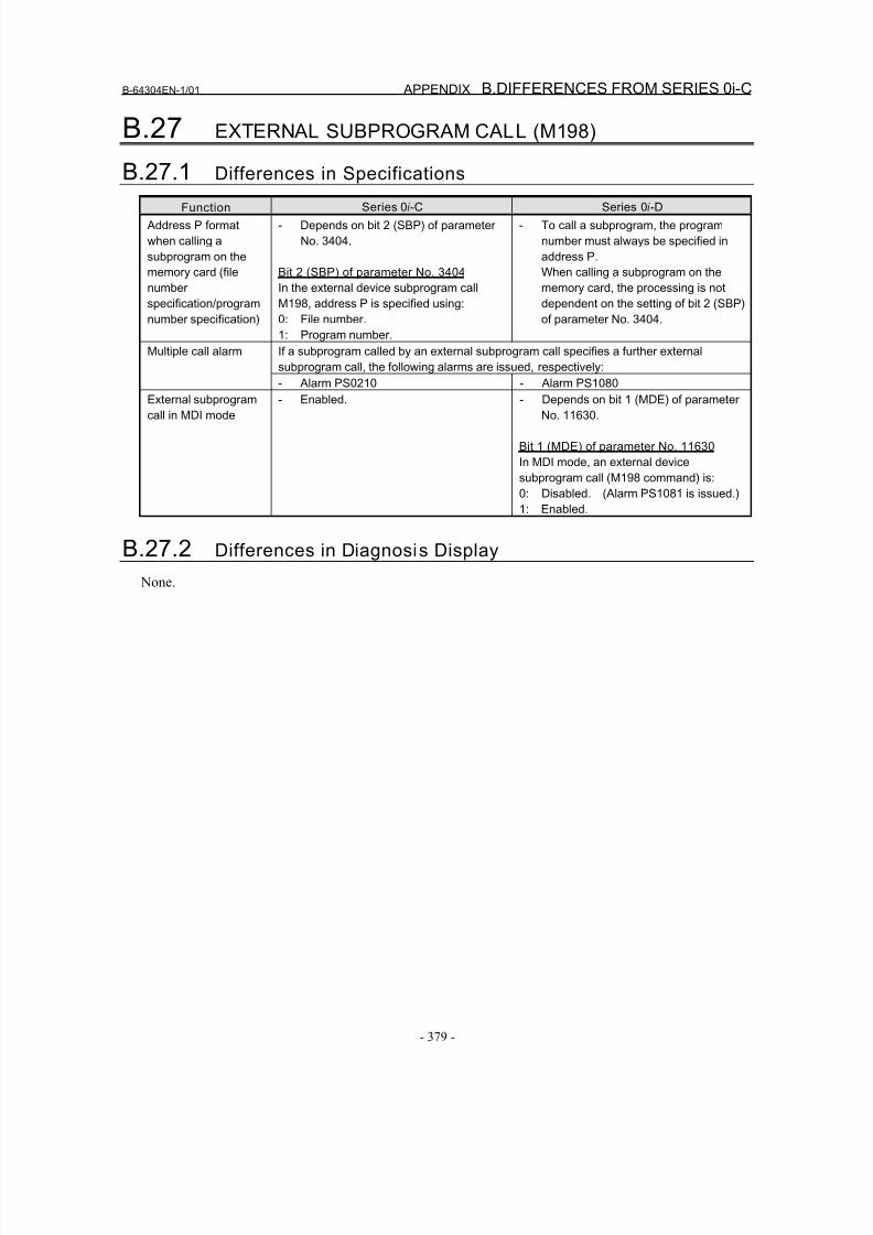
8/16/2019 Manual Operacion para FANUC
http://slidepdf.com/reader/full/manual-operacion-para-fanuc 397/435
B-64304EN-1/01 APPENDIX B.DIFFERENCES FROM SERIES 0i-C
- 379 -
B.27 EXTERNAL SUBPROGRAM CALL (M198)
B.27.1 Differences in Specifications
Function Series 0i-C Series 0i-D
Address P format
when calling a
subprogram on the
memory card (file
number
specification/program
number specification)
- Depends on bit 2 (SBP) of parameter
No. 3404.
Bit 2 (SBP) of parameter No. 3404
In the external device subprogram call
M198, address P is specified using:
0: File number.
1: Program number.
- To call a subprogram, the program
number must always be specified in
address P.
When calling a subprogram on the
memory card, the processing is not
dependent on the setting of bit 2 (SBP)
of parameter No. 3404.
If a subprogram called by an external subprogram call specifies a further external
subprogram call, the following alarms are issued, respectively:
Multiple call alarm
- Alarm PS0210 - Alarm PS1080External subprogram
call in MDI mode
- Enabled. - Depends on bit 1 (MDE) of parameter
No. 11630.
Bit 1 (MDE) of parameter No. 11630
In MDI mode, an external device
subprogram call (M198 command) is:
0: Disabled. (Alarm PS1081 is issued.)
1: Enabled.
B.27.2 Differences in Diagnosis Display
None.
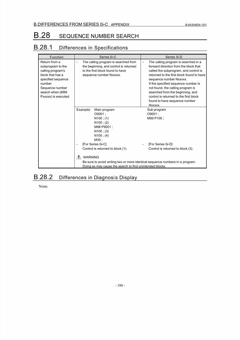
8/16/2019 Manual Operacion para FANUC
http://slidepdf.com/reader/full/manual-operacion-para-fanuc 398/435
B.DIFFERENCES FROM SERIES 0i-C APPENDIX B-64304EN-1/01
- 380 -
B.28 SEQUENCE NUMBER SEARCH
B.28.1 Differences in Specifications
Function Series 0i-C Series 0i-D
- The calling program is searched from
the beginning, and control is returned
to the first block found to have
sequence number Nxxxxx.
- The calling program is searched in a
forward direction from the block that
called the subprogram, and control is
returned to the first block found to have
sequence number Nxxxxx.
If the specified sequence number is
not found, the calling program is
searched from the beginning, and
control is returned to the first block
found to have sequence number
Nxxxxx.Example) Main program
O0001 ;
N100 ; (1)
N100 ; (2)
M98 P9001 ;
N100 ; (3)
N100 ; (4)
M30 ;
Sub program
O9001 ;
M99 P100 ;
- [For Series 0i-C]
Control is returned to block (1).
- [For Series 0i-D]
Control is returned to block (3).
Return from a
subprogram to the
calling program's
block that has a
specified sequence
number
Sequence number
search when (M99
Pxxxxx) is executed
WARNING
Be sure to avoid writing two or more identical sequence numbers in a program.
Doing so may cause the search to find unintended blocks.
B.28.2 Differences in Diagnosis Display
None.
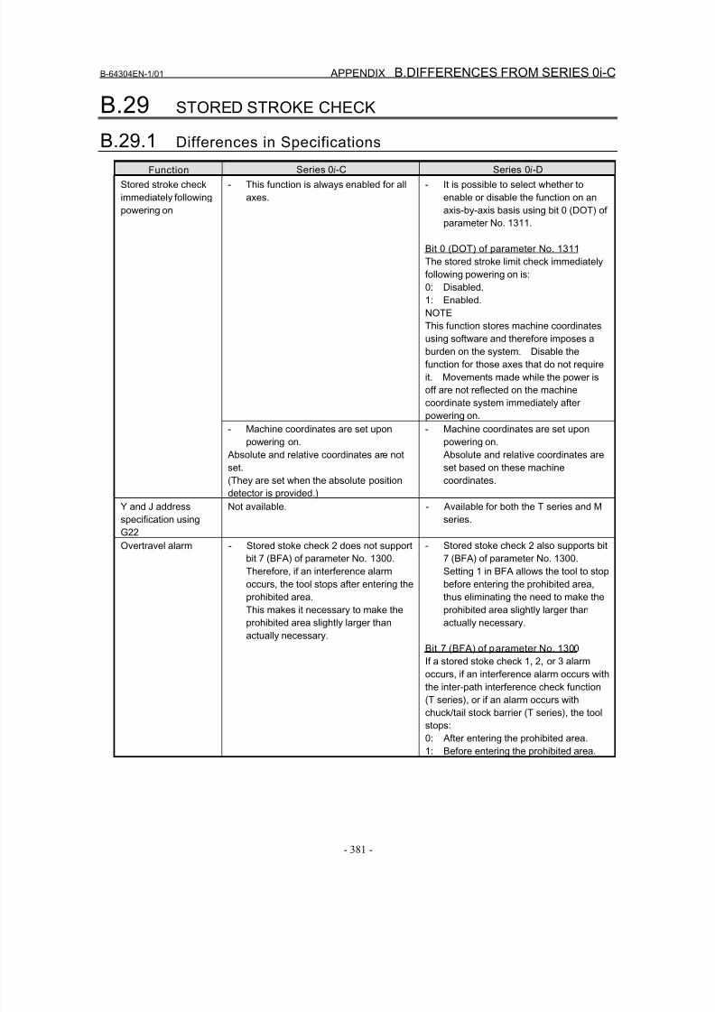
8/16/2019 Manual Operacion para FANUC
http://slidepdf.com/reader/full/manual-operacion-para-fanuc 399/435
B-64304EN-1/01 APPENDIX B.DIFFERENCES FROM SERIES 0i-C
- 381 -
B.29 STORED STROKE CHECK
B.29.1 Differences in Specifications
Function Series 0i-C Series 0i-D
- This function is always enabled for all
axes.
- It is possible to select whether to
enable or disable the function on an
axis-by-axis basis using bit 0 (DOT) of
parameter No. 1311.
Bit 0 (DOT) of parameter No. 1311
The stored stroke limit check immediately
following powering on is:
0: Disabled.
1: Enabled.
NOTEThis function stores machine coordinates
using software and therefore imposes a
burden on the system. Disable the
function for those axes that do not require
it. Movements made while the power is
off are not reflected on the machine
coordinate system immediately after
powering on.
Stored stroke check
immediately following
powering on
- Machine coordinates are set upon
powering on.
Absolute and relative coordinates are not
set.
(They are set when the absolute position
detector is provided.)
- Machine coordinates are set upon
powering on.
Absolute and relative coordinates are
set based on these machine
coordinates.
Y and J address
specification using
G22
Not available. - Available for both the T series and M
series.
Overtravel alarm - Stored stoke check 2 does not support
bit 7 (BFA) of parameter No. 1300.
Therefore, if an interference alarm
occurs, the tool stops after entering the
prohibited area.
This makes it necessary to make the
prohibited area slightly larger than
actually necessary.
- Stored stoke check 2 also supports bit
7 (BFA) of parameter No. 1300.
Setting 1 in BFA allows the tool to stop
before entering the prohibited area,
thus eliminating the need to make the
prohibited area slightly larger than
actually necessary.
Bit 7 (BFA) of parameter No. 1300
If a stored stoke check 1, 2, or 3 alarm
occurs, if an interference alarm occurs with
the inter-path interference check function
(T series), or if an alarm occurs with
chuck/tail stock barrier (T series), the tool
stops:
0: After entering the prohibited area.
1: Before entering the prohibited area.
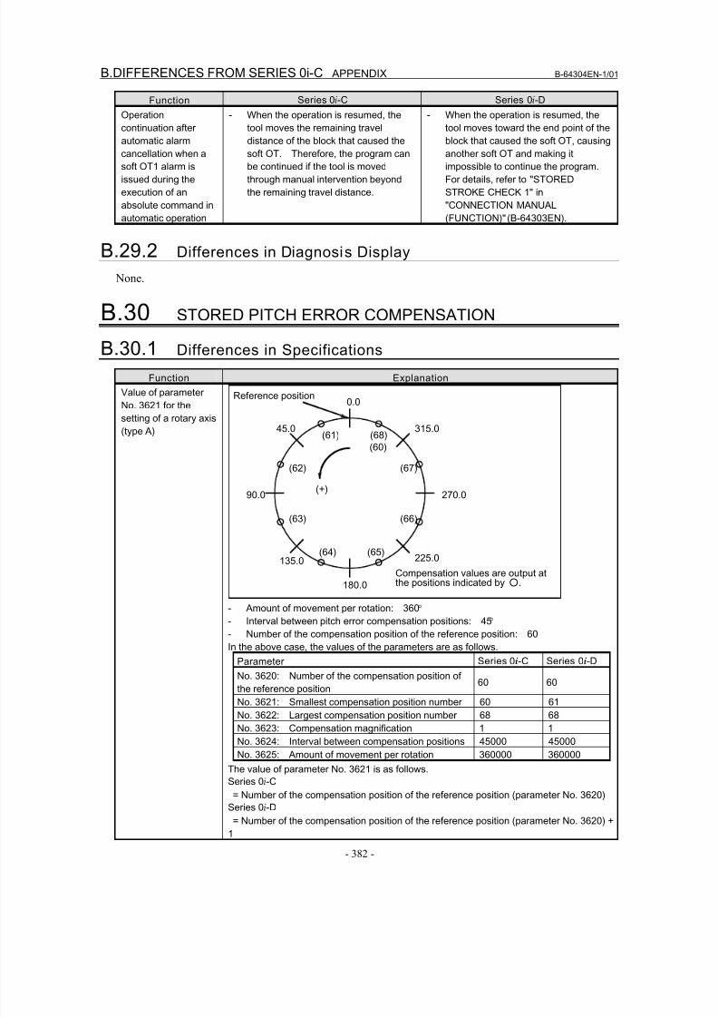
8/16/2019 Manual Operacion para FANUC
http://slidepdf.com/reader/full/manual-operacion-para-fanuc 400/435
B.DIFFERENCES FROM SERIES 0i-C APPENDIX B-64304EN-1/01
- 382 -
Function Series 0i-C Series 0i-D
Operation
continuation after
automatic alarm
cancellation when a
soft OT1 alarm is
issued during the
execution of an
absolute command in
automatic operation
- When the operation is resumed, the
tool moves the remaining travel
distance of the block that caused the
soft OT. Therefore, the program can
be continued if the tool is moved
through manual intervention beyond
the remaining travel distance.
- When the operation is resumed, the
tool moves toward the end point of the
block that caused the soft OT, causing
another soft OT and making it
impossible to continue the program.
For details, refer to "STORED
STROKE CHECK 1" in
"CONNECTION MANUAL
(FUNCTION)" (B-64303EN).
B.29.2 Differences in Diagnosis Display
None.
B.30 STORED PITCH ERROR COMPENSATION
B.30.1 Differences in Specifications
Function Explanation
Value of parameter
No. 3621 for the
setting of a rotary axis
(type A)
0.0
45.0
90.0
135.0
180.0
225.0
270.0
315.0(68)
(60)
(67)
(66)
(65)(64)
(63)
(62)
(61)
(+)
Reference position
Compensation values are output atthe positions indicated by ○.
- Amount of movement per rotation: 360°
- Interval between pitch error compensation positions: 45°
- Number of the compensation position of the reference position: 60In the above case, the values of the parameters are as follows.
Parameter Series 0i-C Series 0i-D
No. 3620: Number of the compensation position of
the reference position60 60
No. 3621: Smallest compensation position number 60 61
No. 3622: Largest compensation position number 68 68
No. 3623: Compensation magnification 1 1
No. 3624: Interval between compensation positions 45000 45000
No. 3625: Amount of movement per rotation 360000 360000
The value of parameter No. 3621 is as follows.
Series 0i-C
= Number of the compensation position of the reference position (parameter No. 3620)Series 0i-D
= Number of the compensation position of the reference position (parameter No. 3620) +
1
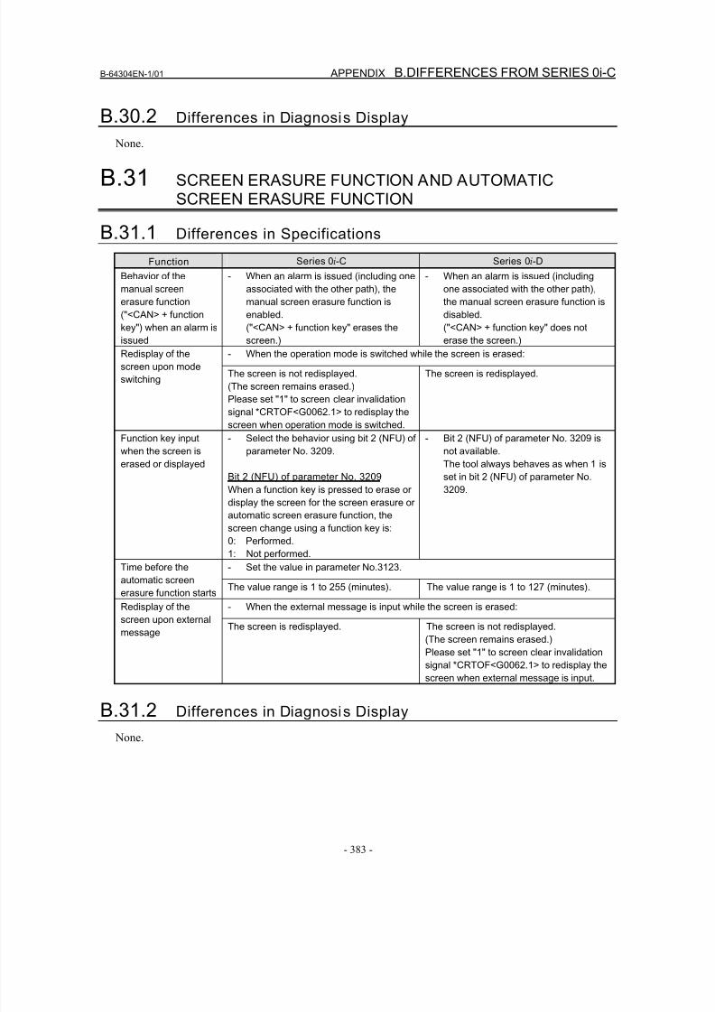
8/16/2019 Manual Operacion para FANUC
http://slidepdf.com/reader/full/manual-operacion-para-fanuc 401/435
B-64304EN-1/01 APPENDIX B.DIFFERENCES FROM SERIES 0i-C
- 383 -
B.30.2 Differences in Diagnosis Display
None.
B.31 SCREEN ERASURE FUNCTION AND AUTOMATICSCREEN ERASURE FUNCTION
B.31.1 Differences in Specifications
Function Series 0i-C Series 0i-D
Behavior of the
manual screen
erasure function
("<CAN> + functionkey") when an alarm is
issued
- When an alarm is issued (including one
associated with the other path), the
manual screen erasure function is
enabled.("<CAN> + function key" erases the
screen.)
- When an alarm is issued (including
one associated with the other path),
the manual screen erasure function is
disabled.("<CAN> + function key" does not
erase the screen.)
- When the operation mode is switched while the screen is erased:Redisplay of the
screen upon mode
switchingThe screen is not redisplayed.
(The screen remains erased.)
Please set "1" to screen clear invalidation
signal *CRTOF<G0062.1> to redisplay the
screen when operation mode is switched.
The screen is redisplayed.
Function key input
when the screen is
erased or displayed
- Select the behavior using bit 2 (NFU) of
parameter No. 3209.
Bit 2 (NFU) of parameter No. 3209When a function key is pressed to erase or
display the screen for the screen erasure or
automatic screen erasure function, the
screen change using a function key is:
0: Performed.
1: Not performed.
- Bit 2 (NFU) of parameter No. 3209 is
not available.
The tool always behaves as when 1 is
set in bit 2 (NFU) of parameter No.3209.
- Set the value in parameter No.3123.Time before the
automatic screen
erasure function startsThe value range is 1 to 255 (minutes). The value range is 1 to 127 (minutes).
- When the external message is input while the screen is erased:Redisplay of the
screen upon external
message
The screen is redisplayed. The screen is not redisplayed.
(The screen remains erased.)
Please set "1" to screen clear invalidation
signal *CRTOF<G0062.1> to redisplay the
screen when external message is input.
B.31.2 Differences in Diagnosis Display
None.
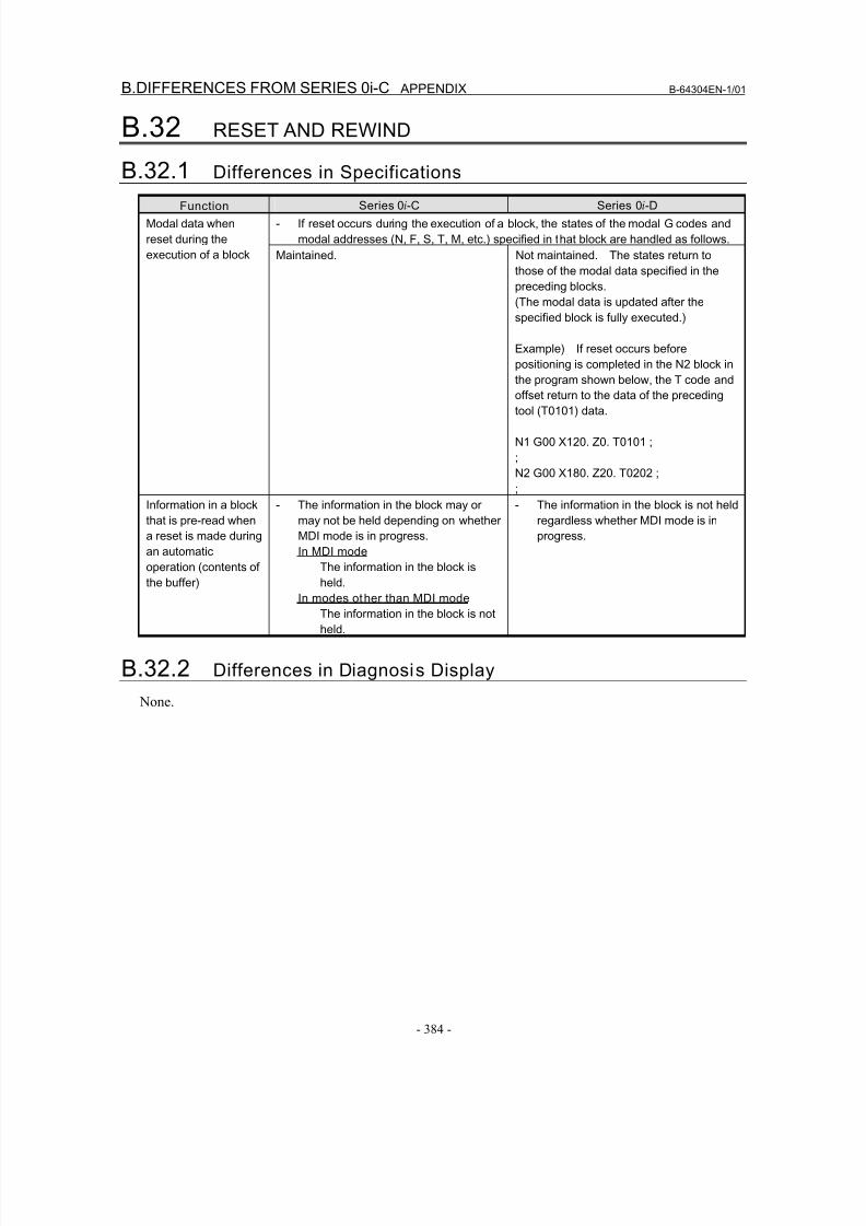
8/16/2019 Manual Operacion para FANUC
http://slidepdf.com/reader/full/manual-operacion-para-fanuc 402/435
B.DIFFERENCES FROM SERIES 0i-C APPENDIX B-64304EN-1/01
- 384 -
B.32 RESET AND REWIND
B.32.1 Differences in Specifications
Function Series 0i-C Series 0i-D
- If reset occurs during the execution of a block, the states of the modal G codes and
modal addresses (N, F, S, T, M, etc.) specified in that block are handled as follows.
Modal data when
reset during the
execution of a block Maintained. Not maintained. The states return to
those of the modal data specified in the
preceding blocks.
(The modal data is updated after the
specified block is fully executed.)
Example) If reset occurs before
positioning is completed in the N2 block in
the program shown below, the T code andoffset return to the data of the preceding
tool (T0101) data.
N1 G00 X120. Z0. T0101 ;
;
N2 G00 X180. Z20. T0202 ;
;
Information in a block
that is pre-read when
a reset is made during
an automatic
operation (contents of
the buffer)
- The information in the block may or
may not be held depending on whether
MDI mode is in progress.
In MDI mode
The information in the block is
held.
In modes other than MDI mode
The information in the block is not
held.
- The information in the block is not held
regardless whether MDI mode is in
progress.
B.32.2 Differences in Diagnosis Display
None.
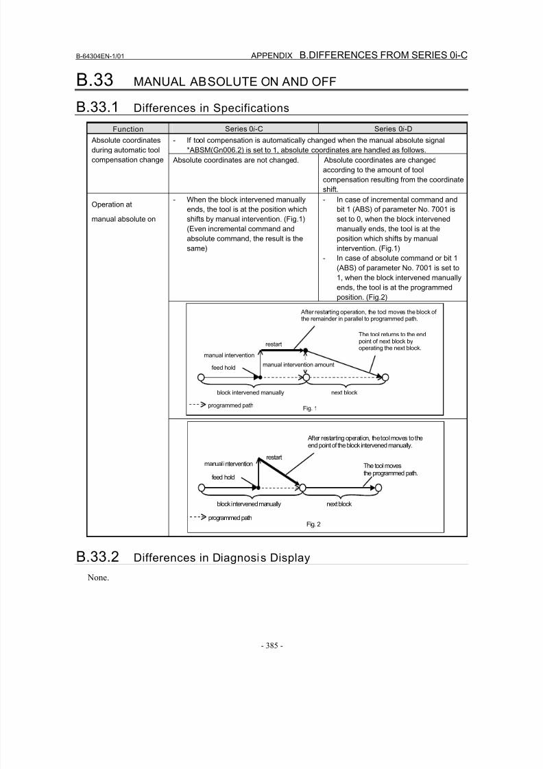
8/16/2019 Manual Operacion para FANUC
http://slidepdf.com/reader/full/manual-operacion-para-fanuc 403/435
B-64304EN-1/01 APPENDIX B.DIFFERENCES FROM SERIES 0i-C
- 385 -
B.33 MANUAL ABSOLUTE ON AND OFF
B.33.1 Differences in Specifications
Function Series 0i-C Series 0i-D
- If tool compensation is automatically changed when the manual absolute signal
*ABSM(Gn006.2) is set to 1, absolute coordinates are handled as follows.
Absolute coordinates
during automatic tool
compensation change Absolute coordinates are not changed. Absolute coordinates are changed
according to the amount of tool
compensation resulting from the coordinate
shift.
- When the block intervened manually
ends, the tool is at the position which
shifts by manual intervention. (Fig.1)
(Even incremental command and
absolute command, the result is thesame)
- In case of incremental command and
bit 1 (ABS) of parameter No. 7001 is
set to 0, when the block intervened
manually ends, the tool is at the
position which shifts by manualintervention. (Fig.1)
- In case of absolute command or bit 1
(ABS) of parameter No. 7001 is set to
1, when the block intervened manually
ends, the tool is at the programmed
position. (Fig.2)
Operation at
manual absolute on
B.33.2 Differences in Diagnosis Display
None.
next block
programmed path
block intervened manually
feed hold
manual intervention
restart
manual intervention amount
After restarting operation, the tool moves the block ofthe remainder in parallel to programmed path.
The tool returns to the endpoint of next block byoperating the next block.
Fig. 1
next block
programmed path
block intervened manually
feed hold
manual interventionrestart
After restarting operation, the tool moves to theend point of the block intervened manually.
The tool movesthe programmed path.
Fig. 2
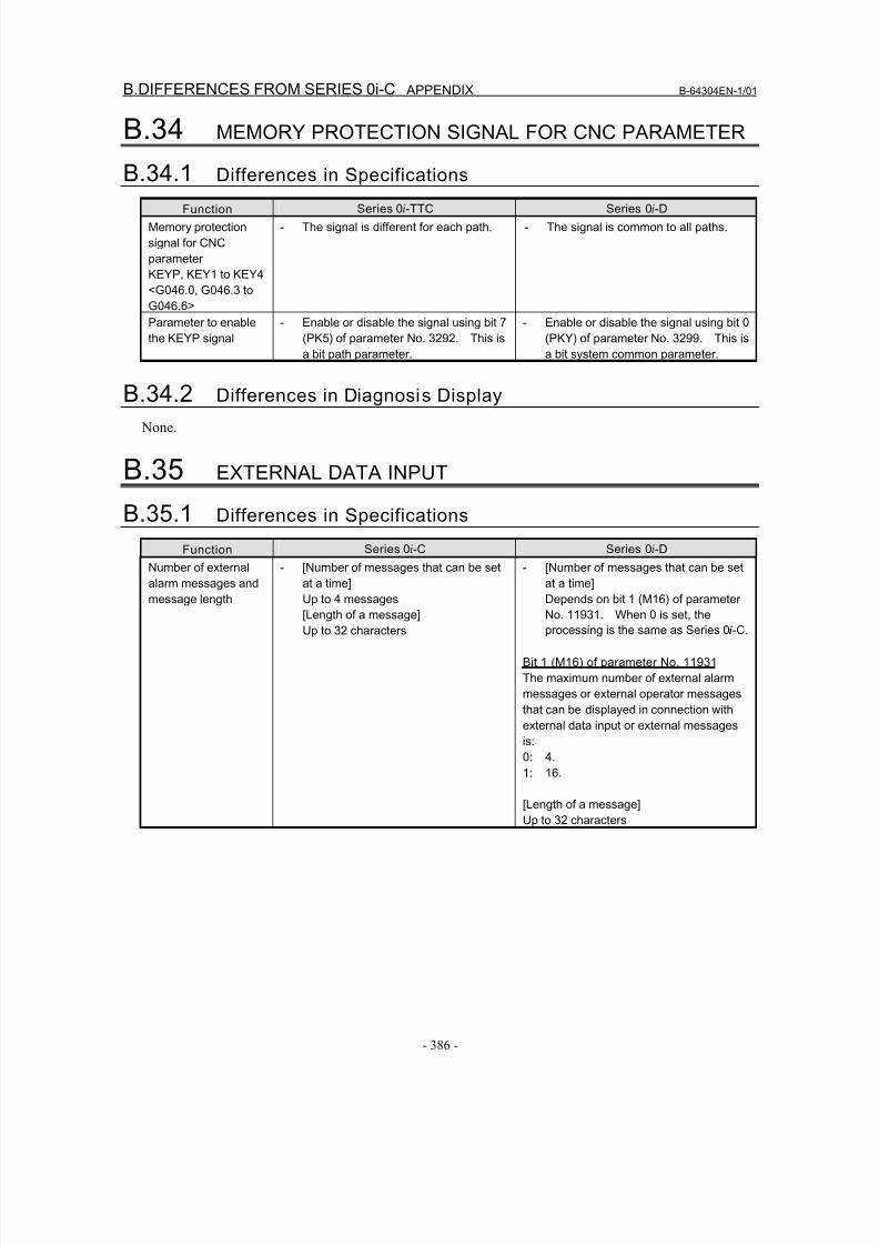
8/16/2019 Manual Operacion para FANUC
http://slidepdf.com/reader/full/manual-operacion-para-fanuc 404/435
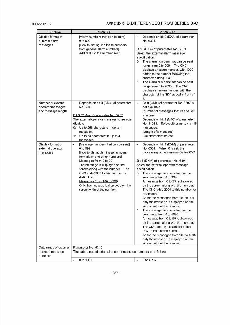
8/16/2019 Manual Operacion para FANUC
http://slidepdf.com/reader/full/manual-operacion-para-fanuc 405/435
B-64304EN-1/01 APPENDIX B.DIFFERENCES FROM SERIES 0i-C
- 387 -
Function Series 0i-C Series 0i-D
Display format of
external alarm
messages
- [Alarm numbers that can be sent]
0 to 999
[How to distinguish these numbers
from general alarm numbers]
Add 1000 to the number sent
- Depends on bit 0 (EXA) of parameter
No. 6301.
Bit 0 (EXA) of parameter No. 6301
Select the external alarm message
specification.
0: The alarm numbers that can be sent
range from 0 to 999. The CNC
displays an alarm number, with 1000
added to the number following the
character string "EX".
1: The alarm numbers that can be sent
range from 0 to 4095. The CNC
displays an alarm number, with the
character string "EX" added in front of
it.
Number of externaloperator messages
and message length
- Depends on bit 0 (OM4) of parameterNo. 3207.
Bit 0 (OM4) of parameter No. 3207
The external operator message screen can
display:
0: Up to 256 characters in up to 1
message.
1: Up to 64 characters in up to 4
messages.
- Bit 0 (OM4) of parameter No. 3207 isnot available.
[Number of messages that can be set
at a time]
Depends on bit 1 (M16) of parameter
No. 11931. Select either up to 4 or 16
messages.
[Length of a message]
256 characters or less
Display format of
external operator
messages
- [Message numbers that can be sent]
0 to 999
[How to distinguish these numbersfrom alarm and other numbers]
Messages from 0 to 99
The message is displayed on the
screen along with the number. The
CNC adds 2000 to this number for
distinction.
Messages from 100 to 999
Only the message is displayed on the
screen without the number.
- Depends on bit 1 (EXM) of parameter
No. 6301. When 0 is set, the
processing is the same as Series 0i-C.
Bit 1 (EXM) of parameter No. 6301
Select the external operator message
specification.
0: The message numbers that can be
sent range from 0 to 999.
A message from 0 to 99 is displayed
on the screen along with the number.
The CNC adds 2000 to this number for
distinction.
As for the messages from 100 to 999,
only the message is displayed on the
screen without the number.
1: The message numbers that can be
sent range from 0 to 4095.
A message from 0 to 99 is displayed
on the screen along with the number.
The CNC adds the character string
"EX" in front of the number.
As for the messages from 100 to 4095,
only the message is displayed on the
screen without the number.
Parameter No. 6310
The data range of external operator message numbers is as follows.
Data range of external
operator message
numbers- 0 to 1000 - 0 to 4096
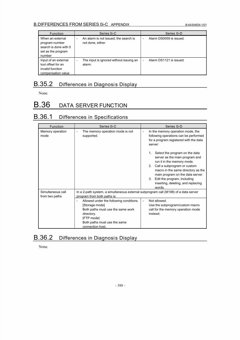
8/16/2019 Manual Operacion para FANUC
http://slidepdf.com/reader/full/manual-operacion-para-fanuc 406/435
B.DIFFERENCES FROM SERIES 0i-C APPENDIX B-64304EN-1/01
- 388 -
Function Series 0i-C Series 0i-D
When an external
program number
search is done with 0
set as the program
number
- An alarm is not issued; the search is
not done, either.
- Alarm DS0059 is issued.
Input of an external
tool offset for an
invalid function
compensation value
- The input is ignored without issuing an
alarm.
- Alarm DS1121 is issued.
B.35.2 Differences in Diagnosis Display
None.
B.36 DATA SERVER FUNCTION
B.36.1 Differences in Specifications
Function Series 0i-C Series 0i-D
Memory operation
mode
- The memory operation mode is not
supported.
- In the memory operation mode, the
following operations can be performed
for a program registered with the data
server:
1. Select the program on the data
server as the main program and
run it in the memory mode.
2. Call a subprogram or custom
macro in the same directory as the
main program on the data server.
3. Edit the program, including
inserting, deleting, and replacing
words.
In a 2-path system, a simultaneous external subprogram call (M198) of a data server
program from both paths is:
Simultaneous call
from two paths
- Allowed under the following conditions.
[Storage mode]
Both paths must use the same work
directory.[FTP mode]
Both paths must use the same
connection host.
- Not allowed.
Use the subprogram/custom macro
call for the memory operation mode
instead.
B.36.2 Differences in Diagnosis Display
None.
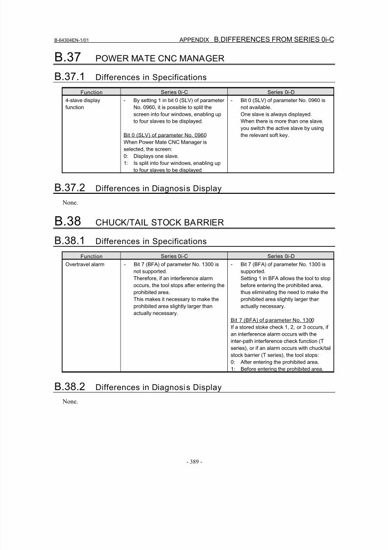
8/16/2019 Manual Operacion para FANUC
http://slidepdf.com/reader/full/manual-operacion-para-fanuc 407/435
B-64304EN-1/01 APPENDIX B.DIFFERENCES FROM SERIES 0i-C
- 389 -
B.37 POWER MATE CNC MANAGER
B.37.1 Differences in Specifications
Function Series 0i-C Series 0i-D
4-slave display
function
- By setting 1 in bit 0 (SLV) of parameter
No. 0960, it is possible to split the
screen into four windows, enabling up
to four slaves to be displayed.
Bit 0 (SLV) of parameter No. 0960
When Power Mate CNC Manager is
selected, the screen:
0: Displays one slave.
1: Is split into four windows, enabling up
to four slaves to be displayed.
- Bit 0 (SLV) of parameter No. 0960 is
not available.
One slave is always displayed.
When there is more than one slave,
you switch the active slave by using
the relevant soft key.
B.37.2 Differences in Diagnosis Display
None.
B.38 CHUCK/TAIL STOCK BARRIER
B.38.1 Differences in Specifications
FunctionSeries 0i-C Series 0i-D
Overtravel alarm - Bit 7 (BFA) of parameter No. 1300 is
not supported.
Therefore, if an interference alarm
occurs, the tool stops after entering the
prohibited area.
This makes it necessary to make the
prohibited area slightly larger than
actually necessary.
- Bit 7 (BFA) of parameter No. 1300 is
supported.
Setting 1 in BFA allows the tool to stop
before entering the prohibited area,
thus eliminating the need to make the
prohibited area slightly larger than
actually necessary.
Bit 7 (BFA) of parameter No. 1300
If a stored stoke check 1, 2, or 3 occurs, if
an interference alarm occurs with the
inter-path interference check function (T
series), or if an alarm occurs with chuck/tail
stock barrier (T series), the tool stops:
0: After entering the prohibited area.
1: Before entering the prohibited area.
B.38.2 Differences in Diagnosis Display
None.
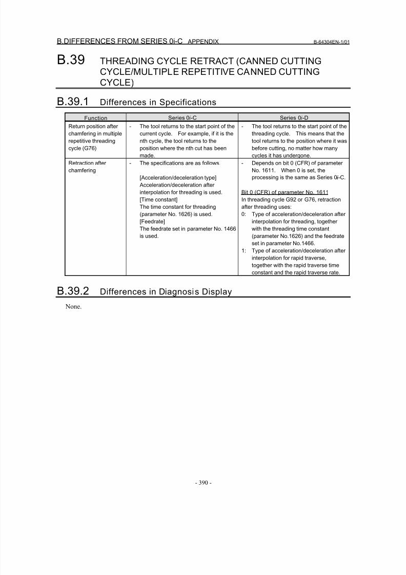
8/16/2019 Manual Operacion para FANUC
http://slidepdf.com/reader/full/manual-operacion-para-fanuc 408/435
B.DIFFERENCES FROM SERIES 0i-C APPENDIX B-64304EN-1/01
- 390 -
B.39 THREADING CYCLE RETRACT (CANNED CUTTINGCYCLE/MULTIPLE REPETITIVE CANNED CUTTING
CYCLE)
B.39.1 Differences in Specifications
Function Series 0i-C Series 0i-D
Return position after
chamfering in multiple
repetitive threading
cycle (G76)
- The tool returns to the start point of the
current cycle. For example, if it is the
nth cycle, the tool returns to the
position where the nth cut has been
made.
- The tool returns to the start point of the
threading cycle. This means that the
tool returns to the position where it was
before cutting, no matter how many
cycles it has undergone.
Retraction after
chamfering
- The specifications are as follows.
[Acceleration/deceleration type] Acceleration/deceleration after
interpolation for threading is used.
[Time constant]
The time constant for threading
(parameter No. 1626) is used.
[Feedrate]
The feedrate set in parameter No. 1466
is used.
- Depends on bit 0 (CFR) of parameter
No. 1611. When 0 is set, the
processing is the same as Series 0i-C.
Bit 0 (CFR) of parameter No. 1611
In threading cycle G92 or G76, retraction
after threading uses:
0: Type of acceleration/deceleration after
interpolation for threading, together
with the threading time constant
(parameter No.1626) and the feedrate
set in parameter No.1466.
1: Type of acceleration/deceleration after
interpolation for rapid traverse,
together with the rapid traverse time
constant and the rapid traverse rate.
B.39.2 Differences in Diagnosis Display
None.
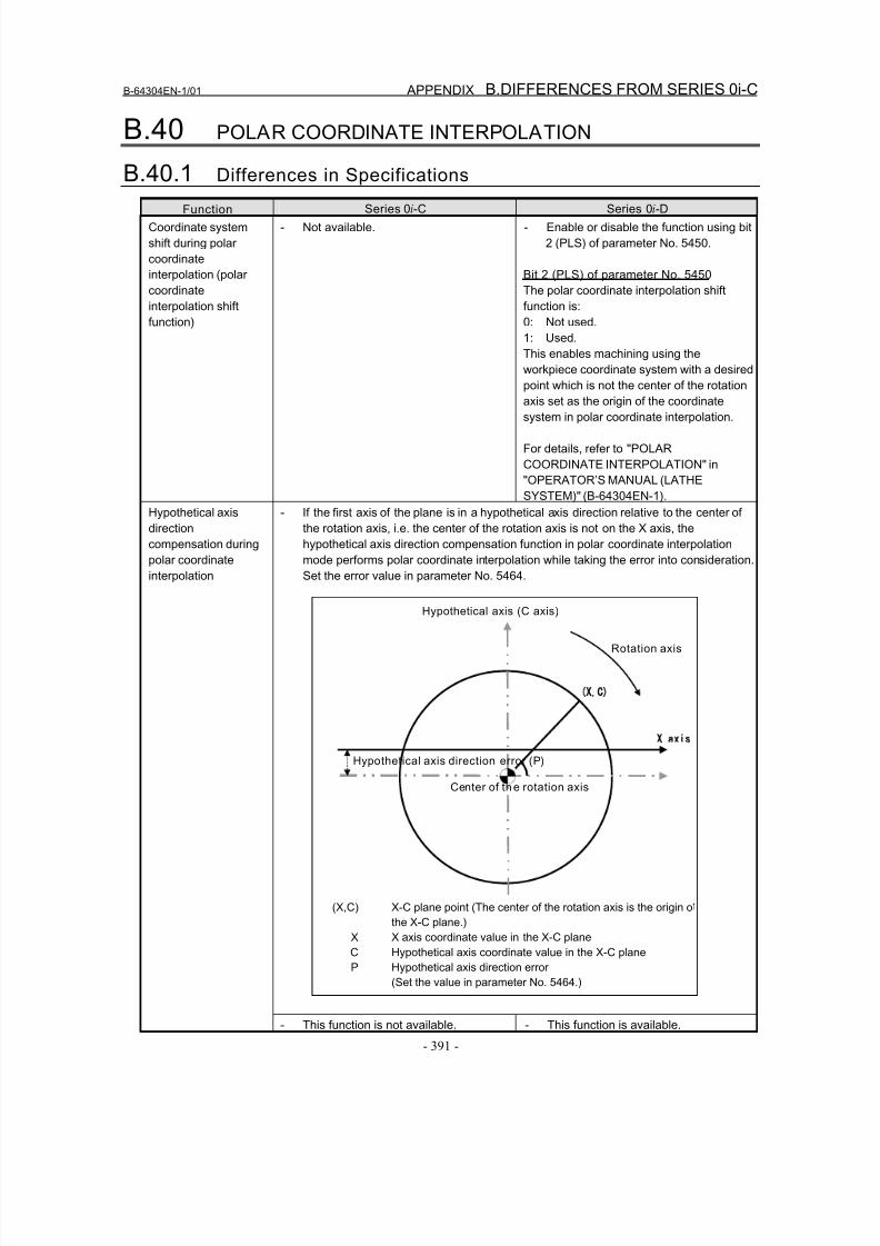
8/16/2019 Manual Operacion para FANUC
http://slidepdf.com/reader/full/manual-operacion-para-fanuc 409/435
B-64304EN-1/01 APPENDIX B.DIFFERENCES FROM SERIES 0i-C
- 391 -
B.40 POLAR COORDINATE INTERPOLATION
B.40.1 Differences in Specifications
Function Series 0i-C Series 0i-D
Coordinate system
shift during polar
coordinate
interpolation (polar
coordinate
interpolation shift
function)
- Not available. - Enable or disable the function using bit
2 (PLS) of parameter No. 5450.
Bit 2 (PLS) of parameter No. 5450
The polar coordinate interpolation shift
function is:
0: Not used.
1: Used.
This enables machining using the
workpiece coordinate system with a desired
point which is not the center of the rotationaxis set as the origin of the coordinate
system in polar coordinate interpolation.
For details, refer to "POLAR
COORDINATE INTERPOLATION" in
"OPERATOR’S MANUAL (LATHE
SYSTEM)" (B-64304EN-1).
- If the first axis of the plane is in a hypothetical axis direction relative to the center of
the rotation axis, i.e. the center of the rotation axis is not on the X axis, the
hypothetical axis direction compensation function in polar coordinate interpolation
mode performs polar coordinate interpolation while taking the error into consideration.
Set the error value in parameter No. 5464.
X,C)
Hypothetical axis (C axis)
Hypothetical axis direction error (P)
Center of the rotation axis
X axis
Rotation axis
(X,C) X-C plane point (The center of the rotation axis is the origin o
the X-C plane.)
X X axis coordinate value in the X-C plane
C Hypothetical axis coordinate value in the X-C plane
P Hypothetical axis direction error
(Set the value in parameter No. 5464.)
Hypothetical axis
direction
compensation during
polar coordinate
interpolation
- This function is not available. - This function is available.
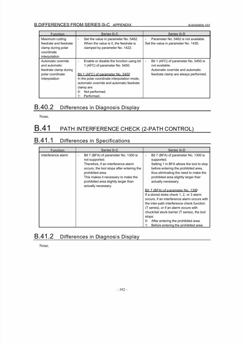
8/16/2019 Manual Operacion para FANUC
http://slidepdf.com/reader/full/manual-operacion-para-fanuc 410/435
B.DIFFERENCES FROM SERIES 0i-C APPENDIX B-64304EN-1/01
- 392 -
Function Series 0i-C Series 0i-D
Maximum cutting
feedrate and feedrate
clamp during polar
coordinate
interpolation
- Set the value in parameter No. 5462.
When the value is 0, the feedrate is
clamped by parameter No. 1422.
- Parameter No. 5462 is not available.
Set the value in parameter No. 1430.
Automatic override
and automatic
feedrate clamp during
polar coordinate
interpolation
- Enable or disable the function using bit
1 (AFC) of parameter No. 5450.
Bit 1 (AFC) of parameter No. 5450
In the polar coordinate interpolation mode,
automatic override and automatic feedrate
clamp are:
0: Not performed.
1: Performed.
- Bit 1 (AFC) of parameter No. 5450 is
not available.
Automatic override and automatic
feedrate clamp are always performed.
B.40.2 Differences in Diagnosis Display None.
B.41 PATH INTERFERENCE CHECK (2-PATH CONTROL)
B.41.1 Differences in Specifications
Function Series 0i-C Series 0i-D
Interference alarm - Bit 7 (BFA) of parameter No. 1300 is
not supported.
Therefore, if an interference alarm
occurs, the tool stops after entering the
prohibited area.
This makes it necessary to make the
prohibited area slightly larger than
actually necessary.
- Bit 7 (BFA) of parameter No. 1300 is
supported.
Setting 1 in BFA allows the tool to stop
before entering the prohibited area,
thus eliminating the need to make the
prohibited area slightly larger than
actually necessary.
Bit 7 (BFA) of parameter No. 1300
If a stored stoke check 1, 2, or 3 alarm
occurs, if an interference alarm occurs with
the inter-path interference check function
(T series), or if an alarm occurs with
chuck/tail stock barrier (T series), the tool
stops:0: After entering the prohibited area.
1: Before entering the prohibited area.
B.41.2 Differences in Diagnosis Display
None.
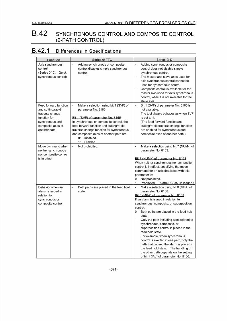
8/16/2019 Manual Operacion para FANUC
http://slidepdf.com/reader/full/manual-operacion-para-fanuc 411/435
B-64304EN-1/01 APPENDIX B.DIFFERENCES FROM SERIES 0i-C
- 393 -
B.42 SYNCHRONOUS CONTROL AND COMPOSITE CONTROL(2-PATH CONTROL)
B.42.1 Differences in Specifications
Function Series 0i-TTC Series 0i-D
Axis synchronous
control
(Series 0i-C: Quick
synchronous control)
- Adding synchronous or composite
control disables simple synchronous
control.
- Adding synchronous or composite
control does not disable simple
synchronous control.
- The master and slave axes used for
axis synchronous control cannot be
used for synchronous control.
- Composite control is available for the
master axis used for axis synchronous
control, while it is not available for the
slave axis.Feed forward function
and cutting/rapid
traverse change
function for
synchronous and
composite axes of
another path
- Make a selection using bit 1 (SVF) of
parameter No. 8165.
Bit 1 (SVF) of parameter No. 8165
In synchronous or composite control, the
feed forward function and cutting/rapid
traverse change function for synchronous
and composite axes of another path are:
0: Disabled.
1: Enabled.
- Bit 1 (SVF) of parameter No. 8165 is
not available.
The tool always behaves as when SVF
is set to 1.
(The feed forward function and
cutting/rapid traverse change function
are enabled for synchronous and
composite axes of another path.)
Move command when
neither synchronousnor composite control
is in effect
- Not prohibited. - Make a selection using bit 7 (NUMx) of
parameter No. 8163.
Bit 7 (NUMx) of parameter No. 8163
When neither synchronous nor composite
control is in effect, specifying the move
command for an axis that is set with this
parameter is:
0: Not prohibited.
1: Prohibited. (Alarm PS0353 is issued.)
Behavior when an
alarm is issued in
relation to
synchronous or
composite control
- Both paths are placed in the feed hold
state.
- Make a selection using bit 0 (MPA) of
parameter No. 8168.
Bit 0 (MPA) of parameter No. 8168
If an alarm is issued in relation to
synchronous, composite, or superposition
control:
0: Both paths are placed in the feed hold
state.
1: Only the path including axes related to
synchronous, composite, or
superposition control is placed in the
feed hold state.
For example, when synchronous
control is exerted in one path, only the
path that caused the alarm is placed in
the feed hold state. The handling of
the other path depends on the settingof bit 1 (IAL) of parameter No. 8100.
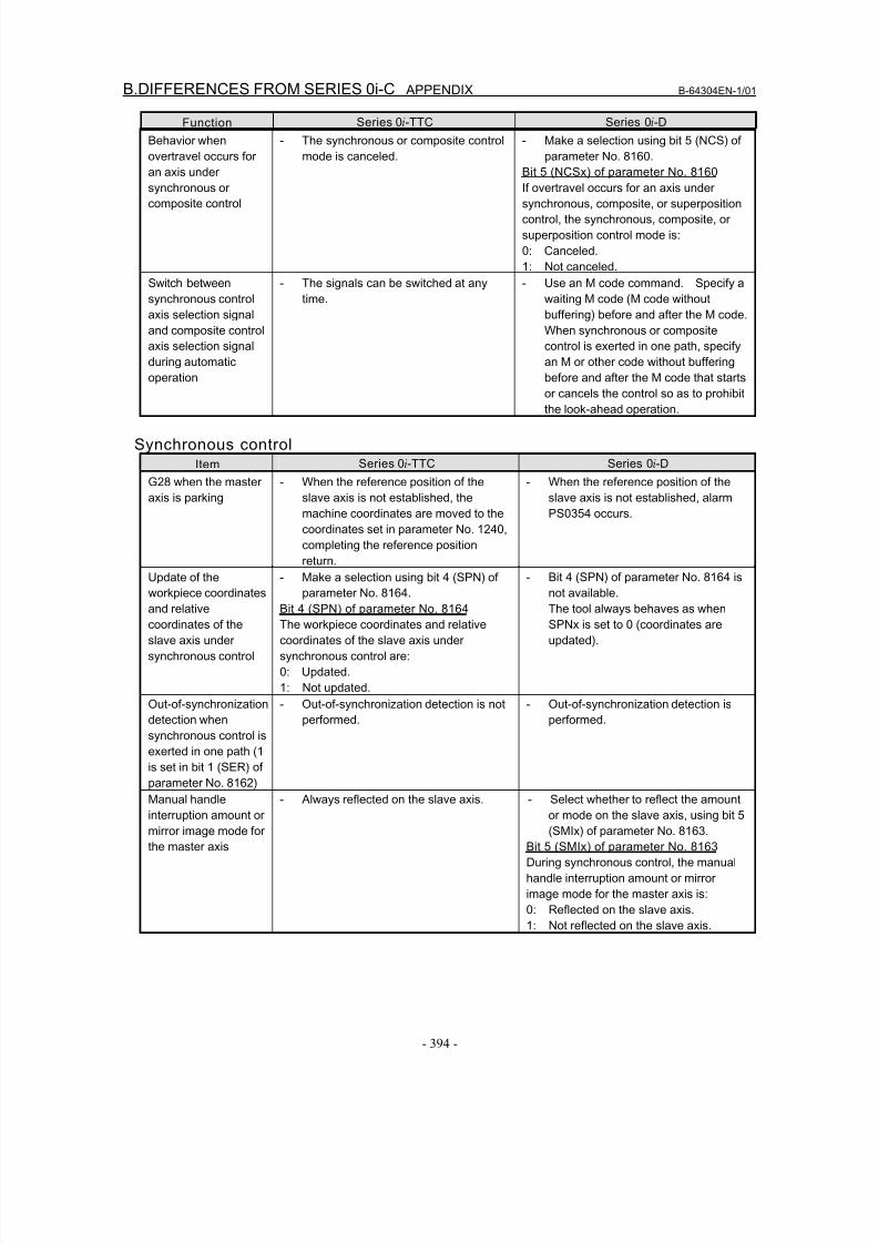
8/16/2019 Manual Operacion para FANUC
http://slidepdf.com/reader/full/manual-operacion-para-fanuc 412/435
B.DIFFERENCES FROM SERIES 0i-C APPENDIX B-64304EN-1/01
- 394 -
Function Series 0i-TTC Series 0i-D
Behavior when
overtravel occurs for
an axis under
synchronous or
composite control
- The synchronous or composite control
mode is canceled.
- Make a selection using bit 5 (NCS) of
parameter No. 8160.
Bit 5 (NCSx) of parameter No. 8160
If overtravel occurs for an axis under
synchronous, composite, or superposition
control, the synchronous, composite, or
superposition control mode is:
0: Canceled.
1: Not canceled.
Switch between
synchronous control
axis selection signal
and composite control
axis selection signal
during automatic
operation
- The signals can be switched at any
time.
- Use an M code command. Specify a
waiting M code (M code without
buffering) before and after the M code.
When synchronous or composite
control is exerted in one path, specify
an M or other code without buffering
before and after the M code that starts
or cancels the control so as to prohibitthe look-ahead operation.
Synchronous controlItem Series 0i-TTC Series 0i-D
G28 when the master
axis is parking
- When the reference position of the
slave axis is not established, the
machine coordinates are moved to the
coordinates set in parameter No. 1240,
completing the reference position
return.
- When the reference position of the
slave axis is not established, alarm
PS0354 occurs.
Update of the
workpiece coordinates
and relative
coordinates of the
slave axis under
synchronous control
- Make a selection using bit 4 (SPN) of
parameter No. 8164.
Bit 4 (SPN) of parameter No. 8164
The workpiece coordinates and relative
coordinates of the slave axis under
synchronous control are:
0: Updated.
1: Not updated.
- Bit 4 (SPN) of parameter No. 8164 is
not available.
The tool always behaves as when
SPNx is set to 0 (coordinates are
updated).
Out-of-synchronization
detection when
synchronous control is
exerted in one path (1
is set in bit 1 (SER) of
parameter No. 8162)
- Out-of-synchronization detection is not
performed.
- Out-of-synchronization detection is
performed.
Manual handle
interruption amount or
mirror image mode for
the master axis
- Always reflected on the slave axis. - Select whether to reflect the amount
or mode on the slave axis, using bit 5
(SMIx) of parameter No. 8163.
Bit 5 (SMIx) of parameter No. 8163
During synchronous control, the manual
handle interruption amount or mirror
image mode for the master axis is:
0: Reflected on the slave axis.
1: Not reflected on the slave axis.
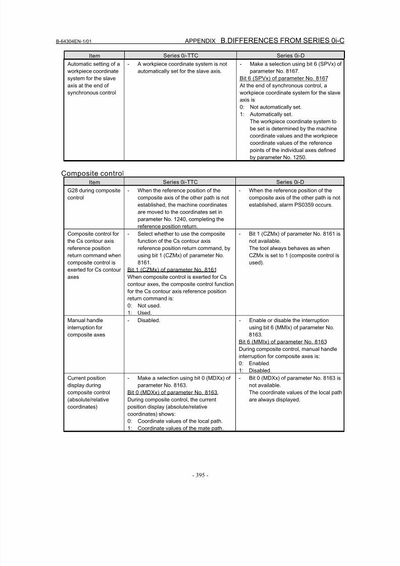
8/16/2019 Manual Operacion para FANUC
http://slidepdf.com/reader/full/manual-operacion-para-fanuc 413/435
B-64304EN-1/01 APPENDIX B.DIFFERENCES FROM SERIES 0i-C
- 395 -
Item Series 0i-TTC Series 0i-D
Automatic setting of a
workpiece coordinate
system for the slave
axis at the end of
synchronous control
- A workpiece coordinate system is not
automatically set for the slave axis.
- Make a selection using bit 6 (SPVx) of
parameter No. 8167.
Bit 6 (SPVx) of parameter No. 8167
At the end of synchronous control, a
workpiece coordinate system for the slave
axis is:
0: Not automatically set.
1: Automatically set.
The workpiece coordinate system to
be set is determined by the machine
coordinate values and the workpiece
coordinate values of the reference
points of the individual axes defined
by parameter No. 1250.
Composite controlItem Series 0i-TTC Series 0i-D
G28 during composite
control
- When the reference position of the
composite axis of the other path is not
established, the machine coordinates
are moved to the coordinates set in
parameter No. 1240, completing the
reference position return.
- When the reference position of the
composite axis of the other path is not
established, alarm PS0359 occurs.
Composite control for
the Cs contour axis
reference position
return command when
composite control is
exerted for Cs contour
axes
- Select whether to use the composite
function of the Cs contour axis
reference position return command, by
using bit 1 (CZMx) of parameter No.
8161.
Bit 1 (CZMx) of parameter No. 8161
When composite control is exerted for Cs
contour axes, the composite control function
for the Cs contour axis reference position
return command is:
0: Not used.
1: Used.
- Bit 1 (CZMx) of parameter No. 8161 is
not available.
The tool always behaves as when
CZMx is set to 1 (composite control is
used).
Manual handle
interruption for
composite axes
- Disabled. - Enable or disable the interruption
using bit 6 (MMIx) of parameter No.
8163.
Bit 6 (MMIx) of parameter No. 8163
During composite control, manual handle
interruption for composite axes is:0: Enabled.
1: Disabled.
Current position
display during
composite control
(absolute/relative
coordinates)
- Make a selection using bit 0 (MDXx) of
parameter No. 8163.
Bit 0 (MDXx) of parameter No. 8163.
During composite control, the current
position display (absolute/relative
coordinates) shows:
0: Coordinate values of the local path.
1: Coordinate values of the mate path.
- Bit 0 (MDXx) of parameter No. 8163 is
not available.
The coordinate values of the local path
are always displayed.
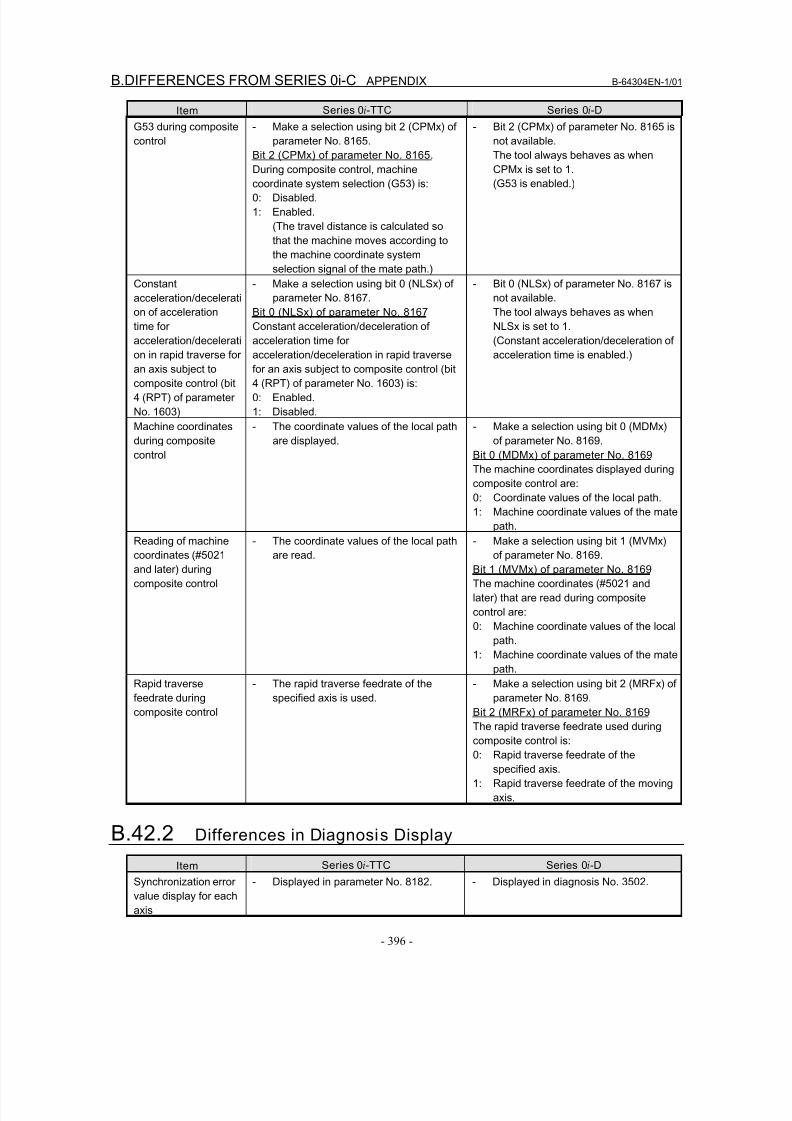
8/16/2019 Manual Operacion para FANUC
http://slidepdf.com/reader/full/manual-operacion-para-fanuc 414/435
B.DIFFERENCES FROM SERIES 0i-C APPENDIX B-64304EN-1/01
- 396 -
Item Series 0i-TTC Series 0i-D
G53 during composite
control
- Make a selection using bit 2 (CPMx) of
parameter No. 8165.
Bit 2 (CPMx) of parameter No. 8165.
During composite control, machine
coordinate system selection (G53) is:
0: Disabled.
1: Enabled.
(The travel distance is calculated so
that the machine moves according to
the machine coordinate system
selection signal of the mate path.)
- Bit 2 (CPMx) of parameter No. 8165 is
not available.
The tool always behaves as when
CPMx is set to 1.
(G53 is enabled.)
Constant
acceleration/decelerati
on of acceleration
time for
acceleration/decelerati
on in rapid traverse foran axis subject to
composite control (bit
4 (RPT) of parameter
No. 1603)
- Make a selection using bit 0 (NLSx) of
parameter No. 8167.
Bit 0 (NLSx) of parameter No. 8167
Constant acceleration/deceleration of
acceleration time for
acceleration/deceleration in rapid traversefor an axis subject to composite control (bit
4 (RPT) of parameter No. 1603) is:
0: Enabled.
1: Disabled.
- Bit 0 (NLSx) of parameter No. 8167 is
not available.
The tool always behaves as when
NLSx is set to 1.
(Constant acceleration/deceleration of
acceleration time is enabled.)
Machine coordinates
during composite
control
- The coordinate values of the local path
are displayed.
- Make a selection using bit 0 (MDMx)
of parameter No. 8169.
Bit 0 (MDMx) of parameter No. 8169
The machine coordinates displayed during
composite control are:
0: Coordinate values of the local path.
1: Machine coordinate values of the mate
path.Reading of machine
coordinates (#5021
and later) during
composite control
- The coordinate values of the local path
are read.
- Make a selection using bit 1 (MVMx)
of parameter No. 8169.
Bit 1 (MVMx) of parameter No. 8169
The machine coordinates (#5021 and
later) that are read during composite
control are:
0: Machine coordinate values of the local
path.
1: Machine coordinate values of the mate
path.
Rapid traverse
feedrate during
composite control
- The rapid traverse feedrate of the
specified axis is used.
- Make a selection using bit 2 (MRFx) of
parameter No. 8169.
Bit 2 (MRFx) of parameter No. 8169
The rapid traverse feedrate used during
composite control is:
0: Rapid traverse feedrate of the
specified axis.
1: Rapid traverse feedrate of the moving
axis.
B.42.2 Differences in Diagnosis Display
Item Series 0i-TTC Series 0i-D
Synchronization errorvalue display for each
axis
- Displayed in parameter No. 8182. - Displayed in diagnosis No. 3502.
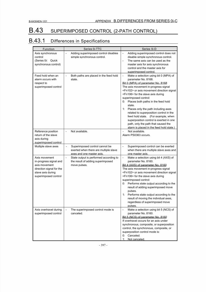
8/16/2019 Manual Operacion para FANUC
http://slidepdf.com/reader/full/manual-operacion-para-fanuc 415/435
B-64304EN-1/01 APPENDIX B.DIFFERENCES FROM SERIES 0i-C
- 397 -
B.43 SUPERIMPOSED CONTROL (2-PATH CONTROL)
B.43.1 Differences in Specifications
Function Series 0i-TTC Series 0i-D
Axis synchronous
control
(Series 0i: Quick
synchronous control)
- Adding superimposed control disables
simple synchronous control.
- Adding superimposed control does not
disable simple synchronous control.
- The same axis can be used as the
master axis for axis synchronous
control and the master axis for
superimposed control.
Feed hold when an
alarm occurs with
respect to
superimposed control
- Both paths are placed in the feed hold
state.
- Make a selection using bit 0 (MPA) of
parameter No. 8168.
Bit 0 (MPA) of parameter No. 8168
The axis movement in-progress signal
<Fn102> or axis movement direction signal<Fn106> for the slave axis during
superimposed control:
0: Places both paths in the feed hold
state.
1: Places only the path including axes
related to superposition control in the
feed hold state. (For example, when
superposition control is exerted in one
path, only the path that caused the
alarm is placed in the feed hold state.)
Reference position
return of the slave
axis during
superimposed control
- Not available. - Not available.
Alarm PS0363 occurs.
Multiple slave axes - Superimposed control cannot be
exerted when there are multiple slave
axes and one master axis.
- Superimposed control can be exerted
when there are multiple slave axes and
one master axis.
Axis movement
in-progress signal and
axis movement
direction signal for the
slave axis during
superimposed control
- State output is performed according to
the result of adding superimposed
move pulses.
- Make a selection using bit 4 (AXS) of
parameter No. 8160.
Bit 4 (AXS) of parameter No. 8160
The axis movement in-progress signal
<Fn102> or axis movement direction signal
<Fn106> for the slave axis during
superimposed control:
0: Performs state output according to theresult of adding superimposed move
pulses.
1: Performs state output according to the
result of moving the individual axes,
regardless of superimposed move
pulses.
Axis overtravel during
superimposed control
- The superimposed control mode is
canceled.
- Make a selection using bit 5 (NCS) of
parameter No. 8160.
Bit 5 (NCS) of parameter No. 8160
If overtravel occurs for an axis under
synchronous, composite, or superposition
control, the synchronous, composite, orsuperposition control mode is:
0: Canceled.
1: Not canceled.
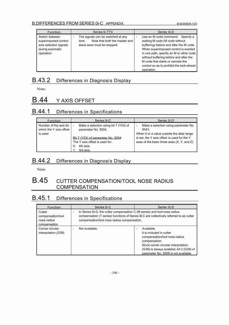
8/16/2019 Manual Operacion para FANUC
http://slidepdf.com/reader/full/manual-operacion-para-fanuc 416/435
B.DIFFERENCES FROM SERIES 0i-C APPENDIX B-64304EN-1/01
- 398 -
Function Series 0i-TTC Series 0i-D
Switch between
superimposed control
axis selection signals
during automatic
operation
- The signals can be switched at any
time. Note that both the master and
slave axes must be stopped.
- Use an M code command. Specify a
waiting M code (M code without
buffering) before and after the M code.
When superimposed control is exerted
in one path, specify an M or other code
without buffering before and after the
M code that starts or cancels the
control so as to prohibit the look-ahead
operation.
B.43.2 Differences in Diagnosis Display
None.
B.44 Y AXIS OFFSET
B.44.1 Differences in Specifications
Function Series 0i-C Series 0i-D
Number of the axis for
which the Y axis offset
is used
- Make a selection using bit 7 (Y03) of
parameter No. 5004.
Bit 7 (Y03) of parameter No. 5004
The Y axis offset is used for:
0: 4th axis.
1: 3rd axis.
- Make a selection using parameter No.
5043.
When 0 or a value outside the data range
is set, the Y axis offset is used for the Y
axes of the basic three axes (X, Y, and Z).
B.44.2 Differences in Diagnosis Display
None.
B.45 CUTTER COMPENSATION/TOOL NOSE RADIUSCOMPENSATION
B.45.1 Differences in Specifications
Function Series 0i-C Series 0i-D
Cutter
compensation/tool
nose radius
compensation
- In Series 0i-D, the cutter compensation C (M series) and tool-nose radius
compensation (T series) functions of Series 0i-C are collectively referred to as cutter
compensation/tool nose radius compensation.
Corner circular
interpolation (G39)
- Not available. - Available.
It is included in cutter
compensation/tool nose radius
compensation.
Since corner circular interpolation
(G39) is always enabled, bit 2 (G39) of
parameter No. 5008 is not available.
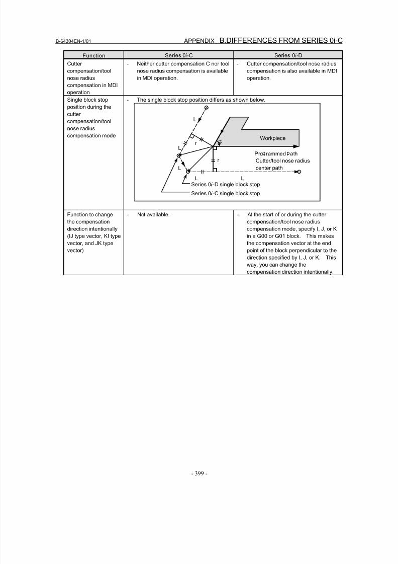
8/16/2019 Manual Operacion para FANUC
http://slidepdf.com/reader/full/manual-operacion-para-fanuc 417/435
B-64304EN-1/01 APPENDIX B.DIFFERENCES FROM SERIES 0i-C
- 399 -
Function Series 0i-C Series 0i-D
Cutter
compensation/tool
nose radius
compensation in MDI
operation
- Neither cutter compensation C nor tool
nose radius compensation is available
in MDI operation.
- Cutter compensation/tool nose radius
compensation is also available in MDI
operation.
Single block stop
position during the
cutter
compensation/tool
nose radius
compensation mode
- The single block stop position differs as shown below.
Function to change
the compensation
direction intentionally
(IJ type vector, KI type
vector, and JK type
vector)
- Not available. - At the start of or during the cutter
compensation/tool nose radius
compensation mode, specify I, J, or K
in a G00 or G01 block. This makes
the compensation vector at the end
point of the block perpendicular to the
direction specified by I, J, or K. This
way, you can change thecompensation direction intentionally.
Pro rammed ath
L
L L
L
r
r
Cutter/tool nose radius
center pathL
Workpiece
Series 0i-D single block stop
Series 0i-C single block stop
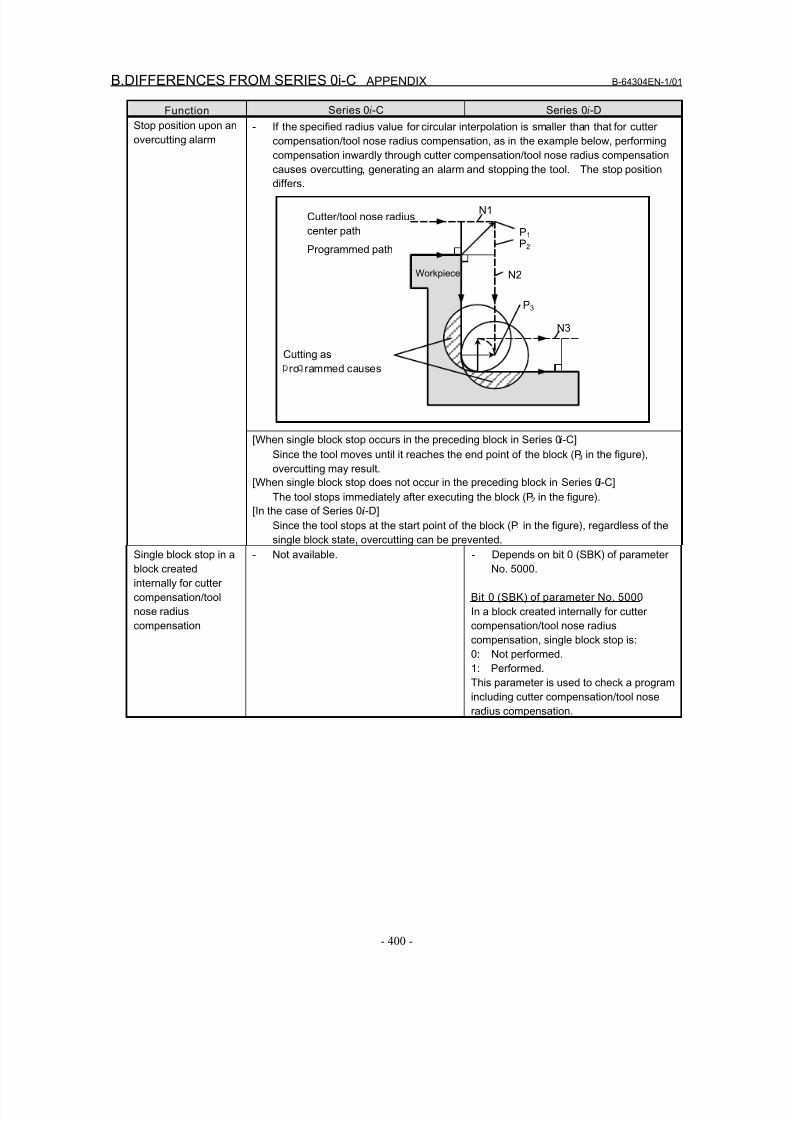
8/16/2019 Manual Operacion para FANUC
http://slidepdf.com/reader/full/manual-operacion-para-fanuc 418/435
B.DIFFERENCES FROM SERIES 0i-C APPENDIX B-64304EN-1/01
- 400 -
Function Series 0i-C Series 0i-D
- If the specified radius value for circular interpolation is smaller than that for cutter
compensation/tool nose radius compensation, as in the example below, performing
compensation inwardly through cutter compensation/tool nose radius compensation
causes overcutting, generating an alarm and stopping the tool. The stop position
differs.
Stop position upon an
overcutting alarm
[When single block stop occurs in the preceding block in Series 0i-C]
Since the tool moves until it reaches the end point of the block (P3 in the figure),
overcutting may result.
[When single block stop does not occur in the preceding block in Series 0i-C]
The tool stops immediately after executing the block (P2 in the figure).
[In the case of Series 0i-D]
Since the tool stops at the start point of the block (P1 in the figure), regardless of thesingle block state, overcutting can be prevented.
Single block stop in a
block created
internally for cutter
compensation/tool
nose radius
compensation
- Not available. - Depends on bit 0 (SBK) of parameter
No. 5000.
Bit 0 (SBK) of parameter No. 5000
In a block created internally for cutter
compensation/tool nose radius
compensation, single block stop is:
0: Not performed.
1: Performed.
This parameter is used to check a program
including cutter compensation/tool nose
radius compensation.
Cutting asro rammed causes
Programmed path
Cutter/tool nose radius
center path
Workpiece
P1
P2
P3
N1
N2
N3
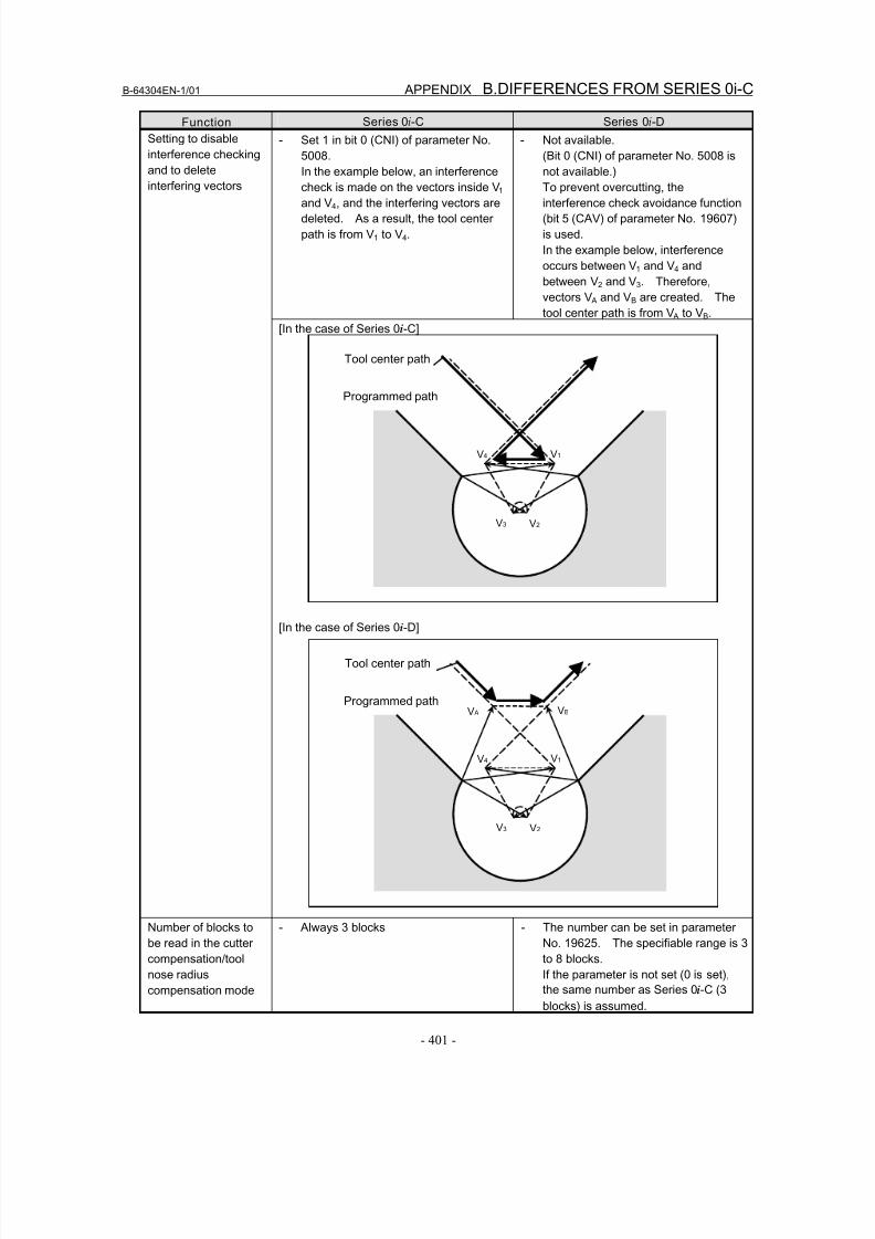
8/16/2019 Manual Operacion para FANUC
http://slidepdf.com/reader/full/manual-operacion-para-fanuc 419/435
B-64304EN-1/01 APPENDIX B.DIFFERENCES FROM SERIES 0i-C
- 401 -
Function Series 0i-C Series 0i-D
- Set 1 in bit 0 (CNI) of parameter No.
5008.
In the example below, an interference
check is made on the vectors inside V1
and V4, and the interfering vectors are
deleted. As a result, the tool center
path is from V1 to V4.
- Not available.
(Bit 0 (CNI) of parameter No. 5008 is
not available.)
To prevent overcutting, the
interference check avoidance function
(bit 5 (CAV) of parameter No. 19607)
is used.
In the example below, interference
occurs between V1 and V4 and
between V2 and V3. Therefore,
vectors V A and VB are created. The
tool center path is from V A to VB.
Setting to disable
interference checking
and to delete
interfering vectors
[In the case of Series 0i-C]
[In the case of Series 0i-D]
Number of blocks to
be read in the cutter
compensation/tool
nose radiuscompensation mode
- Always 3 blocks - The number can be set in parameter
No. 19625. The specifiable range is 3
to 8 blocks.
If the parameter is not set (0 is set),the same number as Series 0i-C (3
blocks) is assumed.
Tool center path
Programmed path
V2V3
V1V4
Tool center path
Programmed pathV A
V2V3
V1
VB
V4

8/16/2019 Manual Operacion para FANUC
http://slidepdf.com/reader/full/manual-operacion-para-fanuc 420/435
B.DIFFERENCES FROM SERIES 0i-C APPENDIX B-64304EN-1/01
- 402 -
Function Series 0i-C Series 0i-D
When circular
interpolation is
specified that causes
the center to coincide
with the start or end
point during the cutter
compensation/tool
nose radius
compensation mode
- Alarm PS0038 is issued, and the tool
stops at the end point of the block
preceding the circular interpolation
block.
- Alarm PS0041 is issued, and the tool
stops at the start point of the block
preceding the circular interpolation
block.
- Depends on bit 2 (CCN) of parameter
No. 5003.
- Bit 2 (CCN) of parameter No. 5003 is
not available. The tool always
behaves as when CCN is set to 1.
Behavior when
automatic reference
position return is
specified during the
cutter
compensation/tool
nose radius
compensation mode
[When CCN = 0]
The offset vector is canceled when the tool moves to the middle point.
Also, the start-up operation is performed from the reference position.
[When CCN = 1 or for Series 0i-D]The offset vector is not canceled when the tool moves to the middle point; it is
canceled when the tool moves to the reference position.
Also, the tool moves from the reference position to the next intersection point.
S S
S
S
r
(G42 G01)
Intermediate
point
G28
G00
G01
Reference position
S S
S
S
r
(G42 G01)
Intermediate
point
G28
G00
G01
Reference position
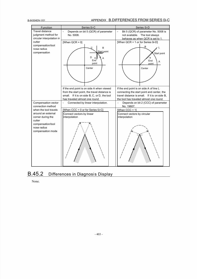
8/16/2019 Manual Operacion para FANUC
http://slidepdf.com/reader/full/manual-operacion-para-fanuc 421/435
B-64304EN-1/01 APPENDIX B.DIFFERENCES FROM SERIES 0i-C
- 403 -
Function Series 0i-C Series 0i-D
- Depends on bit 5 (QCR) of parameter
No. 5008.
- Bit 5 (QCR) of parameter No. 5008 is
not available. The tool always
behaves as when QCR is set to 1.
[When QCR = 0] [When QCR = 1 or for Series 0i-D]
Travel distance
judgment method for
circular interpolation in
cutter
compensation/tool
nose radius
compensation
If the end point is on side A when viewed
from the start point, the travel distance is
small. If it is on side B, C, or D, the tool
has traveled almost one round.
If the end point is on side A of line L
connecting the start point and center, the
travel distance is small. If it is on side B,
the tool has traveled almost one round.
- Connected by linear interpolation. - Depends on bit 2 (CCC) of parameter
No. 19607.
Compensation vector
connection method
when the tool travels
around an external
corner during the
cutter
compensation/tool
nose radius
compensation mode
[When CCC = 0 or for Series 0i-C]
Connect vectors by linearinterpolation
[When CCC = 1]
Connect vectors by circularinterpolation
B.45.2 Differences in Diagnosis Display None.
C
A
B
Start point
End
point
Center
D
A
B L
Start point
End
point
Center
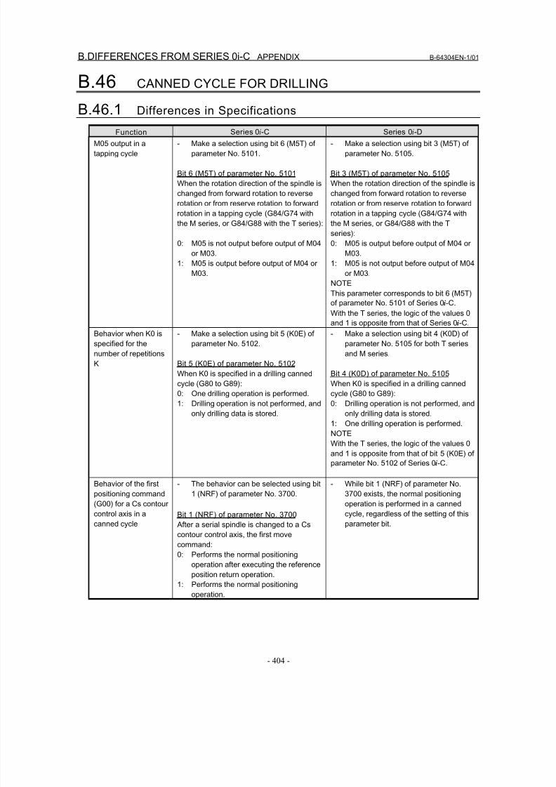
8/16/2019 Manual Operacion para FANUC
http://slidepdf.com/reader/full/manual-operacion-para-fanuc 422/435
B.DIFFERENCES FROM SERIES 0i-C APPENDIX B-64304EN-1/01
- 404 -
B.46 CANNED CYCLE FOR DRILLING
B.46.1 Differences in Specifications
Function Series 0i-C Series 0i-D
M05 output in a
tapping cycle
- Make a selection using bit 6 (M5T) of
parameter No. 5101.
Bit 6 (M5T) of parameter No. 5101
When the rotation direction of the spindle is
changed from forward rotation to reverse
rotation or from reserve rotation to forward
rotation in a tapping cycle (G84/G74 with
the M series, or G84/G88 with the T series):
0: M05 is not output before output of M04or M03.
1: M05 is output before output of M04 or
M03.
- Make a selection using bit 3 (M5T) of
parameter No. 5105.
Bit 3 (M5T) of parameter No. 5105
When the rotation direction of the spindle is
changed from forward rotation to reverse
rotation or from reserve rotation to forward
rotation in a tapping cycle (G84/G74 with
the M series, or G84/G88 with the T
series):
0: M05 is output before output of M04 orM03.
1: M05 is not output before output of M04
or M03.
NOTE
This parameter corresponds to bit 6 (M5T)
of parameter No. 5101 of Series 0i-C.
With the T series, the logic of the values 0
and 1 is opposite from that of Series 0i-C.
Behavior when K0 is
specified for the
number of repetitions
K
- Make a selection using bit 5 (K0E) of
parameter No. 5102.
Bit 5 (K0E) of parameter No. 5102
When K0 is specified in a drilling canned
cycle (G80 to G89):
0: One drilling operation is performed.
1: Drilling operation is not performed, and
only drilling data is stored.
- Make a selection using bit 4 (K0D) of
parameter No. 5105 for both T series
and M series.
Bit 4 (K0D) of parameter No. 5105
When K0 is specified in a drilling canned
cycle (G80 to G89):
0: Drilling operation is not performed, and
only drilling data is stored.
1: One drilling operation is performed.
NOTE
With the T series, the logic of the values 0
and 1 is opposite from that of bit 5 (K0E) of
parameter No. 5102 of Series 0i-C.
Behavior of the first
positioning command(G00) for a Cs contour
control axis in a
canned cycle
- The behavior can be selected using bit
1 (NRF) of parameter No. 3700.
Bit 1 (NRF) of parameter No. 3700
After a serial spindle is changed to a Cs
contour control axis, the first move
command:
0: Performs the normal positioning
operation after executing the reference
position return operation.
1: Performs the normal positioning
operation.
- While bit 1 (NRF) of parameter No.
3700 exists, the normal positioningoperation is performed in a canned
cycle, regardless of the setting of this
parameter bit.
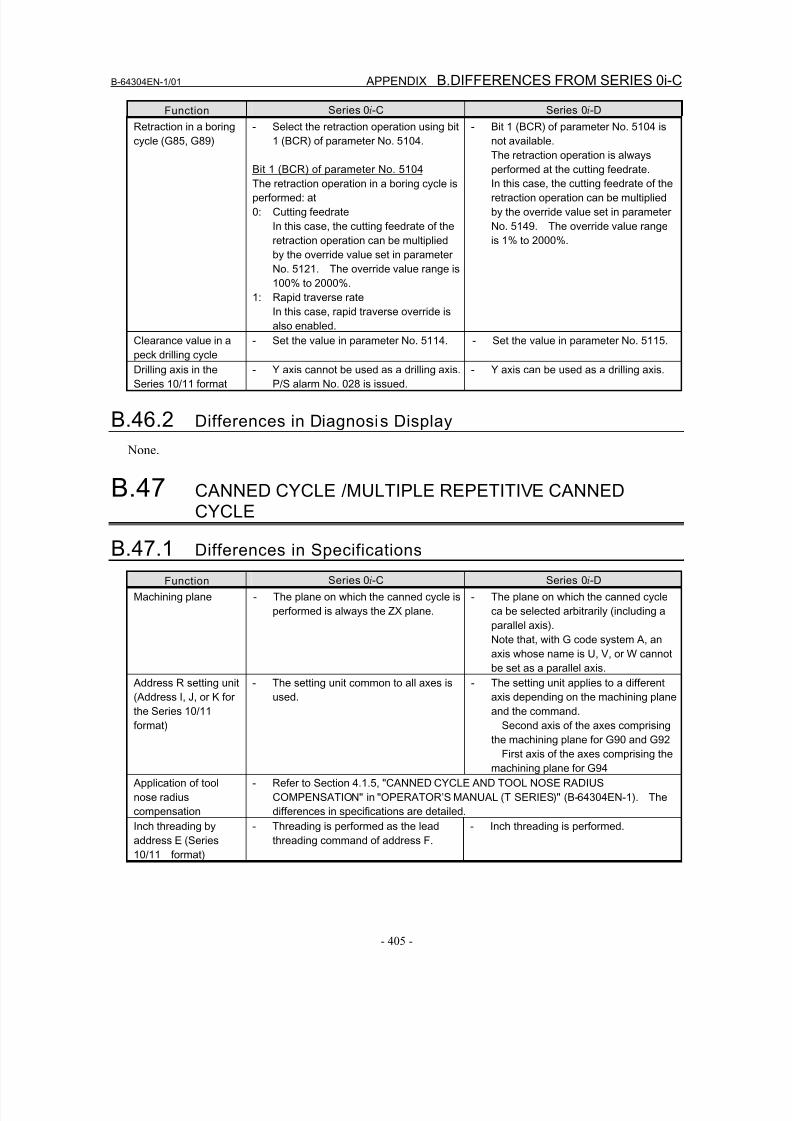
8/16/2019 Manual Operacion para FANUC
http://slidepdf.com/reader/full/manual-operacion-para-fanuc 423/435
B-64304EN-1/01 APPENDIX B.DIFFERENCES FROM SERIES 0i-C
- 405 -
Function Series 0i-C Series 0i-D
Retraction in a boring
cycle (G85, G89)
- Select the retraction operation using bit
1 (BCR) of parameter No. 5104.
Bit 1 (BCR) of parameter No. 5104
The retraction operation in a boring cycle is
performed: at
0: Cutting feedrate
In this case, the cutting feedrate of the
retraction operation can be multiplied
by the override value set in parameter
No. 5121. The override value range is
100% to 2000%.
1: Rapid traverse rate
In this case, rapid traverse override is
also enabled.
- Bit 1 (BCR) of parameter No. 5104 is
not available.
The retraction operation is always
performed at the cutting feedrate.
In this case, the cutting feedrate of the
retraction operation can be multiplied
by the override value set in parameter
No. 5149. The override value range
is 1% to 2000%.
Clearance value in a
peck drilling cycle
- Set the value in parameter No. 5114. - Set the value in parameter No. 5115.
Drilling axis in the
Series 10/11 format
- Y axis cannot be used as a drilling axis.
P/S alarm No. 028 is issued.
- Y axis can be used as a drilling axis.
B.46.2 Differences in Diagnosis Display
None.
B.47 CANNED CYCLE /MULTIPLE REPETITIVE CANNEDCYCLE
B.47.1 Differences in Specifications
Function Series 0i-C Series 0i-D
Machining plane - The plane on which the canned cycle is
performed is always the ZX plane.
- The plane on which the canned cycle
ca be selected arbitrarily (including a
parallel axis).
Note that, with G code system A, an
axis whose name is U, V, or W cannot
be set as a parallel axis.
Address R setting unit
(Address I, J, or K for
the Series 10/11
format)
- The setting unit common to all axes is
used.
- The setting unit applies to a different
axis depending on the machining plane
and the command.
Second axis of the axes comprising
the machining plane for G90 and G92
First axis of the axes comprising the
machining plane for G94
Application of tool
nose radius
compensation
- Refer to Section 4.1.5, "CANNED CYCLE AND TOOL NOSE RADIUS
COMPENSATION" in "OPERATOR’S MANUAL (T SERIES)" (B-64304EN-1). The
differences in specifications are detailed.
Inch threading by
address E (Series
10/11 format)
- Threading is performed as the lead
threading command of address F.
- Inch threading is performed.
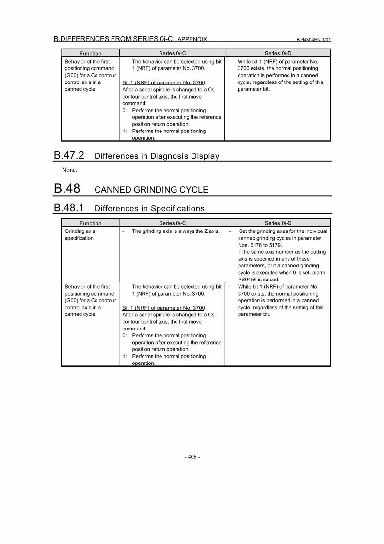
8/16/2019 Manual Operacion para FANUC
http://slidepdf.com/reader/full/manual-operacion-para-fanuc 424/435
B.DIFFERENCES FROM SERIES 0i-C APPENDIX B-64304EN-1/01
- 406 -
Function Series 0i-C Series 0i-D
Behavior of the first
positioning command
(G00) for a Cs contour
control axis in a
canned cycle
- The behavior can be selected using bit
1 (NRF) of parameter No. 3700.
Bit 1 (NRF) of parameter No. 3700 After a serial spindle is changed to a Cs
contour control axis, the first move
command:
0: Performs the normal positioning
operation after executing the reference
position return operation.
1: Performs the normal positioning
operation.
- While bit 1 (NRF) of parameter No.
3700 exists, the normal positioning
operation is performed in a canned
cycle, regardless of the setting of this
parameter bit.
B.47.2 Differences in Diagnosis Display
None.
B.48 CANNED GRINDING CYCLE
B.48.1 Differences in Specifications
Function Series 0i-C Series 0i-D
Grinding axis
specification
- The grinding axis is always the Z axis. - Set the grinding axes for the individual
canned grinding cycles in parameter
Nos. 5176 to 5179.
If the same axis number as the cutting
axis is specified in any of these
parameters, or if a canned grinding
cycle is executed when 0 is set, alarm
PS0456 is issued.
Behavior of the first
positioning command
(G00) for a Cs contour
control axis in a
canned cycle
- The behavior can be selected using bit
1 (NRF) of parameter No. 3700.
Bit 1 (NRF) of parameter No. 3700
After a serial spindle is changed to a Cs
contour control axis, the first move
command:
0: Performs the normal positioning
operation after executing the referenceposition return operation.
1: Performs the normal positioning
operation.
- While bit 1 (NRF) of parameter No.
3700 exists, the normal positioning
operation is performed in a canned
cycle, regardless of the setting of this
parameter bit.
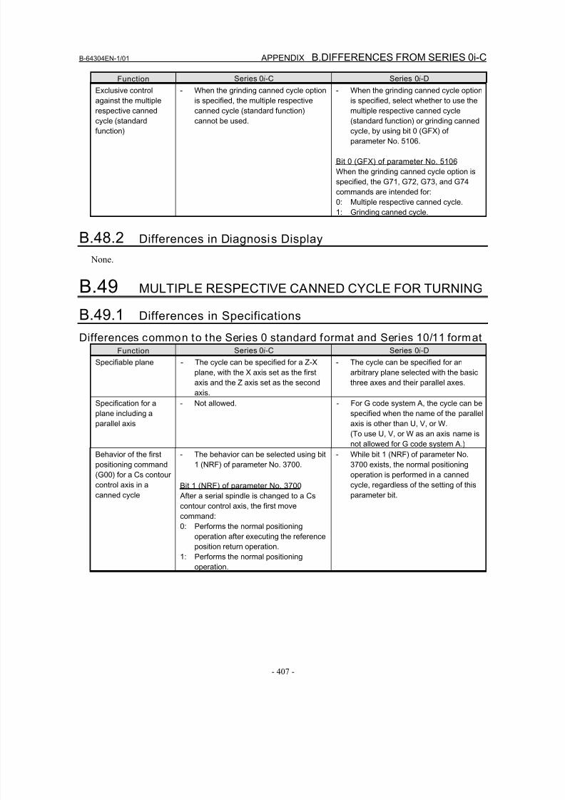
8/16/2019 Manual Operacion para FANUC
http://slidepdf.com/reader/full/manual-operacion-para-fanuc 425/435
B-64304EN-1/01 APPENDIX B.DIFFERENCES FROM SERIES 0i-C
- 407 -
Function Series 0i-C Series 0i-D
Exclusive control
against the multiple
respective canned
cycle (standard
function)
- When the grinding canned cycle option
is specified, the multiple respective
canned cycle (standard function)
cannot be used.
- When the grinding canned cycle option
is specified, select whether to use the
multiple respective canned cycle
(standard function) or grinding canned
cycle, by using bit 0 (GFX) of
parameter No. 5106.
Bit 0 (GFX) of parameter No. 5106
When the grinding canned cycle option is
specified, the G71, G72, G73, and G74
commands are intended for:
0: Multiple respective canned cycle.
1: Grinding canned cycle.
B.48.2 Differences in Diagnosis Display
None.
B.49 MULTIPLE RESPECTIVE CANNED CYCLE FOR TURNING
B.49.1 Differences in Specifications
Differences common to the Series 0 standard format and Series 10/11 formatFunction Series 0i-C Series 0i-D
Specifiable plane - The cycle can be specified for a Z-X
plane, with the X axis set as the first
axis and the Z axis set as the second
axis.
- The cycle can be specified for an
arbitrary plane selected with the basic
three axes and their parallel axes.
Specification for a
plane including a
parallel axis
- Not allowed. - For G code system A, the cycle can be
specified when the name of the parallel
axis is other than U, V, or W.
(To use U, V, or W as an axis name is
not allowed for G code system A.)
Behavior of the first
positioning command
(G00) for a Cs contour
control axis in a
canned cycle
- The behavior can be selected using bit
1 (NRF) of parameter No. 3700.
Bit 1 (NRF) of parameter No. 3700
After a serial spindle is changed to a Cs
contour control axis, the first move
command:
0: Performs the normal positioning
operation after executing the reference
position return operation.
1: Performs the normal positioning
operation.
- While bit 1 (NRF) of parameter No.
3700 exists, the normal positioning
operation is performed in a canned
cycle, regardless of the setting of this
parameter bit.
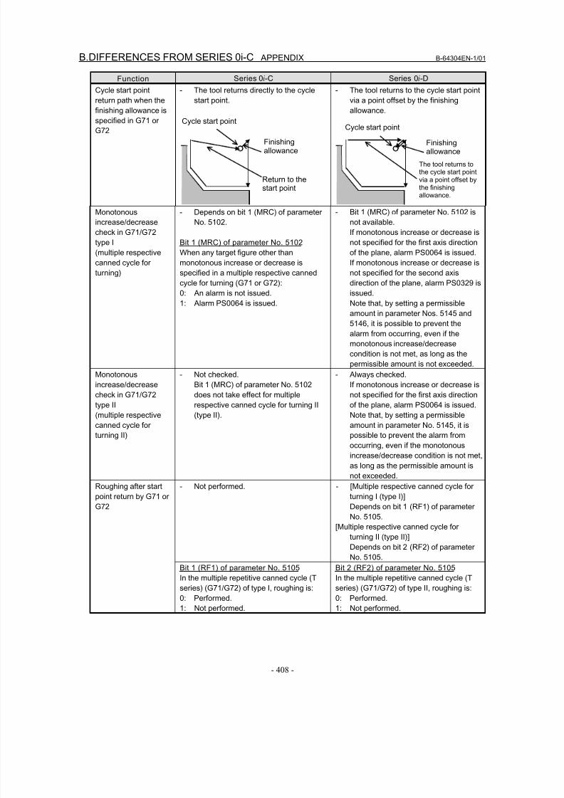
8/16/2019 Manual Operacion para FANUC
http://slidepdf.com/reader/full/manual-operacion-para-fanuc 426/435
B.DIFFERENCES FROM SERIES 0i-C APPENDIX B-64304EN-1/01
- 408 -
Function Series 0i-C Series 0i-D
Cycle start point
return path when the
finishing allowance is
specified in G71 or
G72
- The tool returns directly to the cycle
start point.
Finishingallowance
Return to thestart point
Cycle start point
- The tool returns to the cycle start point
via a point offset by the finishing
allowance.
Finishingallowance
Cycle start point
The tool returns tothe cycle start pointvia a point offset bythe finishing allowance.
Monotonous
increase/decrease
check in G71/G72
type I
(multiple respectivecanned cycle for
turning)
- Depends on bit 1 (MRC) of parameter
No. 5102.
Bit 1 (MRC) of parameter No. 5102
When any target figure other thanmonotonous increase or decrease is
specified in a multiple respective canned
cycle for turning (G71 or G72):
0: An alarm is not issued.
1: Alarm PS0064 is issued.
- Bit 1 (MRC) of parameter No. 5102 is
not available.
If monotonous increase or decrease is
not specified for the first axis direction
of the plane, alarm PS0064 is issued.If monotonous increase or decrease is
not specified for the second axis
direction of the plane, alarm PS0329 is
issued.
Note that, by setting a permissible
amount in parameter Nos. 5145 and
5146, it is possible to prevent the
alarm from occurring, even if the
monotonous increase/decrease
condition is not met, as long as the
permissible amount is not exceeded.
Monotonousincrease/decrease
check in G71/G72
type II
(multiple respective
canned cycle for
turning II)
- Not checked.Bit 1 (MRC) of parameter No. 5102
does not take effect for multiple
respective canned cycle for turning II
(type II).
- Always checked.If monotonous increase or decrease is
not specified for the first axis direction
of the plane, alarm PS0064 is issued.
Note that, by setting a permissible
amount in parameter No. 5145, it is
possible to prevent the alarm from
occurring, even if the monotonous
increase/decrease condition is not met,
as long as the permissible amount is
not exceeded.
- Not performed. - [Multiple respective canned cycle for
turning I (type I)]
Depends on bit 1 (RF1) of parameter
No. 5105.
[Multiple respective canned cycle for
turning II (type II)]
Depends on bit 2 (RF2) of parameter
No. 5105.
Roughing after start
point return by G71 or
G72
Bit 1 (RF1) of parameter No. 5105
In the multiple repetitive canned cycle (T
series) (G71/G72) of type I, roughing is:
0: Performed.
1: Not performed.
Bit 2 (RF2) of parameter No. 5105
In the multiple repetitive canned cycle (T
series) (G71/G72) of type II, roughing is:
0: Performed.
1: Not performed.
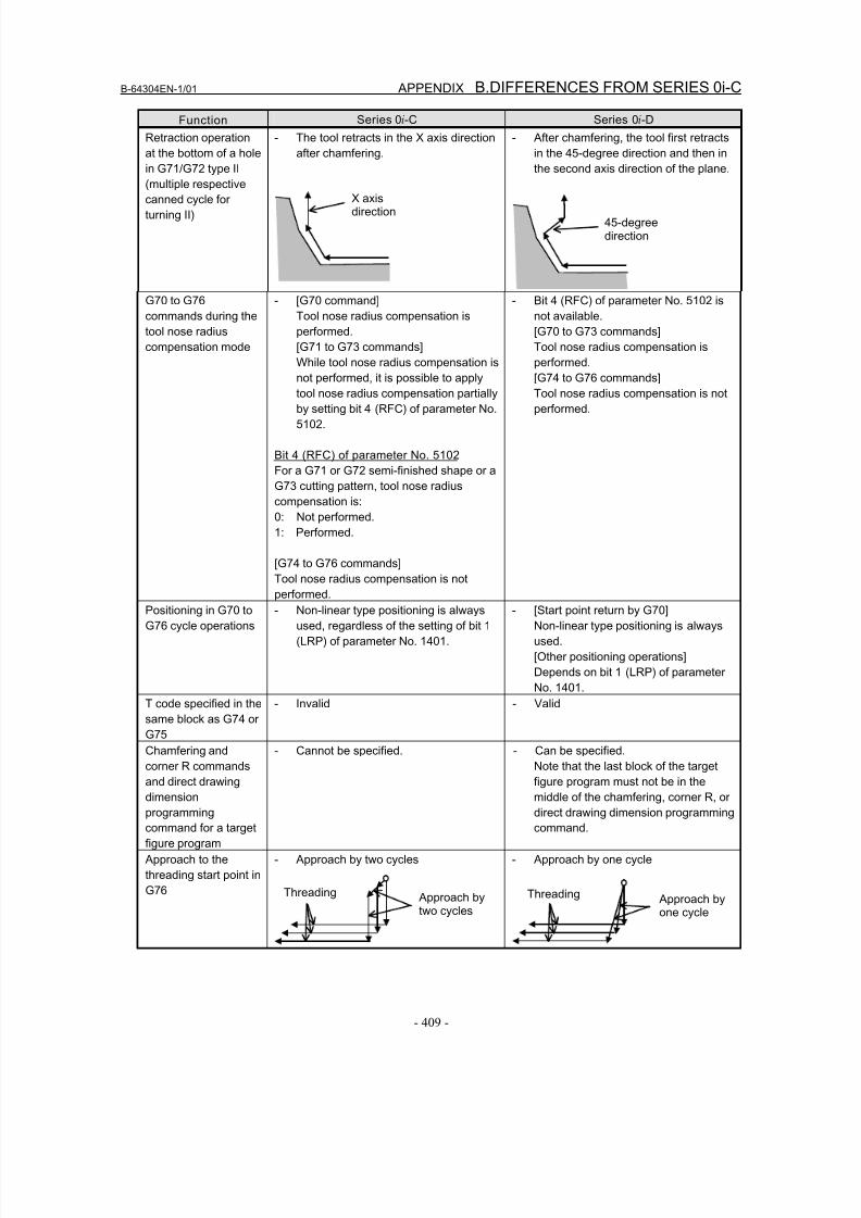
8/16/2019 Manual Operacion para FANUC
http://slidepdf.com/reader/full/manual-operacion-para-fanuc 427/435
B-64304EN-1/01 APPENDIX B.DIFFERENCES FROM SERIES 0i-C
- 409 -
Function Series 0i-C Series 0i-D
Retraction operation
at the bottom of a hole
in G71/G72 type II
(multiple respective
canned cycle for
turning II)
- The tool retracts in the X axis direction
after chamfering.
X axisdirection
- After chamfering, the tool first retracts
in the 45-degree direction and then in
the second axis direction of the plane.
45-degreedirection
G70 to G76
commands during the
tool nose radius
compensation mode
- [G70 command]
Tool nose radius compensation is
performed.
[G71 to G73 commands]
While tool nose radius compensation is
not performed, it is possible to applytool nose radius compensation partially
by setting bit 4 (RFC) of parameter No.
5102.
Bit 4 (RFC) of parameter No. 5102
For a G71 or G72 semi-finished shape or a
G73 cutting pattern, tool nose radius
compensation is:
0: Not performed.
1: Performed.
[G74 to G76 commands]
Tool nose radius compensation is not
performed.
- Bit 4 (RFC) of parameter No. 5102 is
not available.
[G70 to G73 commands]
Tool nose radius compensation is
performed.
[G74 to G76 commands]Tool nose radius compensation is not
performed.
Positioning in G70 to
G76 cycle operations
- Non-linear type positioning is always
used, regardless of the setting of bit 1
(LRP) of parameter No. 1401.
- [Start point return by G70]
Non-linear type positioning is always
used.
[Other positioning operations]
Depends on bit 1 (LRP) of parameter
No. 1401.
T code specified in the
same block as G74 or
G75
- Invalid - Valid
Chamfering and
corner R commandsand direct drawing
dimension
programming
command for a target
figure program
- Cannot be specified. - Can be specified.
Note that the last block of the targetfigure program must not be in the
middle of the chamfering, corner R, or
direct drawing dimension programming
command.
Approach to the
threading start point in
G76
- Approach by two cycles
Approach bytwo cycles
Threading
- Approach by one cycle
Approach byone cycle
Threading
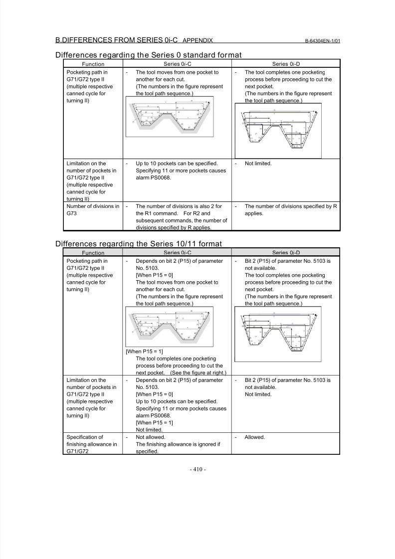
8/16/2019 Manual Operacion para FANUC
http://slidepdf.com/reader/full/manual-operacion-para-fanuc 428/435
B.DIFFERENCES FROM SERIES 0i-C APPENDIX B-64304EN-1/01
- 410 -
Differences regarding the Series 0 standard formatFunction Series 0i-C Series 0i-D
Pocketing path in
G71/G72 type II
(multiple respectivecanned cycle for
turning II)
- The tool moves from one pocket to
another for each cut.
(The numbers in the figure representthe tool path sequence.)
- The tool completes one pocketing
process before proceeding to cut the
next pocket.(The numbers in the figure represent
the tool path sequence.)
Limitation on the
number of pockets in
G71/G72 type II
(multiple respective
canned cycle for
turning II)
- Up to 10 pockets can be specified.
Specifying 11 or more pockets causes
alarm PS0068.
- Not limited.
Number of divisions in
G73
- The number of divisions is also 2 for
the R1 command. For R2 and
subsequent commands, the number of
divisions specified by R applies.
- The number of divisions specified by R
applies.
Differences regarding the Series 10/11 formatFunction Series 0i-C Series 0i-D
Pocketing path inG71/G72 type II
(multiple respective
canned cycle for
turning II)
- Depends on bit 2 (P15) of parameterNo. 5103.
[When P15 = 0]
The tool moves from one pocket to
another for each cut.
(The numbers in the figure represent
the tool path sequence.)
[When P15 = 1]The tool completes one pocketing
process before proceeding to cut the
next pocket. (See the figure at right.)
- Bit 2 (P15) of parameter No. 5103 isnot available.
The tool completes one pocketing
process before proceeding to cut the
next pocket.
(The numbers in the figure represent
the tool path sequence.)
Limitation on the
number of pockets in
G71/G72 type II
(multiple respective
canned cycle for
turning II)
- Depends on bit 2 (P15) of parameter
No. 5103.
[When P15 = 0]
Up to 10 pockets can be specified.
Specifying 11 or more pockets causes
alarm PS0068.
[When P15 = 1]
Not limited.
- Bit 2 (P15) of parameter No. 5103 is
not available.
Not limited.
Specification offinishing allowance in
G71/G72
- Not allowed.The finishing allowance is ignored if
specified.
- Allowed.
8/16/2019 Manual Operacion para FANUC
http://slidepdf.com/reader/full/manual-operacion-para-fanuc 429/435
B-64304EN-1/01 APPENDIX B.DIFFERENCES FROM SERIES 0i-C
- 411 -
Function Series 0i-C Series 0i-D
Number of divisions in
G73
- The number of divisions is also 2 for
the D1 command. For D2 and
subsequent commands, the number of
divisions specified by D applies.
- The number of divisions specified by D
applies.
Address E command
in G76
- Threading is performed as the lead
threading command of address F.
- Inch threading is performed.
B.49.2 Differences in Diagnosis Display
None.
B.50 CHAMFERING AND CORNER ROUNDING
B.50.1 Differences in SpecificationsFunction Series 0i-C Series 0i-D
Chamfering and
corner rounding
commands for a plane
other than the Z-X
plane
- Not available.
Alarm PS0212 is issued.
- Available.
The commands can be specified for
any plane, even one that includes a
parallel axis.
Single block operation - [Chamfering]
Single block stop is not performed at
the start point of an inserted
chamfering block.
[Corner rounding]
Single block stop is performed at the
start point of an inserted corner
rounding block.
- [Common to chamfering and corner
rounding]
Whether to perform single block stop
at the start point of an inserted block
depends on bit 0 (SBC) of parameter
No. 5105.
Bit 0 (SBC) of parameter No. 5105
In a drilling canned cycle, chamfer
cycle/corner rounding (T series) or optional
angle chamfering/corner rounding cycle (M
series):
0: Single block stop is not performed.
1: Single block stop is performed.
B.50.2 Differences in Diagnosis Display
None.
B.51 DIRECT DRAWING DIMENSIONS PROGRAMMING
B.51.1 Differences in Specifications
Function Series 0i-C Series 0i-D
Specification of the
direct drawing
dimension
programmingcommand for a plane
other than the Z-X
plane
- P/S alarm No. 212 is issued. - No alarm is issued.
The command can be specified for a
plane other than the Z-X plane.

8/16/2019 Manual Operacion para FANUC
http://slidepdf.com/reader/full/manual-operacion-para-fanuc 430/435
B.DIFFERENCES FROM SERIES 0i-C APPENDIX B-64304EN-1/01
- 412 -
Function Series 0i-C Series 0i-D
When two or more
blocks not to be
moved exist between
consecutive
commands that
specify direct input of
drawing dimensions
- No alarm is issued. - Alarm PS0312 is issued.
B.51.2 Differences in Diagnosis Display
None.
8/16/2019 Manual Operacion para FANUC
http://slidepdf.com/reader/full/manual-operacion-para-fanuc 431/435
B-64304EN-1/01 INDEX
i-1
INDEX
<Number>
2-PATH CONTROL FUNCTION.................... ...........269
<A>
ADDRESSES AND SPECIFIABLE VALUE RANGE
FOR Series 10/11 PROGRAM FORMAT ...................194
ADVANCED PREVIEW CONTROL........................ .365
ARBITRARY ANGULAR AXIS CONTROL.............371
AUTOMATIC TOOL OFFSET...................................345
AUTOMATIC TOOL OFFSET (G36, G37)................190
AXIS CONTROL FUNCTIONS ...................... ...........260
AXIS SYNCHRONOUS CONTROL........................ ..367
<B>
BALANCE CUT (G68, G69).......................................275
Boring Cycle (G85)......................................................257
Boring Cycle (G89)......................................................258
<C>
CANNED CYCLE....................... ....................... .........195
CANNED CYCLE (G90, G92, G94) ..................... ........29
CANNED CYCLE /MULTIPLE REPETITIVE
CANNED CYCLE....................... ....................... .........405
Canned Cycle and Tool Nose Radius Compensation
................................................................................42,208
Canned Cycle Cancel (G80).........................................101
CANNED CYCLE FOR DRILLING...............78,245,404Canned Cycle for Drilling Cancel (G80) ................90,259
CANNED GRINDING CYCLE.................................. .406
CANNED GRINDING CYCLE (FOR GRINDING
MACHINE)..................................................................103
CHAMFERING AND CORNER R........................ .....112
CHAMFERING AND CORNER ROUNDING...........411
Chuck and Tail Stock Barriers ........................ .............293
CHUCK/TAIL STOCK BARRIER ........................ .....389
CIRCULAR INTERPOLATION ......................... ........347
COMMON MEMORY BETWEEN EACH PATH......270
COMPENSATION FUNCTION..................................124
CONSTANT LEAD THREADING (G32) ....................23CONSTANT SURFACE SPEED CONTROL.............357
CONTINUOUS THREADING......................................27
CORNER CIRCULAR INTERPOLATION (G39)......188
Counter Input of Offset value.......................................289
Cs CONTOUR CONTROL..........................................355
CUSTOM MACRO......................................................361
CUTTER COMPENSATION/TOOL NOSE RADIUS
COMPENSATION.......................................................398
<D>
DATA INPUT/OUTPUT..................... ........................ 279
DATA SERVER FUNCTION ....................... ..............388
DATA TYPE................................................................341
DEFINITION OF WARNING, CAUTION, AND
NOTE...... ...................... ....................... ...................... ...s-1
DESCRIPTION OF PARAMETERS...........................303
DETAILS OF TOOL NOSE RADIUS
COMPENSATION.......................................................141
DIFFERENCES FROM SERIES 0i-C .........................344
DIRECT DRAWING DIMENSION PROGRAMMING
.....................................................................................119
DIRECT DRAWING DIMENSIONS
PROGRAMMING........................................................411
Direct Input of Tool Offset Value ....................... .........285
Direct Input of Tool Offset Value Measured B... .........287
Direction of Imaginary Tool Nose ....................... ........131
Drilling Cycle, Counter Boring (G82)..........................250
Drilling Cycle, Spot Drilling Cycle (G81)...................249
<E>
End Face Peck Drilling Cycle (G74)......... ..............67,234End Face Turning Cycle (G94)...................... .........38,204
EXTERNAL DATA INPUT........................ ................386
EXTERNAL SUBPROGRAM CALL (M198)............379
Extraction override.......................................................101
<F>
Face cutting cycle....................................................38,204
Finishing Cycle (G70).............................................63,230
Front Boring Cycle (G85) / Side Boring Cycle (G89) ...89
Front Drilling Cycle (G83)/Side Drilling Cycle (G87) ..81
FRONT FACE RIGID TAPPING CYCLE (G84) /
SIDE FACE RIGID TAPPING CYCLE (G88)..............91
Front Tapping Cycle (G84) / Side Tapping Cycle
(G88) ...................... ....................... ...................... ...........84
FUNCTIONS TO SIMPLIFY PROGRAMMING.........29
<G>
GENERAL..................... ........................ .....................3,11
GENERAL FLOW OF OPERATION OF CNC
MACHINE TOOL............................................................5
GENERAL WARNINGS AND CAUTIONS ............... s-2
<H>
HELICAL INTERPOLATION ...................... ..............348
High-speed Peck Drilling Cycle (G83.1) .....................253How to Use Canned Cycles..........................................207
How to Use Canned Cycles (G90, G92, G94)................40
<I>
Imaginary Tool Nose....................................................129
INPUT OF TOOL OFFSET VALUE MEASURED B 361
INPUT/OUTPUT ON EACH SCREEN.......................279
INPUT/OUTPUT ON THE ALL IO SCREEN............280
Inputting and Outputting Y-axis Offset Data ........279,280
Inputting Y-axis offset data..........................................279
Interference Check ...................... ........................ .........177
Interference check alarm function................................181
Interference check avoidance function................... ......182
INTERPOLATION FUNCTION........................ ...........16
INTERRUPTION TYPE CUSTOM MACRO.............364
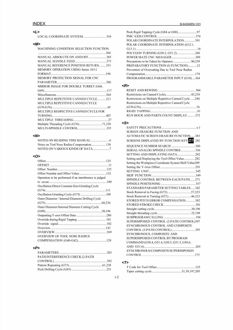
8/16/2019 Manual Operacion para FANUC
http://slidepdf.com/reader/full/manual-operacion-para-fanuc 432/435
INDEX B-64304EN-1/01
i-2
<L>
LOCAL COORDINATE SYSTEM............................ .354
<M>
MACHINING CONDITION SELECTION FUNCTION
.....................................................................................366
MANUAL ABSOLUTE ON AND OFF ......................385
MANUAL HANDLE FEED........................................373
MANUAL REFERENCE POSITION RETURN.........351
MEMORY OPERATION USING Series 10/11
FORMAT.....................................................................194
MEMORY PROTECTION SIGNAL FOR CNC
PARAMETER..............................................................386
MIRROR IMAGE FOR DOUBLE TURRET (G68,
G69) ........................ ....................... ....................... .......117
Miscellaneous...............................................................364
MULTIPLE REPETITIVE CANNED CYCLE.... .......211
MULTIPLE REPETITIVE CANNED CYCLE(G70-G76)......................................................................45
MULTIPLE RESPECTIVE CANNED CYCLE FOR
TURNING....................................................................407
MULTIPLE THREADING............................................27
Multiple Threading Cycle (G76).............................71,238
MULTI-SPINDLE CONTROL....................................355
<N>
NOTES ON READING THIS MANUAL .................... ...6
Notes on Tool Nose Radius Compensation..................138
NOTES ON VARIOUS KINDS OF DATA.....................7
<O>
Offset............................................................................125
OFFSET ..................... ...................... ....................... .......11
Offset Number..............................................................125
Offset Number and Offset Value................................ ..132
Operation to be performed if an interference is judged
to occur.........................................................................180
Oscillation Direct Constant-Size Grinding Cycle
(G74)............................................................................111
Oscillation Grinding Cycle (G73) ....................... .........109
Outer Diameter / Internal Diameter Drilling Cycle
(G75).......................................................................68,236
Outer Diameter/Internal Diameter Cutting Cycle(G90).......................................................................30,196
Outputting Y-axis Offset Data ....................... ..............280
Override during Rigid Tapping ....................... .............101
Override signal.............................................................102
Overview......................................................................141
OVERVIEW ..................... ....................... ....................269
OVERVIEW OF TOOL NOSE RADIUS
COMPENSATION (G40-G42)....................................129
<P>
PARAMETERS.................... ....................... ................303
PATH INTERFERENCE CHECK (2-PATH
CONTROL) ...................... ....................... ....................392
Pattern Repeating (G73)..........................................61,228
Peck Drilling Cycle (G83) .................... ....................... 251
Peck Rigid Tapping Cycle (G84 or G88).......................97
PMC AXIS CONTROL ....................... ........................374
POLAR COORDINATE INTERPOLATION..............391
POLAR COORDINATE INTERPOLATION (G12.1,
G13.1) .................... ....................... ...................... ...........16
POLYGON TURNING (G50.2, G51.2).................. .....260
POWER MATE CNC MANAGER ........................ .....389
Precautions to be Taken by Operator ......................90,259
PREPARATORY FUNCTION (G FUNCTION)...........12
Prevention of Overcutting Due to Tool Nose Radius
Compensation...............................................................174
PROGRAMMABLE PARAMETER INPUT (G10) ....364
<R>
RESET AND REWIND....................... ........................384
Restrictions on Canned Cycles................................43,210
Restrictions on Multiple Repetitive Canned Cycle ......244
Restrictions on Multiple Repetitive Canned Cycle(G70-G76)......................................................................76
RIGID TAPPING...........................................................91
RUN HOUR AND PARTS COUNT DISPLAY....... ...372
<S>
SAFETY PRECAUTIONS .................... ....................... s-1
SCREEN ERASURE FUNCTION AND
AUTOMATIC SCREEN ERASURE FUNCTION......383
SCREENS DISPLAYED BY FUNCTION KEY 282
SEQUENCE NUMBER SEARCH ......................... .....380
SERIAL/ANALOG SPINDLE CONTROL .................356
SETTING AND DISPLAYING DATA.......................282Setting and Displaying the Tool Offset Value..............282
Setting the Workpiece Coordinate System Shift Value289
Setting the Y-Axis Offset.............................................291
SETTING UNIT...........................................................345
SKIP FUNCTION........................................................349
SPINDLE CONTROL BETWEEN EACH PATH.......271
SPINDLE POSITIONING ....................... ....................357
STANDARD PARAMETER SETTING TABLES......342
Stock Removal in Facing (G72)..............................57,223
Stock Removal in Turning (G71) ....................... .....46,212
STORED PITCH ERROR COMPENSATION............382
STORED STROKE CHECK ....................... ................381
Straight cutting cycle...............................................30,196
Straight threading cycle...........................................32,198
SUBPROGRAM CALLING........................ ................194
SUPERIMPOSED CONTROL (2-PATH CONTROL)397
SYNCHRONOUS CONTROL AND COMPOSITE
CONTROL (2-PATH CONTROL)..............................393
SYNCHRONOUS, COMPOSITE AND
SUPERIMPOSED CONTROL BY PROGRAM
COMMAND (G50.4, G51.4, G50.5, G51.5, G50.6,
AND G51.6).................................................................265
SYNCHRONOUS/COMPOSITE/SUPERIMPOSED
CONTROL...................................................................272
<T>
T Code for Tool Offset.................................................125
Taper cutting cycle......................................31,39,197,205
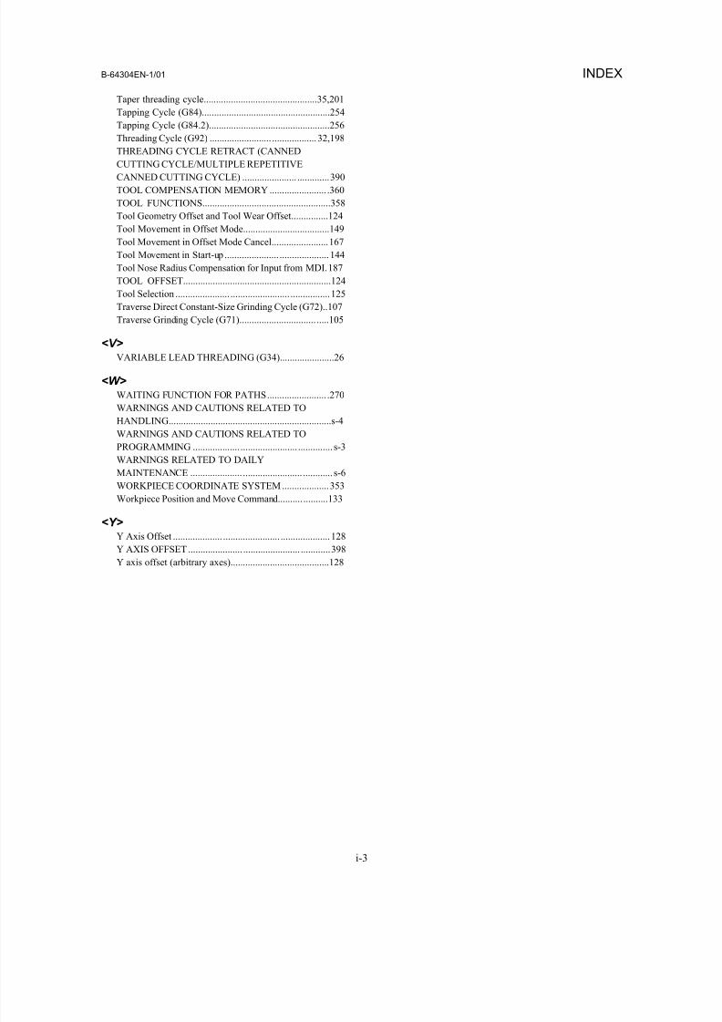
8/16/2019 Manual Operacion para FANUC
http://slidepdf.com/reader/full/manual-operacion-para-fanuc 433/435
B-64304EN-1/01 INDEX
i-3
Taper threading cycle..............................................35,201
Tapping Cycle (G84)....................................................254
Tapping Cycle (G84.2).................................................256
Threading Cycle (G92) ......................... ..................32,198
THREADING CYCLE RETRACT (CANNED
CUTTING CYCLE/MULTIPLE REPETITIVE
CANNED CUTTING CYCLE) ...................... .............390
TOOL COMPENSATION MEMORY ....................... .360
TOOL FUNCTIONS....................................................358
Tool Geometry Offset and Tool Wear Offset...............124
Tool Movement in Offset Mode...................................149
Tool Movement in Offset Mode Cancel.......................167
Tool Movement in Start-up ...................... ....................144
Tool Nose Radius Compensation for Input from MDI.187
TOOL OFFSET............................................................124
Tool Selection ...................... ........................ ................125
Traverse Direct Constant-Size Grinding Cycle (G72)..107
Traverse Grinding Cycle (G71)............................... .....105
<V>
VARIABLE LEAD THREADING (G34)......................26
<W>
WAITING FUNCTION FOR PATHS........................ .270
WARNINGS AND CAUTIONS RELATED TO
HANDLING..................................................................s-4
WARNINGS AND CAUTIONS RELATED TO
PROGRAMMING ................... ....................... .............. s-3
WARNINGS RELATED TO DAILY
MAINTENANCE ..................... ........................ ............ s-6
WORKPIECE COORDINATE SYSTEM...................353
Workpiece Position and Move Command.......... ..........133
<Y>
Y Axis Offset .................... ....................... ....................128
Y AXIS OFFSET ...................... ....................... ............398
Y axis offset (arbitrary axes)........................................128

8/16/2019 Manual Operacion para FANUC
http://slidepdf.com/reader/full/manual-operacion-para-fanuc 434/435
8/16/2019 Manual Operacion para FANUC
http://slidepdf.com/reader/full/manual-operacion-para-fanuc 435/435
R e v i s
i o n R e c o r d
e s 0 i M
a t e - M O D E L D
O P E R A T O R ’ S M A
N U A L ( F o r L a t h e S y s t e m
)
( B - 6 4
3 0 4 E N - 1 )
t e n t s
E d i t i o n
D a t e
C o n t e n t s