itu-t g.664
DESCRIPTION
ITU-T G.664TRANSCRIPT
INTERNATIONAL TELECOMMUNICATION UNION
G.664TELECOMMUNICATION STANDARDIZATION SECTOR OF ITU
(06/99)
SERIES G: TRANSMISSION SYSTEMS AND MEDIA, DIGITAL SYSTEMS AND NETWORKS Transmission media characteristics – Characteristics of optical components and subsystems
Optical safety procedures and requirements for optical transport systems
ITU-T Recommendation G.664 (Previously CCITT Recommendation)
ITU-T G-SERIES RECOMMENDATIONS
TRANSMISSION SYSTEMS AND MEDIA, DIGITAL SYSTEMS AND NETWORKS
For further details, please refer to ITU-T List of Recommendations.
INTERNATIONAL TELEPHONE CONNECTIONS AND CIRCUITS G.100–G.199 INTERNATIONAL ANALOGUE CARRIER SYSTEM GENERAL CHARACTERISTICS COMMON TO ALL ANALOGUE CARRIER-TRANSMISSION SYSTEMS
G.200–G.299
INDIVIDUAL CHARACTERISTICS OF INTERNATIONAL CARRIER TELEPHONE SYSTEMS ON METALLIC LINES
G.300–G.399
GENERAL CHARACTERISTICS OF INTERNATIONAL CARRIER TELEPHONE SYSTEMS ON RADIO-RELAY OR SATELLITE LINKS AND INTERCONNECTION WITH METALLIC LINES
G.400–G.449
COORDINATION OF RADIOTELEPHONY AND LINE TELEPHONY G.450–G.499 TESTING EQUIPMENTS TRANSMISSION MEDIA CHARACTERISTICS
General G.600–G.609 Symmetric cable pairs G.610–G.619 Land coaxial cable pairs G.620–G.629 Submarine cables G.630–G.649 Optical fibre cables G.650–G.659 Characteristics of optical components and subsystems G.660–G.699
DIGITAL TRANSMISSION SYSTEMS TERMINAL EQUIPMENTS G.700–G.799 DIGITAL NETWORKS G.800–G.899 DIGITAL SECTIONS AND DIGITAL LINE SYSTEM G.900–G.999
Recommendation G.664 (06/99) i
ITU-T RECOMMENDATION G.664
OPTICAL SAFETY PROCEDURES AND REQUIREMENTS FOR OPTICAL TRANSPORT SYSTEMS
Summary This Recommendation provides guidelines and requirements for techniques to provide optically safe working conditions (of Hazard Level 3A or lower) on optical interfaces of the Optical Transport Network, including conventional SDH systems, for equipment in restricted and controlled locations. For SDH applications a transverse compatible Automatic Laser Shutdown and Restart procedure is specified. Furthermore a clarification of the IEC 60825 standard on optical safety is provided.
Source
ITU-T Recommendation G.664 was prepared by ITU-T Study Group 15 (1997-2000) and was approved under the WTSC Resolution No. 1 procedure on the 22nd of June 1999.
ii Recommendation G.664 (06/99)
FOREWORD
ITU (International Telecommunication Union) is the United Nations Specialized Agency in the field of telecommunications. The ITU Telecommunication Standardization Sector (ITU-T) is a permanent organ of the ITU. The ITU-T is responsible for studying technical, operating and tariff questions and issuing Recommendations on them with a view to standardizing telecommunications on a worldwide basis.
The World Telecommunication Standardization Conference (WTSC), which meets every four years, establishes the topics for study by the ITU-T Study Groups which, in their turn, produce Recommendations on these topics.
The approval of Recommendations by the Members of the ITU-T is covered by the procedure laid down in WTSC Resolution No. 1.
In some areas of information technology which fall within ITU-T’s purview, the necessary standards are prepared on a collaborative basis with ISO and IEC.
NOTE
In this Recommendation the term recognized operating agency (ROA) includes any individual, company, corporation or governmental organization that operates a public correspondence service. The terms Administration, ROA and public correspondence are defined in the Constitution of the ITU (Geneva, 1992).
INTELLECTUAL PROPERTY RIGHTS
The ITU draws attention to the possibility that the practice or implementation of this Recommendation may involve the use of a claimed Intellectual Property Right. The ITU takes no position concerning the evidence, validity or applicability of claimed Intellectual Property Rights, whether asserted by ITU members or others outside of the Recommendation development process.
As of the date of approval of this Recommendation, the ITU had not received notice of intellectual property, protected by patents, which may be required to implement this Recommendation. However, implementors are cautioned that this may not represent the latest information and are therefore strongly urged to consult the TSB patent database.
� ITU 1999
All rights reserved. No part of this publication may be reproduced or utilized in any form or by any means, electronic or mechanical, including photocopying and microfilm, without permission in writing from the ITU.
Recommendation G.664 (06/99) iii
CONTENTS
Page
1 Scope........................................................................................................................... 1
2 References................................................................................................................... 1
3 Terms and definitions ................................................................................................. 2
3.1 Definitions .................................................................................................................. 2
3.2 Terms defined in other Recommendations ................................................................. 2
4 Abbreviations.............................................................................................................. 2
5 General optical safety considerations ......................................................................... 3
6 Procedures................................................................................................................... 4
6.1 General........................................................................................................................ 4
6.2 Single-channel point-to-point SDH without line amplifiers....................................... 4
6.3 Single-channel point-to-point SDH with line amplifiers ............................................ 9
6.4 Multichannel and OTN applications........................................................................... 10
6.5 Bidirectional applications ........................................................................................... 12

Recommendation G.664 (06/99) 1
Recommendation G.664
OPTICAL SAFETY PROCEDURES AND REQUIREMENTS FOR OPTICAL TRANSPORT SYSTEMS
(Geneva, 1999)
1 Scope This Recommendation provides guidelines and requirements for techniques to provide optically safe working conditions (of Hazard Level 3A or lower) on optical interfaces of the Optical Transport Network, including conventional SDH systems, for equipment in restricted and controlled locations. In order to provide transverse compatibility, i.e. the possibility of mixing various manufacturers' equipments within a single optical section, this Recommendation also defines procedures for Automatic Laser Shutdown (ALS) and Automatic Power Reduction (APR) at optical interfaces where optical safety limits specified by recognized standards are exceeded. Furthermore, a clarification of the alternatively existing term Automatic Power Shutdown (APSD) is given. The definition of optical safety procedures for the Optical Access Network is regarded as being outside the scope of this Recommendation.
Main fields of application are conventional SDH line systems (without optical amplifiers) as specified in Recommendation G.957, SDH line systems with optical amplifiers and systems designed for the Optical Transport Network.
The impact of bidirectional transmission as described in Recommendation G.692 has also been considered.
Because of desired backwards compatibility with no longer existing Recommendations on the subject of optical safety, this Recommendation provides (besides requirements) some options for safety procedures in case of single- and multichannel SDH systems with line amplifiers.
2 References The following ITU-T Recommendations and other references contain provisions, which through reference in this text constitute provisions of this Recommendation. At the time of publication, the editions indicated were valid. All Recommendations and other references are subject to revision; all users of this Recommendation are therefore encouraged to investigate the possibility of applying the most recent edition of the Recommendations and other references listed below. A list of the currently valid ITU-T Recommendations is regularly published.
– ITU-T Recommendation G.662 (1998), Generic characteristics of optical fibre amplifier devices and subsystems.
– ITU-T Recommendation G.692 (1998), Optical interfaces for multichannel systems with optical amplifiers.
– ITU-T Recommendation G.783 (1997), Characteristics of synchronous digital hierarchy (SDH) equipment functional blocks.
– ITU-T Recommendation G.872 (1999), Architecture of optical transport networks.
– ITU-T Recommendation G.957 (1995), Optical interfaces for equipments and systems relating to the synchronous digital hierarchy.
2 Recommendation G.664 (06/99)
– IEC 60825-1 (1998), Safety of laser products. Part 1: Equipment classification, requirements and user's guide.
– IEC 60825-2 (1993), Safety of laser products. Part 2: Safety of optical fibre communication systems plus Amendment 1 (1997).
3 Terms and definitions
3.1 Definitions This Recommendation defines the following terms:
3.1.1 automatic laser shutdown (ALS): A technique (procedure) to automatically shutdown the output power of laser transmitters and optical amplifiers to avoid exposure to hazardous levels.
3.1.2 automatic power reduction (APR): A technique (procedure) to automatically reduce the output power of optical amplifiers to avoid exposure to hazardous levels.
3.1.3 automatic power shutdown (APSD): A technique (procedure) to automatically shutdown the output power of optical amplifiers to avoid exposure to hazardous levels; within the context of this recommendation the term APSD is equivalent to the term ALS.
3.1.4 main (optical) path: The fibre plant between the S or S' point of the transmitter equipment and the R or R' point of the receiver equipment.
3.1.5 main path interfaces: The interfaces to the fibre plant.
3.2 Terms defined in other Recommendations This Recommendation uses the following terms defined within other ITU-T Recommendations:
Loss of Signal (LOS) Recommendation G.783
Optical Multiplex Section (OMS) Recommendation G.872
Optical Supervisory Channel (OSC) Recommendation G.692
Optical Transmission Section (OTS) Recommendation G.872
4 Abbreviations This Recommendation uses the following abbreviations:
ALS Automatic Laser Shutdown
APR Automatic Power Reduction
APSD Automatic Power Shutdown
BA Booster Amplifier
dLOS Loss of Signal defect
LA Line Amplifier
LOC-OTS Loss of Continuity on Optical Transmission Section
LOS Loss of Signal
MPI Main Path Interface
MPI-R Receive Main Path Interface reference point
Recommendation G.664 (06/99) 3
MPI-S Source Main Path Interface reference point
OAR Optically Amplified Receiver
OAT Optically Amplified Transmitter
OMS Optical Multiplex Section
OSC Optical Supervisory Channel
OTN Optical Transport Network
OTS Optical Transmission Section
PA Pre-Amplifier
SDH Synchronous Digital Hierarchy
WDM Wavelength Division Multiplexing
5 General optical safety considerations In this clause the difference between "Laser Class", defined in IEC 60825-1, and "Laser Hazard Level", defined in IEC 60825-2, is further clarified.
Class: The word "Class" refers to a scheme by which, based on emission levels, a product or internal emitter can be grouped with respect to its safety. These levels are described in Accessible Emission Limit Tables in IEC 60825 Part 1. Classes range from Class 1, which is safe under reasonably foreseeable conditions, to Class 4 which is potentially the most hazardous case. For IEC 60825 Part 1, classification of products are based on normal operating conditions.
Hazard Level: "Hazard Level" is a term from IEC 60825 Part 2 and refers to the potential hazard from laser emissions at any location in an end-to-end fibre optic communication system that may be accessible during service or in the event of a failure or fibre disconnection. The assessment of the hazard level uses the Class Accessible Emission Limit tables described in the IEC 60825 Part 1 standard.
Annex A of IEC 60825 Part 2 gives the following additional clarification: "a whole optical fibre communication system will not be classified in the same way as required by IEC 60825-1. This is because, under intended operation, the optical radiation is totally enclosed, and it can be argued that a rigorous interpretation of IEC 60825-1 would give a Class 1 allocation to all systems, which may not reflect accurately the potential hazard".
Based upon this statement, a complete system can be regarded as a Class 1 laser product because, under normal conditions, the emissions are completely enclosed (like a laser printer) and no light should be emitting outside the enclosure. It is not until the fibre breaks, or an optical connector is unplugged, that someone might be exposed to a potentially hazardous light level if the internal emitters are of high enough power.
Therefore, for each optical output port the Hazard Level must be assessed. The Hazard Level limits depend on the "dominant" wavelength range, taking into consideration that IEC 60825-1 defines different limits for different wavelength ranges. Details can be found in IEC 60825-1. Furthermore, IEC 60825-2 allows the use of Automatic Power Reduction (APR) techniques to achieve a lower (less hazardous) Hazard Level based on the operational power in the fibre and speed of automatic power reduction. In this Recommendation, Automatic Laser Shutdown (ALS) techniques (in case of SDH systems) which have the same purpose, i.e. to provide safe working environments, are also described.
4 Recommendation G.664 (06/99)
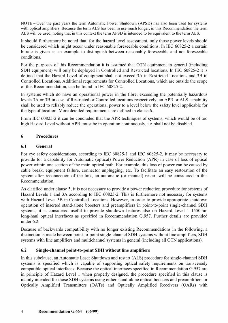
NOTE – Over the past years the term Automatic Power Shutdown (APSD) has also been used for systems with optical amplifiers. Because the term ALS has been in use much longer, in this Recommendation the term ALS will be used, noting that in this context the term APSD is intended to be equivalent to the term ALS.
It should furthermore be noted that, for the hazard level assessment, only those power levels should be considered which might occur under reasonable foreseeable conditions. In IEC 60825-2 a certain bitrate is given as an example to distinguish between reasonably foreseeable and not foreseeable conditions.
For the purposes of this Recommendation it is assumed that OTN equipment in general (including SDH equipment) will only be deployed in Controlled and Restricted locations. In IEC 60825-2 it is defined that the Hazard Level of equipment shall not exceed 3A in Restricted Locations and 3B in Controlled Locations. Additional requirements for Controlled Locations, which are outside the scope of this Recommendation, can be found in IEC 60825-2.
In systems which do have an operational power in the fibre, exceeding the potentially hazardous levels 3A or 3B in case of Restricted or Controlled locations respectively, an APR or ALS capability shall be used to reliably reduce the operational power to a level below the safety level applicable for the type of location. More detailed requirements are defined in clause 6.
From IEC 60825-2 it can be concluded that the APR techniques of systems, which would be of too high Hazard Level without APR, must be in operation continuously, i.e. shall not be disabled.
6 Procedures
6.1 General For eye safety considerations, according to IEC 60825-1 and IEC 60825-2, it may be necessary to provide for a capability for Automatic (optical) Power Reduction (APR) in case of loss of optical power within one section of the main optical path. For example, this loss of power can be caused by cable break, equipment failure, connector unplugging, etc. To facilitate an easy restoration of the system after reconnection of the link, an automatic (or manual) restart will be considered in this Recommendation.
As clarified under clause 5, it is not necessary to provide a power reduction procedure for systems of Hazard Levels 1 and 3A according to IEC 60825-2. This is furthermore not necessary for systems with Hazard Level 3B in Controlled Locations. However, in order to provide appropriate shutdown operation of inserted stand-alone boosters and preamplifiers in point-to-point single-channel SDH systems, it is considered useful to provide shutdown features also on Hazard Level 1 1550 nm long-haul optical interfaces as specified in Recommendation G.957. Further details are provided under 6.2.
Because of backwards compatibility with no longer existing Recommendations in the following, a distinction is made between point-to-point single-channel SDH systems without line amplifiers, SDH systems with line amplifiers and multichannel systems in general (including all OTN applications).
6.2 Single-channel point-to-point SDH without line amplifiers In this subclause, an Automatic Laser Shutdown and restart (ALS) procedure for single-channel SDH systems is specified which is capable of supporting optical safety requirements on transversely compatible optical interfaces. Because the optical interfaces specified in Recommendation G.957 are in principle of Hazard Level 1 when properly designed, the procedure specified in this clause is mainly intended for those SDH systems using either stand-alone optical boosters and preamplifiers or Optically Amplified Transmitters (OATs) and Optically Amplified Receivers (OARs) with
Recommendation G.664 (06/99) 5
operational output power of Hazard Level 3B in restricted Locations. Accommodation of this procedure, in the case of the additional presence of optical line amplifiers, is described under 6.3. NOTE 1 – The ALS procedure specified in this subclause, in particular the associated time constants, is designed to operate correctly only if no additional equipment is present between MPI-S and MPI-R (see Figure 2).
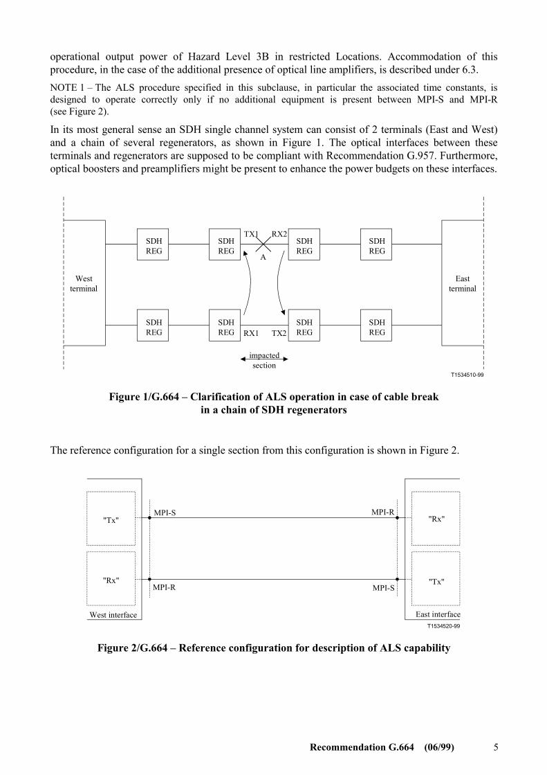
In its most general sense an SDH single channel system can consist of 2 terminals (East and West) and a chain of several regenerators, as shown in Figure 1. The optical interfaces between these terminals and regenerators are supposed to be compliant with Recommendation G.957. Furthermore, optical boosters and preamplifiers might be present to enhance the power budgets on these interfaces.
T1534510-99
TX1 RX2
TX2RX1
A
West terminal
East terminal
impactedsection
SDHREG
SDHREG
SDHREG
SDHREG
SDHREG
SDHREG
SDHREG
SDHREG
Figure 1/G.664 – Clarification of ALS operation in case of cable break in a chain of SDH regenerators
The reference configuration for a single section from this configuration is shown in Figure 2.
T1534520-99
MPI-S
MPI-SMPI-R
MPI-R"Tx"
"Tx""Rx"
"Rx"
West interface East interface
Figure 2/G.664 – Reference configuration for description of ALS capability
6 Recommendation G.664 (06/99)
In Figure 2, "Tx" can be either a transmitter according to Recommendation G.957 (specified at reference point S) or it may include optical amplification to increase the output power (i.e. OAT or BA in combination with suitable adaptation of equipment according to Recommendation G.957). Furthermore, "Rx" can be either a receiver according to Recommendation G.957 (specified at reference point R) or it may include optical preamplification (i.e. OAR or PA used in combination with a suitable adaptation of equipment according to Recommendation G.957). The "West" and "East" Interfaces may be part of terminal equipment or of electrical regenerators.
In case a cable break happens at point A of Figure 1, the consecutive Loss of Signal defect (dLOS) at "conventional" receiver RX2 is used to shutdown the output of "conventional" transmitter TX2 which is the adjacent transmitter in the opposite direction. This in turn leads to dLOS in "conventional" receiver RX1 which in its turn shuts down "conventional" transmitter TX1. After shutdown the output power of the transmitter shall be sufficiently low to generate dLOS at the receiver side. The definition of LOS is given in Recommendation G.783. In all cases only the impacted section may be shutdown, which is clarified in Figure 1.
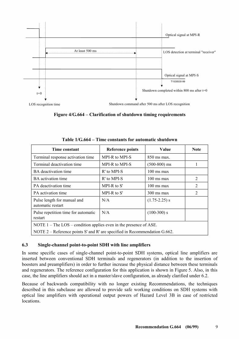
After at least 500 ms of continuous presence of the LOS defect, the actual shutdown command will be activated, which shall result in reduction of the optical output power at MPI-S within 800 ms from the moment loss of optical signal occurs at MPI-R. NOTE 2 – The complete shutdown of the "conventional" transmitters is not required by IEC 60825-2, but is necessary in this case, because otherwise LOS might not be detected in the "conventional" receiver. The remaining output power of the involved optical amplifiers after shutdown of the "conventional" transmitters shall be within Hazard Level 3A for equipment in restricted locations, noting that this does not exclude reduction to within Hazard Level 1 (including the possibility of complete shutdown).
It is assumed that the optical boosters operate in a master/slave configuration, i.e. when the input signal vanishes, the output should be shut down, and when the input signal returns, the output power should be restored. It will not be necessary to shutdown the output of the preamplifier in case it is within Hazard Level 1 or 3A under reasonable foreseeable conditions as clarified under clause 5.
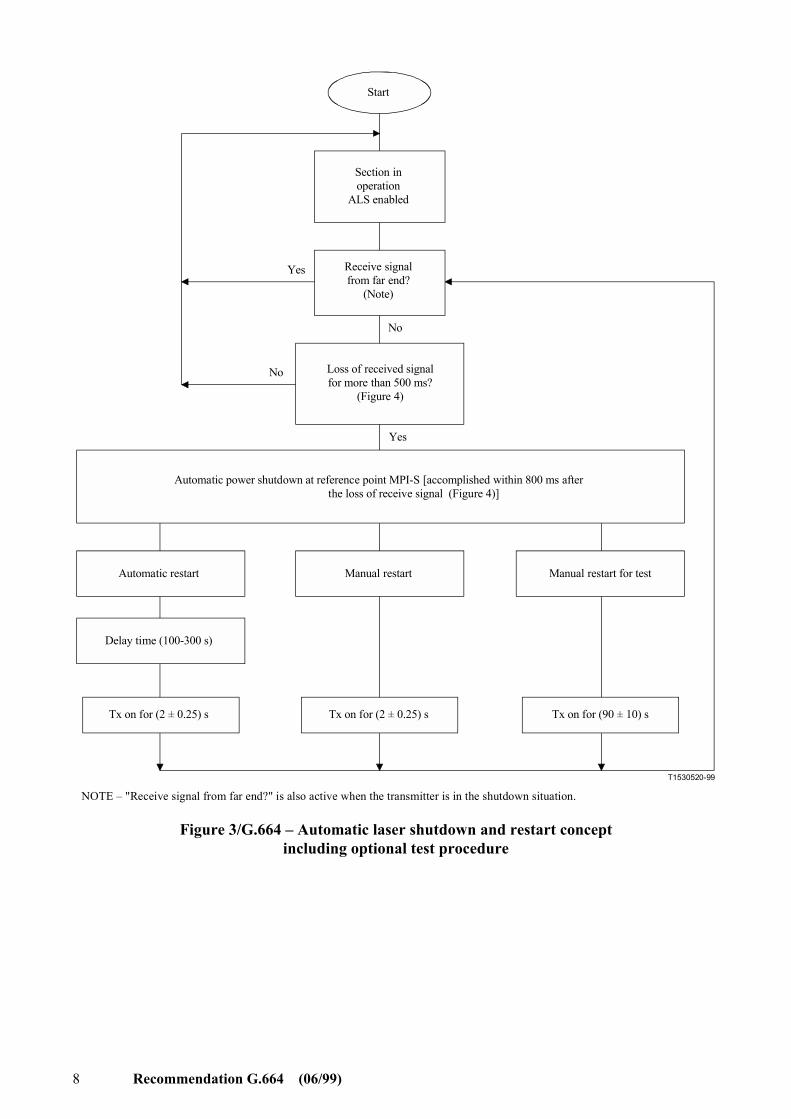
Figure 3 shows a conceptual diagram of the automatic laser shutdown and restart procedure, for which it should be noted that this figure is not intended to be a state diagram. A clarification of the associated shutdown timing requirements is shown in Figure 4. NOTE 3 – If automatic laser shutdown is implemented, it should not impair fault sectionalization capability in case of loss of signal at the transmitter or the receiver due to causes other than a cable break.
When the connection in the cable has been repaired, either an automatic or a manual restart according to Figure 3, at TX1 or TX2, is necessary to restore transmission. The principle for the restart of a shutdown system is the use of a restart pulse, which shall be within Hazard Level 3A (not excluding Hazard Level 1) to minimize risk of exposure to hazardous power levels. NOTE 4 – It is not implied by this text that both an automatic and a manual restart be implemented simultaneously.
NOTE 5 – In Figure 3 the minimum delay between the restart pulses is specified to be 100 s, but in order to have backwards compatibility with no longer existing Recommendations, a minimum delay of 60 s can be used, if the optical power within the restart pulse is 3 dB lower than allowed for the 100 s minimum delay time. IEC 60825 requires that within a 100 s period the total energy of all pulses has to be accounted for to calculate the Hazard Level.
Recommendation G.664 (06/99) 7
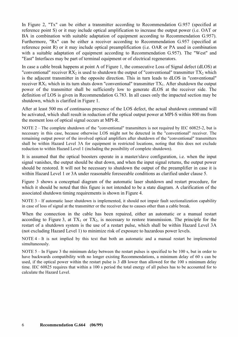
The activation response time of the "transmitter"/"receiver" combination (as shown in Figure 1), measured from "receiver" input (point MPI-R) to transmitter output (point MPI-S) should be less than 0.85 s. This response time of 0.85 s refers to the time difference between the moment light enters the "receiver" at point MPI-R and the moment the "transmitter" starts light emitting at point MPI-S in case the "transmitter" is in the shutdown situation. The optical amplifiers shall restart sufficiently slow (within the above-mentioned activation response time) to avoid, as much as possible, optical surges.
The maximum deactivation time of booster and preamplifiers shall be 100 ms. A booster and preamplifier shall have a maximum activation time of 100 ms and 300 ms respectively.
The various time constants are summarized in Table 1.
For test and monitoring purposes it is possible to override the shutdown mechanism by switching on the laser manually. NOTE 6 – During "manual restart for test" specific care must be taken to assure connectivity to avoid exposure to Hazardous optical levels, particularly in case of Hazard Level 3B for equipment in restricted locations. Furthermore, to avoid accidental overexposure, it is recommended to use a sufficient delay, e.g. 100 s, between individual manual restart pulses.
"Manual restart" or "Manual restart for test" can only be activated when the laser is shut down.
In case protection switching in the electrical domain (e.g. MSP or MSSPRING) is implemented, a working channel receiver should shut down a working channel transmitter. Similarly, a protection channel receiver should shut down a protection channel transmitter.
8 Recommendation G.664 (06/99)
T1530520-99
Tx on for (2 ± 0.25) s
Automatic restart Manual restart Manual restart for test
Delay time (100-300 s)
No
Yes
No
Yes
Start
Tx on for (2 ± 0.25) s Tx on for (90 ± 10) s
Section inoperation
ALS enabled
Receive signalfrom far end?
(Note)
Automatic power shutdown at reference point MPI-S [accomplished within 800 ms after the loss of receive signal (Figure 4)]
Loss of received signalfor more than 500 ms?
(Figure 4)
NOTE – "Receive signal from far end?" is also active when the transmitter is in the shutdown situation.
Figure 3/G.664 – Automatic laser shutdown and restart concept including optional test procedure
Recommendation G.664 (06/99) 9
T1530530-99
t=0
At least 500 ms
LOS recognition time Shutdown command after 500 ms after LOS recognition
Shutdown completed within 800 ms after t=0
Optical signal at MPI-S
LOS detection at terminal "receiver"
Optical signal at MPI-R
Figure 4/G.664 – Clarification of shutdown timing requirements
Table 1/G.664 – Time constants for automatic shutdown
Time constant Reference points Value Note
Terminal response activation time MPI-R to MPI-S 850 ms max. Terminal deactivation time MPI-R to MPI-S (500-800) ms 1 BA deactivation time R' to MPI-S 100 ms max BA activation time R' to MPI-S 100 ms max 2 PA deactivation time MPI-R to S' 100 ms max 2 PA activation time MPI-R to S' 300 ms max 2 Pulse length for manual and automatic restart
N/A (1.75-2.25) s
Pulse repetition time for automatic restart
N/A (100-300) s
NOTE 1 – The LOS – condition applies even in the presence of ASE. NOTE 2 – Reference points S' and R' are specified in Recommendation G.662.
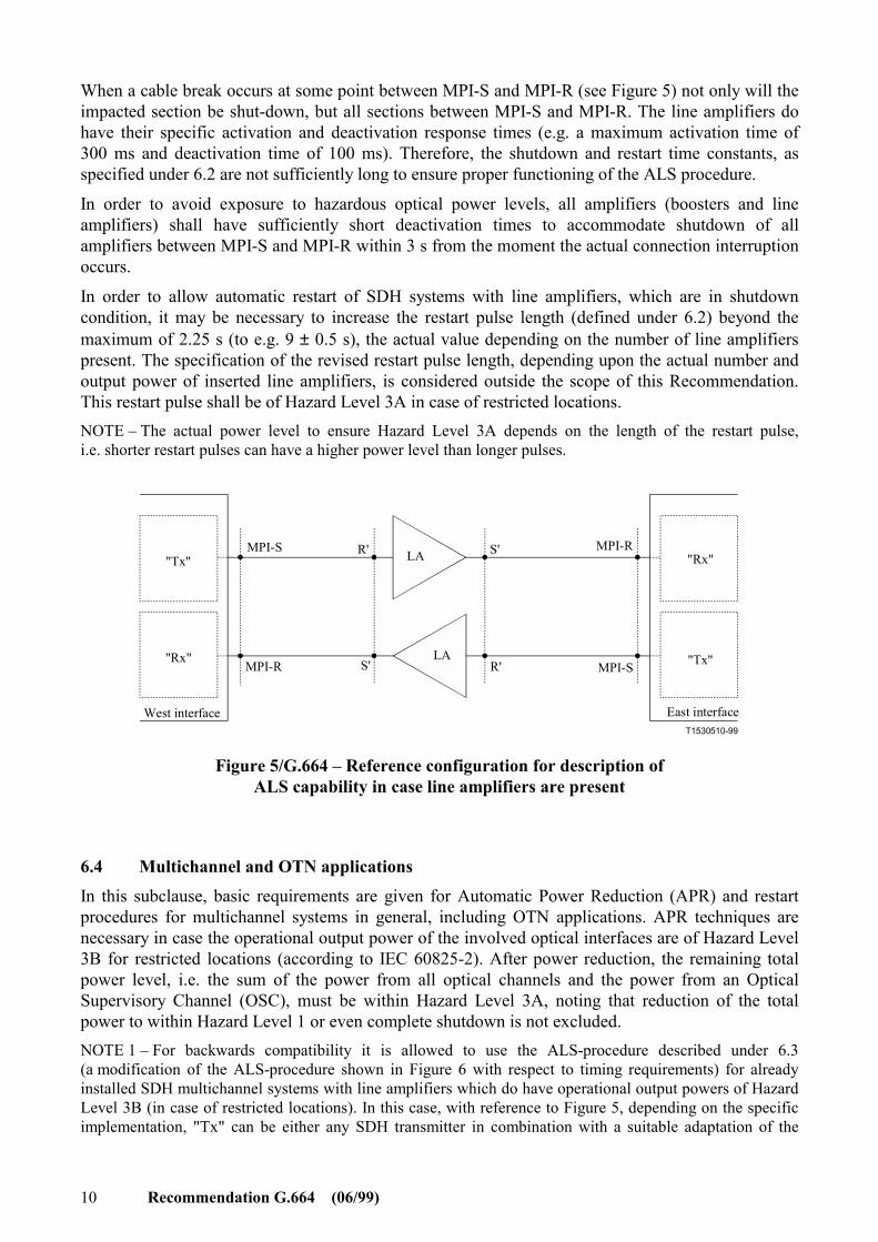
6.3 Single-channel point-to-point SDH with line amplifiers In some specific cases of single-channel point-to-point SDH systems, optical line amplifiers are inserted between conventional SDH terminals and regenerators (in addition to the insertion of boosters and preamplifiers) in order to further increase the physical distance between these terminals and regenerators. The reference configuration for this application is shown in Figure 5. Also, in this case, the line amplifiers should act in a master/slave configuration, as already clarified under 6.2.
Because of backwards compatibility with no longer existing Recommendations, the techniques described in this subclause are allowed to provide safe working conditions on SDH systems with optical line amplifiers with operational output powers of Hazard Level 3B in case of restricted locations.
10 Recommendation G.664 (06/99)
When a cable break occurs at some point between MPI-S and MPI-R (see Figure 5) not only will the impacted section be shut-down, but all sections between MPI-S and MPI-R. The line amplifiers do have their specific activation and deactivation response times (e.g. a maximum activation time of 300 ms and deactivation time of 100 ms). Therefore, the shutdown and restart time constants, as specified under 6.2 are not sufficiently long to ensure proper functioning of the ALS procedure.
In order to avoid exposure to hazardous optical power levels, all amplifiers (boosters and line amplifiers) shall have sufficiently short deactivation times to accommodate shutdown of all amplifiers between MPI-S and MPI-R within 3 s from the moment the actual connection interruption occurs.
In order to allow automatic restart of SDH systems with line amplifiers, which are in shutdown condition, it may be necessary to increase the restart pulse length (defined under 6.2) beyond the maximum of 2.25 s (to e.g. 9 ± 0.5 s), the actual value depending on the number of line amplifiers present. The specification of the revised restart pulse length, depending upon the actual number and output power of inserted line amplifiers, is considered outside the scope of this Recommendation. This restart pulse shall be of Hazard Level 3A in case of restricted locations. NOTE – The actual power level to ensure Hazard Level 3A depends on the length of the restart pulse, i.e. shorter restart pulses can have a higher power level than longer pulses.
T1530510-99
"Tx"
"Tx""Rx"
"Rx"
West interface East interface
MPI-S
MPI-SMPI-R
MPI-RR'
R'S'
S'LA
LA
Figure 5/G.664 – Reference configuration for description of ALS capability in case line amplifiers are present
6.4 Multichannel and OTN applications In this subclause, basic requirements are given for Automatic Power Reduction (APR) and restart procedures for multichannel systems in general, including OTN applications. APR techniques are necessary in case the operational output power of the involved optical interfaces are of Hazard Level 3B for restricted locations (according to IEC 60825-2). After power reduction, the remaining total power level, i.e. the sum of the power from all optical channels and the power from an Optical Supervisory Channel (OSC), must be within Hazard Level 3A, noting that reduction of the total power to within Hazard Level 1 or even complete shutdown is not excluded. NOTE 1 – For backwards compatibility it is allowed to use the ALS-procedure described under 6.3 (a modification of the ALS-procedure shown in Figure 6 with respect to timing requirements) for already installed SDH multichannel systems with line amplifiers which do have operational output powers of Hazard Level 3B (in case of restricted locations). In this case, with reference to Figure 5, depending on the specific implementation, "Tx" can be either any SDH transmitter in combination with a suitable adaptation of the
Recommendation G.664 (06/99) 11
MUX/OA equipment or the MUX/OA equipment. Furthermore "Rx" can be either the corresponding SDH receiver in combination with a suitable adaptation of the OA/DEMUX equipment or the OA/DEMUX equipment.
T1530540-99
West Multiplex
East Multiplex
T1 R2
T2R1
A
OTS
OMS
LA LA
LA LA LA LA
LA LA
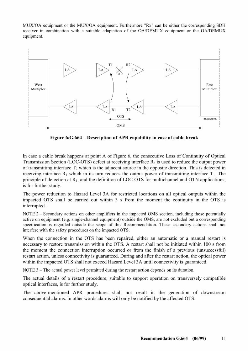
Figure 6/G.664 – Description of APR capability in case of cable break
In case a cable break happens at point A of Figure 6, the consecutive Loss of Continuity of Optical Transmission Section (LOC-OTS) defect at receiving interface R2 is used to reduce the output power of transmitting interface T2 which is the adjacent source in the opposite direction. This is detected in receiving interface R1 which in its turn reduces the output power of transmitting interface T1. The principle of detection at R1, and the definition of LOC-OTS for multichannel and OTN applications, is for further study.
The power reduction to Hazard Level 3A for restricted locations on all optical outputs within the impacted OTS shall be carried out within 3 s from the moment the continuity in the OTS is interrupted. NOTE 2 – Secondary actions on other amplifiers in the impacted OMS section, including those potentially active on equipment (e.g. single-channel equipment) outside the OMS, are not excluded but a corresponding specification is regarded outside the scope of this Recommendation. These secondary actions shall not interfere with the safety procedures on the impacted OTS.
When the connection in the OTS has been repaired, either an automatic or a manual restart is necessary to restore transmission within the OTS. A restart shall not be initiated within 100 s from the moment the connection interruption occurred or from the finish of a previous (unsuccessful) restart action, unless connectivity is guaranteed. During and after the restart action, the optical power within the impacted OTS shall not exceed Hazard Level 3A until connectivity is guaranteed. NOTE 3 – The actual power level permitted during the restart action depends on its duration.
The actual details of a restart procedure, suitable to support operation on transversely compatible optical interfaces, is for further study.
The above-mentioned APR procedures shall not result in the generation of downstream consequential alarms. In other words alarms will only be notified by the affected OTS.

12 Recommendation G.664 (06/99)
6.5 Bidirectional applications Bidirectional systems have to meet the same optical safety requirements and will use the same principles as unidirectional systems. The precise specification of these procedures are for further study.

ITU-T RECOMMENDATIONS SERIES
Series A Organization of the work of the ITU-T
Series B Means of expression: definitions, symbols, classification
Series C General telecommunication statistics
Series D General tariff principles
Series E Overall network operation, telephone service, service operation and human factors
Series F Non-telephone telecommunication services
Series G Transmission systems and media, digital systems and networks
Series H Audiovisual and multimedia systems
Series I Integrated services digital network
Series J Transmission of television, sound programme and other multimedia signals
Series K Protection against interference
Series L Construction, installation and protection of cables and other elements of outside plant
Series M TMN and network maintenance: international transmission systems, telephone circuits, telegraphy, facsimile and leased circuits
Series N Maintenance: international sound programme and television transmission circuits
Series O Specifications of measuring equipment
Series P Telephone transmission quality, telephone installations, local line networks
Series Q Switching and signalling
Series R Telegraph transmission
Series S Telegraph services terminal equipment
Series T Terminals for telematic services
Series U Telegraph switching
Series V Data communication over the telephone network
Series X Data networks and open system communications
Series Y Global information infrastructure and Internet protocol aspects
Series Z Languages and general software aspects for telecommunication systems