design of diagnostic examination room using...
TRANSCRIPT

DESIGN OF DIAGNOSTIC EXAMINATION ROOM USING MCNPX
SIMULATION
Oleh:
ARDIAN FEBRIANTY PADJI MAMO
NIM : 642012019
TUGAS AKHIR
Diajukan kepada Program Studi Pendidikan Fisika, Fakultas Sains dan Matematika guna
memenuhi sebagian dari persyaratan untuk memperoleh gelar Sarjana Sains
Program Studi Fisika
PROGRAM STUDI PENDIDIKAN FISIKA
FAKULTAS SAINS DAN MATEMATIKA
UNIVERSITAS KRISTEN SATYA WACANA
SALATIGA
2017

ii

iii

iv
MOTTO Mazmur 126:5-6 “Orang-orang yang menabur dengan
mencucurkan air mata, akan menuai dengan bersorak-sorai .
Orang yang berjalan maju dengan menangis sambil menabur
benih, pasti pulang dengan sorak-sorai sambil membawa berkas-
berkasnya.
Yeremia 17:7 “Diberkatilah orang yang mengandalkan TUHAN,
yang menaruh harapannya pada TUHAN!
v
KATA PENGANTAR
Puji Syukur kehadirat Tuhan Yang Maha Esa yang telah melimpahkan rahmat, karunia dan
kasih-Nya sehingga penulis dapat menyelesaikan Tugas Akhir dengan judul “Design Of
Diagnostic X-Ray Examination Room Using MCNPX Simulation”
Tugas Akhir ini diajukan untuk memenuhi sebagian persyaratan guna mencapai gelar Sarjana
Sains dari Jurusan Fisika, Fakultas Sains dan Matematika (FSM), Universitas Kristen Satya
Wacana. Dalam pelaksanaan dan penyusunan laporan ini, penulis tidak lepas dari bimbingan,
pengarahan dan bantuan dari berbagai pihat yang selalu mendukung, memberikan masukan dan
saran yang berguna sehingga dapat terlaksana dengan baik. Atas segala bantuan dan dukungan
tersebut, pada kesempatan ini penulis mengucapkan terima kasih kepada :
1. Tuhan Yesus Kristus atas berkat dan perlindungan, tuntunan dan berkatnya, penulis dapat
menyelesaikan tugas akhir ini dengan baik.
2. Orang tua (Bapa Johnny) yang selalu memberikan semangat, materi dan selalu mendoakan
sehingga penulis dapat menyelesaikan penelitian ini dengan baik adanya.
3. Dr. Suryasatriya Trihandaru, S.Si., M.Sc. Nat dan Giner Maslebu S.Pd., S.Si., M.Si. Selaku
dosen pembimbing yang selalu memberikan pengarahan, motivasi dan dukungan.
4. Dr. Suryasatriya Trihandaru, S.Si., M.Sc. Nat selaku Dekan FSM, Diane Noviandini selaku
Kaprogdi dan Nur Aji Wibowo selaku wali studi, Universitas Kristen Satya Wacana.
5. Seluruh Dosen Fisika dan Pendidikan Fisika yang banya memberikan ilmu yang
bermanfaat dan semoga dapat berguna bagi proses kedepannya. Staff dan laboran Fisika
yang telah banyak membantu dalam memfasilitasi sarana dan prasarana untuk proses
pembelajaran.
6. Alm Opa Tana yang selalu bahkan sangat mendukung selama menempuh dunia
pendidikan, yang sangat berdedikasi dalam hidup penulis. Penulis sangat mengucapkan
limpah terima kasih atas dukungan doa, material dan motivasi selama beliau hidup.
7. Saudara-saudaraku tercinta (Kak Dial, kak Dita dan Tini Ucil) yang selalu memberikan
semangat dan dukungan selama kuliah.
8. Penulis mengucapkan terima kasih kepada kak Riando Putra Sabanari (Rian Nyor) atas
doa, dukungan, semangat, serta bantuan materi (Mama Cherly dan P’Oy Sabanari) yang
senantiasa mendukung penulis sampai akhir kuliah ini.
9. Rekan-rekan Fisika 2012 terima kasih untuk kebersamaan yang telah kita bangun selama
kurang lebih 4 tahun ini. Kita adalah keluarga dan selamanya akan menjadi keluarga.
10. Sahabat-sahabat terbaik (Estry, Ramadhan, Jayantry) yang selalu membantu dalam kuliah
dan diluar itupun kalian sangat berharga “you’re the best friends”.
11. Cewe-cewe monsa yang selalu memberikan motivasi serta dukungan kepada penulis untuk
menyelesaikan penulisan tugas akhir (Kak Nolin,Ivone, Dewi, Nanda, Kak Brenda dan
Sarlin) serta anak-anak kost bayangan.
vi

Penulis menyadari bahwa dalam penyusunan laporan Tugas Akhir ini msih banyak
kekurangan, oleh karenannya penulis mengharapkan kritik dan saran yang membangun bagi
perbaikan dan kemajuan penulis. Penulis berharap kiranya melalui penulisan laporan ini dapat
bermanfaat dan memberikan tambahan ilmu bagi pembaca. Sekian dan terima kasih.
Salatiga, 22 Juni 2017
Ardian F. Padji Mamo
vii

DAFTAR ISI
HALAMAN JUDUL ………………………………………………………………………………… i
LEMBAR PENGESAHAN ………………………………………………………………………… ii
PERNYATAAN TIDAK PLAGIAT ……………………………………………………………… iii
PERNYATAAN PERSETUJUAN AKSES …………………………………………………….. iv
MOTTO ………………………………………………………………………………………………… v
KATA PENGANTAR ……………………………………………………………………………….. vi
DAFTAR ISI …………………………………………………………………………………………… viii
ABSTRAK ……………………………………………………………………………………………… ix
I. INTRODUCTION ………………………………………………………………………….. 1
II. METHODS …………………………………………………………………………………… 4
III. RESULT ……………………………………………………………………………………….. 5
IV. DISCUSSION ……………………………………………………………………………….. 7
V. CONCLUTION ………………………………………………………………………………. 9
VI. REFERENCES ………………………………………………………………………………… 9
LAMPIRAN ……………………………………………………………………………………………… 11
viii
DESIGN OF DIAGNOSTIC X-RAY EXAMINATION ROOM WITH
SIMULATION MCNP
Ardian F. Padji Mamo1, Suryasatrya Trihandaru1*, Giner Maslebu1** and Yohannes Sardjono2** 1Department of Physics and Physics Education, Faculty of Science and Mathematics, Universitas Kristen Satya Wacana,
Salatiga Central Java, Indonesia
2Science and Accelerator Technology Centre, National Nuclear Energy Agency, Yogyakarta, Indonesia
*Corresponding author email: [email protected]
**Another corresponding email: [email protected] and [email protected]
Abstrak
Desain Konseptual sebuah perisai radiasi merupakan salah satu parameter yang harus dipenuhi dalam
mendesain ruang pemeriksaan, peralatan keperluan diagnostik, termasuk pada ruang pemeriksaan yang
menggunakan sumber radiasi pengion pesawat sinar-x. Dalam pemanfaatannya harus memperhitungkan
aspek keselamatan kerja radiasi yang dapat menjamin keamanan dan keselamatan kerja radiasi bagi
pekerja dan masyarakat sekitar. Pada penelitian ini akan dimodelkan simulasi ruang pemeriksaan pesawat
sinar-x yang aman sesuai dengan standar Badan Pengawas Tenaga Nuklir (BAPETEN), dan
mensimulasikan desain ruang pemeriksaan sinar-x yang ada disalah satu rumah sakit didaerah Salatiga,
menggunakan software analisis berbasis Monte Carlo (MCNPX) dengan membandingkan perhitungan
tebal penahan radiasi secara teoritis terhadap tebal penahan di Unit Radiologi dengan material perisai
beton. Maka untuk operasional pesawat sinar-x di Unit Radiologi berdasarkan survei dilapangan dan hasil
outpun MCNPX menunjukkan bahwa persyaratan sistem keselamatan kerja radiasi dalam batas aman.
Hasil pengukuran laju paparan radiasi yang dihasilkan pesawat sinar-x pada faktor penyinaran maksimum
energi foton 100 KeV dengan kuat arus 650 mA dan tegangan 150 kV menghasilkan energy foton 4,0625 x
1016 per detik. Dosis yang diterima diluar ruang penyinaran adalah 0,00 mR/jam, yang artinya masih
dibawah nilai batas dosis (NBD) ditentukan 5000 mrem/jam.
Kata Kunci : Penahan radiasi, Sinar-x, MCNPX, Dosis Radiasi, NBD.
Abstract
Conceptual design of a radiation shield is one of the parameters that must be met in the design of the
examination room, equipment for diagnostic purposes, including on examination rooms that use the x-ray
ionizing radiation source. In its use should pay attention to aspects of radiation safety that can ensure the
safety and security of radiation for workers and surrounding communities. This research will be modeled
the simulation of safe x-ray examination room in accordance with the standards of Nuclear Power
Supervisory Agency, and simulate design of x-ray examination room of one hospitals in Salatiga area, using
Monte Carlo based analysis software (MCNPX) by comparing the theoretical radiation retention bending
calculations to the retaining thickness with concrete shielding material. So for operational x-ray in the
Radiology unit based on field survey results and MCNPX output indicates that the requirements of the
radiation safety system are within safe limits. The result of radiation exposure measurements produced by
x-ray on maximum radiation factor of 100 KeV photon energy with a current strength of 650 mA and a
ix

voltage of 150 kV produces photon energy 4,0625 x 10¹⁶ per second. The dose received outside the radiation
chamber is 0.00 mR / hour, which means it is still below the dose limit value (NBD) is determined 5000
mrem / hour. The dose received outside the radiation space is 0.00 mR / hour, which means it is still below
the limit value Dose (NBD) determined 5000 mrem / hour.
Keywords: Radiation Shield, X-ray, MCNPX, Radiation Dose, Dose Limit Value
x
2
1. Introduction
Protection against medical exposure is a key issue when applying compliance test obligations
to x-ray devices for diagnostic radiology and interventions. National Nuclear Energy Supervisory
Agency (BAPETEN) is currently actively providing guidance regarding the use and permit holder in the
protection of radiation hazard (Rusmanto, 2014). In Government Regulation no. 33 of 2007 concerning
the Safety of Radioactive Radiation and Ignition of Radioactive Sources Article 41-43 states that Article
41 (1) Technical requirements as referred to in Article 4 paragraph (3) letter c shall be fulfilled for each
Utilization of Nuclear Power in accordance with the magnitude of potential hazard Source used , (2)
Technical requirements as referred to in paragraph (1) shall include: a. Layered defense system; and b.
Proven engineering practices. Article 42 (1) The layered defense system as referred to in Article 41
paragraph (2) letter a shall be applied in the design of safety systems. (2) Provisions on layered defense
systems for each type of Sources used in the Utilization of Nuclear Power shall be governed by a
BAPETEN Regulation Head. Article 43 (1) The proven engineering practice as intended in Article 41
paragraph (2) letter b shall be applied to the Source in accordance with its potential danger. (2) License
Holder, in the application of proven engineering practice as intended in paragraph (1), shall: a. Taking
into account other documented requirements, standards and other documented instruments; b. Have the
support of reliable management to ensure Protection and Radiation Safety during the use of Source; c.
Incorporating adequate safety tolerance to the design, construction, and operation of the Source; and d.
Consider the development of relevant technical criteria, relevant research results on Protection and
Radiation Safety, and lessons learned from experience. In BAPETEN Regulation no. 8 year 2011 article
1 clause 6 and 39 states Radiological Diagnosis is activity related to Use of facility for diagnosis and
Radiation Dosage hereinafter called Dose is amount of Radiation contained in Radiation field or amount
of energy Radiation absorbed or received by material. The x-ray aircraft by the factory is equipped with
a radiation barrier that also functions as a tube housing. Nevertheless, the possibility of radiation leakage
still needs to be taken into account. In the case of a single radiation enclosure installed, the leak may
occur through the gap of the x-ray tube or the gap occurring by the closing shapes (Rigaku Corporation,
2002). Based on this, the design of the installation room that meets the safety standards is the first step
that must be met, before the operation of an x-ray plane. The design goal of the installation room is to
ensure that workers or the general public living around the plant receive less radiation exposure than the
prevailing dose limits (NBD) (Trikasjono Toto et al, 2007).
1.1 X-RAY RADIATION PROTECTION
X-ray radiation retainers are categorized into 2 (two) radiation retainers to the source (tube
housing) and radiation retention in the form of buildings (wall space X-ray plane). The radiation holder
against the source is designed and manufactured by a tube manufacturer that is usually made of alloy
1

12
steel and lead. This material serves as a home or X-ray tube container and must meet the leak test
standards specified by BAPETEN. Radiation holder in the form of building of space shield of X-ray
aircraft is determined by the user by taking into account the existing provisions. Conditions to be met
for designing X-ray tube home construction for medical and nonmedical (industrial radiography) based
on NCRP (National Committee on Radiation Protection) as follows:
A. Diagnostic Type
The source radiation hose for the diagnostic tube is made to reduce the irradiation rate at a distance of
1 meter from the focus not to exceed 100 mR / h when operated at the current and maximum voltage.
B. Type of therapy
The source radiation hose for the therapeutic tube is made to reduce the transmission rate at a distance
of 1 meter from the focus not exceeding 1000 mR / h and no more than 30,000 mR / h at a distance of
5 cm from the tube embankment when the tube is operated at the current and the maximum voltage.
The purpose of this study was to make a safe x-ray examination room in accordance with the
BAPETEN standard using a Monte Carlo-based radiation analysis software (MCNPX) to acknowledge
the amount of radiation exposure received or out into the environment surrounding the uni-diagnosed
Diagnostic Radiology.
1.2 MCNPX
MCNPX is a Monte Carlo-based radiation transfer analysis software that is generally designed
to simulate the trace of various types of particles with wide range of energy (NEA, 2010). The Monte
Carlo method is a statistical numerical method for solving problems that are not possible to be solved
analytically by simulating random numbers. One of the computer programs that use the Monte Carlo
method is Monte Carlo N-Particle extended (MCNPX). The Monte Carlo program has been widely used
to simulate neutron measurements with excellent accuracy. (BATAN, 2016)
The MCNPX 2.6.0 series has incorporated several new capabilities especially for transmutation analysis,
burn up and delayed particle production. Several tally (calculation modes) and new methods of variation
reduction have also been developed for better data analysis techniques and their use as well for nuclear
safety analysis, material detection and for medical physics primarily therapies using protons and
neutrons. (Carey et al, 2011)
1.3 X-RAY
The x-rays are produced from an x-ray tube, which is a device for generating free electrons,
accelerating and eventually striking a target (BATAN, 2005).
2

13
Figure 1. X-Ray Aircraft Tubes (Maryanto et al, 2008)
In the collision process, will produce continuous x-rays (bremstrahlung) and x-raycharacteristics. Two
interactions that produce two types of X-rays are:
1. X-rays are generated due to the rapid deceleration of electron beams in the magnetic field of an
anode atom called a continuous x-ray or x-ray bremstrahlung having a continuous spectrum.
2. X-rays are generated due to the transition of electrons from high orbits into low orbits of the
anode atom. This electron transition occurs due to electron vacuum after being pounded by high-
speed electrons. This ray is called the x-ray photon characteristic as in the picture.
Figure 2. Characteristics of X-ray Photon Interaction (Bushong, 2008)
According to (Bushong, 2008) says that x-ray photons are generated when high-speed electrons
coming from the cathode mask the target at the anode. The electrons of this cathode come from filament
heating, so that in this filament will form an electron cloud. Given the considerable difference between
the positively charged anode and the negatively charged cathode, the electrons from the cathode will
move rapidly toward the anode when high voltage is applied. The electron will hit the target field and
produce x-ray photons as much as 1% and 99% heat energy. In the collision process will produce x-ray
characteristics and continuous x-rays. Characteristic interactions occur when the electron projectiles and
high energy interact with the atomic skin electrons. When electrons from certain atomic shells are
3

14
released from deeper orbits, these events lead to an electron transition and an energy release known as
characteristic x-ray photons.
The provisions that must be obeyed by radiation workers related to safety. Radiation safety is
an effort that must be made to achieve a safe state so that the dose of ionizing radiation that concerns
humans and the environment does not exceed the specified limit value or NBD. When it goes beyond
NBD it will cause a bad effect of ionizing radiation (Sastrodiharjo, 1985). The immediate effect of
radiation is called the Deterministic effect, this effect occurs only when the radiation dose exceeds a
certain limit or is often called the threshold dose. This effect can also occur in the long term after
exposure to radiation, and is generally not fatal. While the indirect effect of radiation is seen is called
the Stochastic effect. This effect is unlikely to occur, but the probability of occurrence will be even
greater if the dose also increases and the dose is given in the instantaneous time. (BATAN, 2013).
2. Methods
2.1 Participants
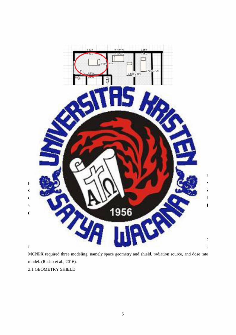
This research was carried out in Radiology Installation of one of Salatiga hospital area in
December 2015-January 2016. The Radiology Installation Plan used in Figure 3 is circled in red. The
source used is the x-ray plane brand Bucky Diagnostic with brand of Philips Optimus tube. Collimators,
diaphragms, indicator lights work well, voltage difference 150 kV, current 650 mA and 2.5 mm Al
filtration. Modeling and simulation Installation Radiology will use MCNPX software that is generally
designed for the purpose of simulating the traces of various types of particles with a wide range of
energy (Pelowitz, 2008).
2.2 Instrument
The material used for each material in this study is in accordance with the "Compilation of
Material Composition Data for Radiation Transport Modeling, Rev 1" which is a summary of material
composition and density for the use of radiation transport simulations (McConn, 2011).
2.3 Procedures
4
15
Figure 3. Installation Plan of Radiology unit in Salatiga area, simulation target is given a red
circle.
The construction of the building wall for the irradiation space is a radiation holder so it must be
planned in its construction. The radiation shield / radiation requirements for the radiology room are
determined by the type of equipment and radiation energy employed. For scratch radiation barrels, 15
cm diameter stoned concrete is required, and for wooden doors including the frame should be covered
with 2 mm thick lead, and equipped with radiation hazard warning and air regulation system as needed
(DEPKES RI, 1999).
3. Results
The radiation shield calculation using MCNPX is done through three stages of creating input
files, running the program with the computer, and analyzing the MCNPX output. In making the input
MCNPX required three modeling, namely space geometry and shield, radiation source, and dose rate
model. (Rasito et al., 2016).
3.1 GEOMETRY SHIELD
5

16
Figure 4. Geometry of Examination Room
The shield material to be simulated is concrete (McCann, 2011). The composition of atoms of
the concrete species to be simulated is shown in Table 1. Ball A shows the material containing air with
energy of 0.1 MeV, ball B contains a water material and ball C contains aerial material, which will see
the dose values absorbed from each material. Simulations performed at thickness of 10 cm to 20 cm to
1 cm were obtained by a certain thickness which gave the dose rate in shield 0.00 mrem / hour and
showed the dose for 100% workers well below the established NBD (BAPETEN, 2014).
3.2 OUTPUT RADIATION
(a)
6
6

17
(b)
Figure 5. The output of the outgoing radiation (red dots) at (a) and (b) of the MCNPX shows the
radiation coming out from the collector's point (point).
Base on figure 5 shows the source of the collimator made in the form of a point in cell 3, cell 4,
cell 6 indicating the area to be considered with the material used is concrete, while the 6 area cells are
viewed outside the box or the outer environment with air or oxygen material (O2). The simulation is
done for seven hundred million times the calculation (nps = 100000000). The data obtained pass the test
ten statistical checks on the results of running programs. The output of a photon particle with 100 KeV
energy from the source is not exceeding the NBD specified by BAPETEN for the x-ray inspection room,
the scattering of the red dots does not pass through the shield so that for the radiology examination room
with a maximum energy of 100 KeV is considered within safe limits.
4. Discussion
The current strength used is 650 mA and the voltage is 150 kV so as to find the number of
electrons generated with each second using the equation;
Nе = ί
𝑄 =
6,5 𝑥 10𝑒−1 𝐴
1,6 𝑥 10𝑒−19 𝐶= 4,0625 x 10⁻¹⁸/detik (1)
7
18
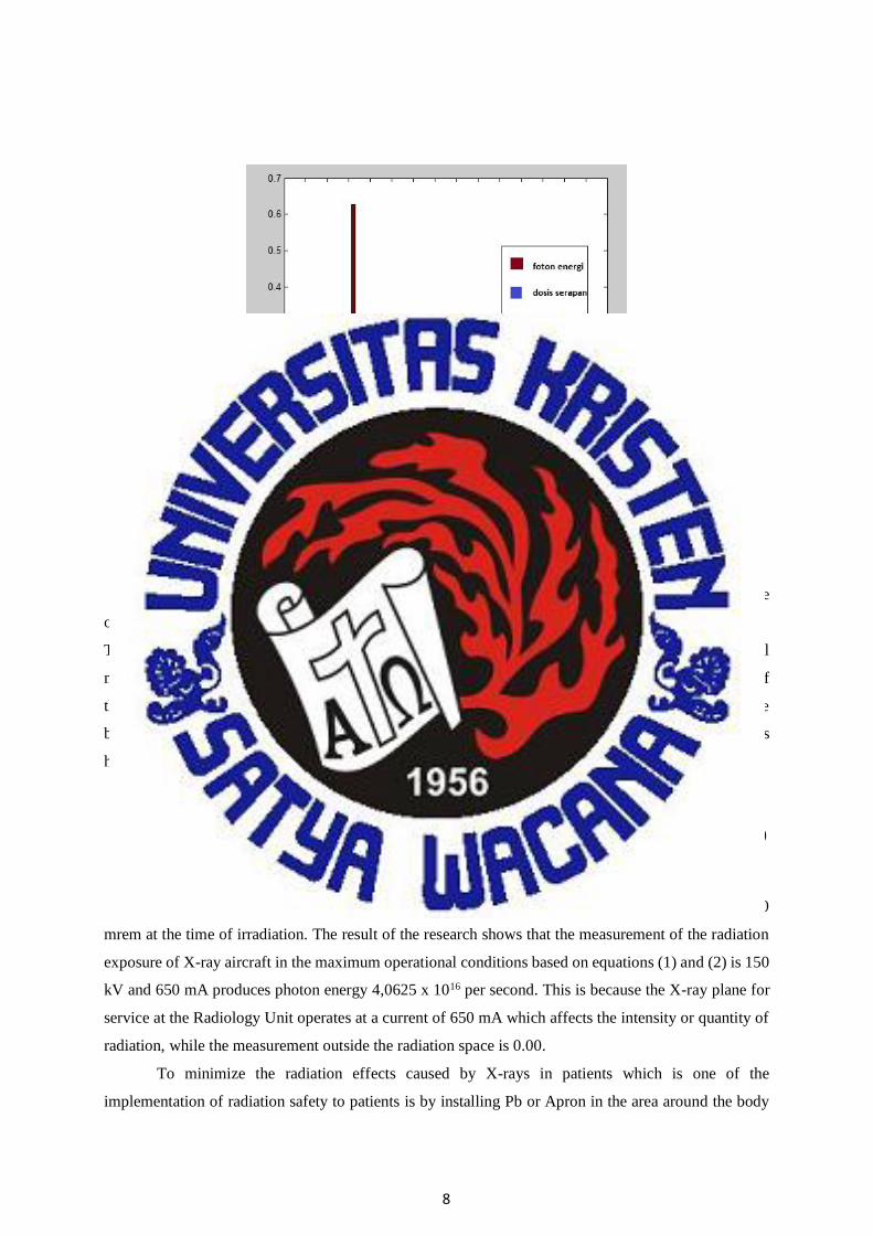
Figure 6. Shows the energy of the pounding particles (MeV) on the x-axis and the cross-sectional on
the y-axis, whereas the red color shows the photon energy and the blue color indicates the absorbed
dose.
Based on the above graph and the survey results data in the field of x-ray examination space
obtained:
The thickness of the radiation-retaining wall in the Radiological Unit constructed of concrete material
meets the radiation safety requirements for both radiation workers and the general public. The result of
the maximum thickness of theoretical radiation retention for the design of the room with a concrete
barrier is 15 cm. Since there is only 1% of electrons being converted into photon beams while 99% gets
hot then;
Nfoton = 1
100 x 4,0625 x 1018
= 1x10-2 x 4,0625x1018 (2)
= 4,0625x10¹⁶
From the measurement of the radiation dose outside the entire radiation retaining wall is 0.00
mrem at the time of irradiation. The result of the research shows that the measurement of the radiation
exposure of X-ray aircraft in the maximum operational conditions based on equations (1) and (2) is 150
kV and 650 mA produces photon energy 4,0625 x 10¹⁶ per second. This is because the X-ray plane for
service at the Radiology Unit operates at a current of 650 mA which affects the intensity or quantity of
radiation, while the measurement outside the radiation space is 0.00.
To minimize the radiation effects caused by X-rays in patients which is one of the
implementation of radiation safety to patients is by installing Pb or Apron in the area around the body
8
19
that is not done X-ray irradiation so that the X-rays are irradiated areas needed for the doctor's diagnosis.
The rate of radiation dose received by radiation workers and the general public around the Radiological
Unit is (0.00 mR / hr) away from the required NBD, meaning that the installation can be declared safe.
In general it can be stated that hospital managers are very concerned with the safety of the
community about the dangers of radiation. The construction of the radiology unit building should pay
attention to the quality of the material for radiation retention. In addition, radiation workers should
always use radiation protection equipment to be always controlled for radiation received by radiation
workers. The average dose received by radiation workers (119.5 mrem / yr). Compared with the NBD
stipulated in the decree of the Head of the Nuclear Power Supervisory Agency number 01 / Ka-Bapeten
/ V-99 well below 5000 mrem / yr or 50 mSv / yr. The result of One-Sample T Test statistic shows with
significant value 100% that radiation dosage is far below the determined NBD, so it can be stated that
service using X-ray plane in Radiology Unit is safe for radiation workers and the surrounding
community.
5. Conclusions
Radiological unit based on field survey and result of research and discussion, it can be concluded
that the rate of radiation exposure generated by the X-ray plane in the maximum operational kV of 150
kV and 650 mA produces 4,0625 x 10⁻¹⁸ / sec photon energy or based on the output at MCNPX
produced 0.1 MeV. The measurement result of dose rate received by workers and society outside the
radiation room is 0.00 mR / hr. The average dose of radiation workers from 2000 to 2007 was 119.5
mrem / year compared with the predetermined NBD, still well below the 100% significance value for
radiation workers and the surrounding environment.
6. References
(1) Rusmanto, 2012. Implementasi Tingkat Panduan Paparan Medik dan Uji Kesesuaian Pesawat
Sinar-x, BAPETEN, Jakarta
(2) PP No. 33 Tahun 2007, tentang Uji Keselamatan Radiasi Pengion dan Sumber Radioaktif
(3) BATAN, 2013. Dasar Fisika Radiasi Medik, Pusdiklat, BATAN, Jakart
(4) BATAN, 2013. Efek Radiasi Bagi Manusia, Pusdiklat, BATAN, Jakarta
(5) BAPETEN, 2011, tentang Keselamatan Radiasi Dalam Penggunaan Pesawat Sinar-x Radiologi
Diagnostik dan Intervensional, Jakarta
(6) Trikasjono T, Marjanto D, Nugroho A, 2007. Perancancangan Ruang Pengujian Kebocoran
Pesawat Sinar-x Rigaku 250 kV, STT BATAN, Yogyakarta
(7) Hiswara Eri, Tjahaja P. I, Wahyudi, 1996. Prosiding Presentasi Ilmiah
(8) Suwarno W, 1995. Mengenal Asas Proteksi Radiasi, Bandung
9
9

20
(9) Keputusan Kepala BAPETEN No. 1 tahun 1999. Keselamatan Radiasi Dalam Penggunaan Zat
Radioaktif, Jakarta
(10) Tamaela, 2010. Penelitian Unggulan tentang Nilai Batas Dosis
(11) Juniarti, 2016. Dosis Efektif Radiasi pada Pemeriksaan Thorax Pasien Tuberculosis Paru di
Instalasi Rumah Sakit, Jember
(12) NEA, 2010. MCUNED, MCNPX Exten sion for Using light Ion Evaluated Nuclear Data library
http://www.oecdnea.org/tools/abstract/detail/nea-1859/
(13) BATAN, 2016. Dasar-dasar Pemograman MCNPX, Yogyakarta
(14) Pelowitz Denise B, 2008. MCNPX user’s manual, version 2.6.0
http://www.mcnp.ir/admin/imgs/1354176297.2.6.0Users Manual.pdf
(15) McConn R J, Gesh C J, Pagh R T, Rucker R A, Williams R G. 2011. Compendium material
composition data for revision 1.
http://www.pnnl.gov/main/publications/external/technical_reports/pnnl-15870rev1.pdf
(16) BAPETEN, 2014. Surat Izin Bekerja Petugas Tertentu yang Bekerja di Instalasi yang
Memanfaatkan Sumber Radiasi Pengion.
(17) IAEA, 2014. Annual Report summarizes https://www.iaea.org/publications/reports/annual-
report-2014
10
10

21
LAMPIRAN
11

22
12