design and fabrication of stark whiteboard …umpir.ump.edu.my/3003/1/cd6140.pdf · bahan utama...
TRANSCRIPT
DESIGN AND FABRICATION OF STARK WHITEBOARD
KOK YIN HUI
Report submitted in partial fulfillment of the requirement for the award of
Diploma in Mechanical Engineering
Faculty of Mechanical Engineering
UNIVERSITI MALAYSIA PAHANG
DECEMBER 2011
v
ABSTRACT
This report presents about the design and fabrication of stark whiteboard
which the improvement is focus on the aspect of stability, mobility and
manufacturing cost. Whiteboard acts as an important equipment in human life
especially used in education, meeting purpose and instant messaging. However, its
mobility and stability do not always satisfy by its user due to the difficulty in
controlling the movement when transport from a place to another. In this project,
concept is generated through research on existing product in order to improve its
limitation. The major material used in fabricating the product is mild steel hollow bar.
It fabricates using three whiteboards and four castors. Besides, a mini stage is
attached to the product to improve its performance. SolidWorks Simulation Xpress
software is used for structure analysis in order to identify the maximum load the
product can support without deformation. The analysis conducted in three aspects,
which are stress analysis, displacement analysis and factor of safety analysis.
Methods and processes involved in this project include joining using MIG welding,
making hole with drilling method, bending using profile bending machine and
bending machine and also cutting using shearing machine. The idea of design and
fabrication for this whiteboard is based on student’s creativity.
vi
ABSTRAK
Laporan ini membentangkan perekaan dan fabrikasi papan putih yang stabil
di mana pengubahsuaian ditumpukan kepada skop kestabilan, mobiliti dan kos
pembuatan. Papan putih memainkan peranan penting dalam kehidupan manusia
terutamanya luas digunakan dalam perkuliahan, mesyuarat and peyampaian mesej.
Walau bagaimanapun, pergerakan dan kestabilan alat tersebut tidak sentiasa
memuaskan hati pengguna oleh sebab kesukaran dalam pengawalan pergerakan.
Dalam projek ini, konsep dihasilkan berasaskan penyelidikan ke atas produk sedia
ada untuk meningkatkan prestasinya. Bahan utama yang digunakan dalam produk
fabrikasi adalah bar keluli lembut. Ia dihasilkan dengan menggunakan tiga papan
putih dan empat roda. Selain itu, satu pentas mini dipasang pada produk tersebut
untuk meningkatkan prestasi. Di samping itu, SolidWork Simulation Xpress
digunakan untuk manjalankan analisis bagi mendapatkan had maksimum produk
tersebut dapat menampung. Analisis ini dijalankan dalam tiga aspek, iaitu analisis
tegasan, analisis anjakan dan analisis keselamatan. Kaedah dan proses yang terlibat
dalam projek ini termasuk menggunakan kimpalan MIG, membuat lubang dengan
menggunakan penggerudian, lentur menggunakan mesin profil lentur dan mesin
lentur dan juga memotong mengunakan mesin ricih. Idea perekaan dan fabrikasi
papan putih tersebut adalah dihasilkan berdasarkan kreativiti pelajar.
vii
TABLE OF CONTENTS
PAGE
SUPERVISOR DECLARATION ii
AUTHOR DECLARATION iii
ACKNOWLEDMENT iv
ABSTRACT v
ABSTRAK vi
TABLE OF CONTENTS vii
LIST OF TABLES xi
LIST OF FIGURE xii
CHAPTER 1 INTRODUCTION
1.1 Introduction 1
1.2 Background 1
1.3 Problem Statement 1
1.4 Objective 2
1.5 Scope 2
CHAPTER 2 LITERATURE REVIEW
2.1 Introduction 3
2.2 Types of Whiteboard 3
2.2.1 Wall-mounted whiteboard 3
2.2.2 Mobile stand whiteboard 4
2.2.3 Mobile double-sided stand whiteboard 5
2.2.4 Wing board 5
2.2.5 Compact board 6
2.2.6 Swing board 7
viii
2.3 Types of Material 8
2.3.1 Chromed steel 8
2.3.2 Wood 9
2.4 Types of Castor 9
2.4.1 Lockable castor with bearing 9
2.4.2 Non-lockable castor with bearing 10
2.4.3 Non-lockable castor without bearing 11
2.5 Stability 12
2.6 Mobility 13
2.7 Target Users 14
2.8 Types of Manufacturing Process 15
2.8.1 Welding 15
2.8.1.1 Arc Welding 15
2.8.1.2 MIG Welding 16
2.8.2 Shearing 17
2.8.3 Bending 17
2.8.4 Drilling 18
CHAPTER 3 METHODOLOGY
3.1 Introduction 20
3.2 Concept Generation 20
3.2.1 Concept 1 20
3.2.2 Concept 2 21
3.2.3 Concept 3 21
3.2.4 Concept 4 22
3.3 Concept Screening 22
3.4 Concept Selection 23
3.5 Concept Finalization 24
3.6 Material Selection 24
3.7 Structure Analysis 26
3.8 Fabrication 27
3.8.1 Fabrication flow 27
3.8.2 Fabrication process 28
ix
3.8.2.1 Dimension measuring 28
3.8.2.2 Material cutting 29
3.8.2.3 Shape forming 30
3.8.2.4 Drilling 30
3.8.2.5 Material joining 30
3.8.2.6 Finishing 31
CHAPTER 4 RESULTS AND DISCUSSION
4.1 Introduction 32
4.2 Result 32
4.3 Product Advantage or Function 33
4.3.1 Whiteboard 33
4.3.2 Angle player 33
4.3.3 Angle stopper 34
4.3.4 Whiteboard legs 34
4.3.5 Storage box 35
4.3.6 Pan 35
4.3.7 Stage 36
4.3.8 Castors 36
4.4 Structure Analysis 37
4.4.1 Whiteboard leg analysis 37
4.4.1.1 Whiteboard leg stress analysis 38
4.4.1.2 Whiteboard leg displacement analysis 39
4.4.1.3 Whiteboard leg factor of safety analysis 40
4.4.2 Stage analysis 41
4.4.2.1 Stage stress analysis 41
4.4.2.2 Stage displacement analysis 42
4.4.2.3 Stage factor of safety analysis 43
4.5 Cost Analysis 43
4.6 Discussion 44
CHAPTER 5 CONCLUSION
5.1 Introduction 46
5.2 Conclusion 46
5.3 Recommendation 47
x
REFERENCES 48
APPENDIXES 49
A Project Flow Chart 49
B Project Gantt Chart 50
C Product Isometric View 51
D Product 2D View 52
E Stage 2D View 53
xi
LIST OF TABLES
Table No. Page
2.1 Wall-mounted whiteboard overview 3
2.2 Mobile stand whiteboard overview 4
2.3 Mobile double-sided stand whiteboard overview 5
2.4 Wing board overview 6
2.5 Compact board overview 6
2.6 Lockable castor with bearing overview 10
2.7 Non-lockable castor with bearing overview 10
2.8 Non-lockable castor without bearing overview 11
3.1 Concept screening 23
3.2 Bill of material 25
4.1 Stress analysis of whiteboard leg 38
4.2 Displacement analysis of whiteboard leg 39
4.3 Stress analysis of stage 41
4.4 Displacement analysis of stage 42
4.5 Cost Analysis 44
xii
LIST OF FIGURES
Figure No. Page
2.1 Wall-mounted whiteboard 4
2.2 Mobile stand whiteboard 4
2.3 Mobile double-sided stand whiteboard 5
2.4 Wing board 6
2.5 Compact board 7
2.6 Swing board 7
2.7 Whiteboard stand made from chromed steel 8
2.8 Whiteboard stand made from wood 9
2.9 Lockable castor with bearing 10
2.10 Non-lockable castor with bearing 11
2.11 Non-lockable castor without bearing 11
2.12 Center of gravity 12
2.13 Six degree of freedom 13
2.14 Graph of height to weight 14
2.15 Arc Welding 16
2.16 MIG Welding 16
2.17 Metal shearing 17
2.18 Bending machine 18
2.19 Drilling Machine 19
3.1 Concept 1 20
3.2 Concept 2 21
3.3 Concept 3 21
3.4 Concept 4 22
3.5 Final design concept 24
3.6 Final design 24
3.7 Components of final design 25
3.8 Structure analysis flow 26
3.9 Fabrication flow chart 28
3.10 Measuring process 29
xiii
3.11 Cutting process 29
3.12 Material joining (Nailing) 30
3.13 Finishing 31
4.1 Final product in closed condition 32
4.2 Final product in opened condition 32
4.3 Whiteboards 33
4.4 Angle player 33
4.5 Angle stopper 34
4.6 Whiteboard leg 35
4.7 Storage box in closed condition 35
4.8 Storage box in opened condition 35
4.9 Pan 36
4.10 Stage 36
4.11 Front castor 37
4.12 Back castor 37
4.13 Stress analysis of whiteboard leg 38
4.14 Displacement analysis of whiteboard leg 39
4.15 Factor of safety analysis of whiteboard leg 40
4.16 Stress analysis of stage 41
4.17 Displacement analysis of stage 42
4.18 Factor of safety analysis of stage 43
4.19 Non-lockable castor without bearing 45
4.20 Non-lockable castor with bearing 45
CHAPTER 1
INTRODUCTION
1.1 INTRODUCTION
This chapter explained about the project objective, project background,
project scope and problem statement that been conducted.
1.2 BACKGROUND
Whiteboard is a smooth surface which writing using a marker and
erased using a duster. It is available in various size and design to suit the user
requirement. Whiteboard can be divided into two main categories, which are
“Moveable Whiteboard” and “Non-Moveable Whiteboard”. “Moveable
Whiteboard” refers to whiteboards that are designed with castors for better
mobility. While for “Non-Moveable Whiteboard” refers to whiteboards that
attached to wall and used in a completely static condition. Nowadays,
whiteboard is widely used for meeting purpose, teaching purpose and instant
messaging.
1.3 PROBLEM STATEMENT
One of the common problems faced by the whiteboard in the market
is its low mobility. For “wall-attached whiteboard”, obviously it has to be
fixed in a completely static condition. For “whiteboard with stand and
castors”, there is a difficulty in controlling the movement when it is being
pushed by single person. Moreover, whiteboard has low stability which tends
2
to shack forward and backward during writing. Besides, most of the
whiteboard designs do not have a proper storage site for whiteboard writing
tools. This causes dust deposited, or may cause falling of writing tools
especially when the whiteboard is being moved.
1.4 OBJECTIVE
The objective of the project is to design and fabricate a stark
whiteboard with higher mobility and stability at a lower manufacturing cost.
1.5 SCOPE
This project is limited within the following scopes, which are:
i. Fabricate a stable and moveable whiteboard which remain
static during writing and is easy to be moved.
ii. Design a storage site for whiteboard writing tools with one
duster and three markers only.
iii. The weight of the product less than 70kg.
iv. The height of the product less than 220cm.
v. The product fabricate with less than five castors.
3
CHAPTER 2
LITERATURE REVIEW
2.1 INTRODUCTION
This chapter explains the review of market survey and past research
effort related to whiteboard. Reviews of other relevant research studies are
also provided. The literature has been studied on types of whiteboard,
material usage and fabrication methods.
2.2 TYPES OF WHITEBOARD
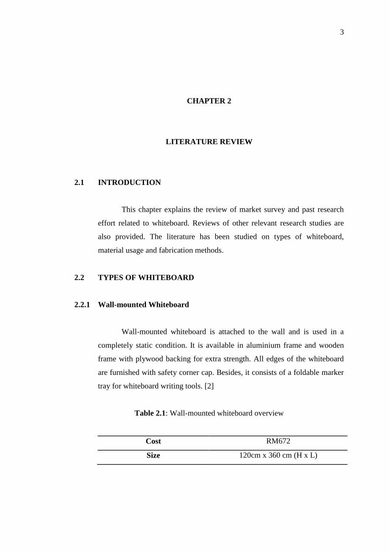
2.2.1 Wall-mounted Whiteboard
Wall-mounted whiteboard is attached to the wall and is used in a
completely static condition. It is available in aluminium frame and wooden
frame with plywood backing for extra strength. All edges of the whiteboard
are furnished with safety corner cap. Besides, it consists of a foldable marker
tray for whiteboard writing tools. [2]
Table 2.1: Wall-mounted whiteboard overview
Cost RM672
Size 120cm x 360 cm (H x L)
4
Figure 2.1: Wall-mounted whiteboard
Source: Banhoh Sdn Bhd
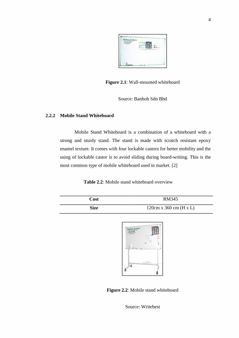
2.2.2 Mobile Stand Whiteboard
Mobile Stand Whiteboard is a combination of a whiteboard with a
strong and sturdy stand. The stand is made with scratch resistant epoxy
enamel texture. It comes with four lockable castors for better mobility and the
using of lockable castor is to avoid sliding during board-writing. This is the
most common type of mobile whiteboard used in market. [2]
Table 2.2: Mobile stand whiteboard overview
Cost RM345
Size 120cm x 360 cm (H x L)
Figure 2.2: Mobile stand whiteboard
Source: Writebest
5
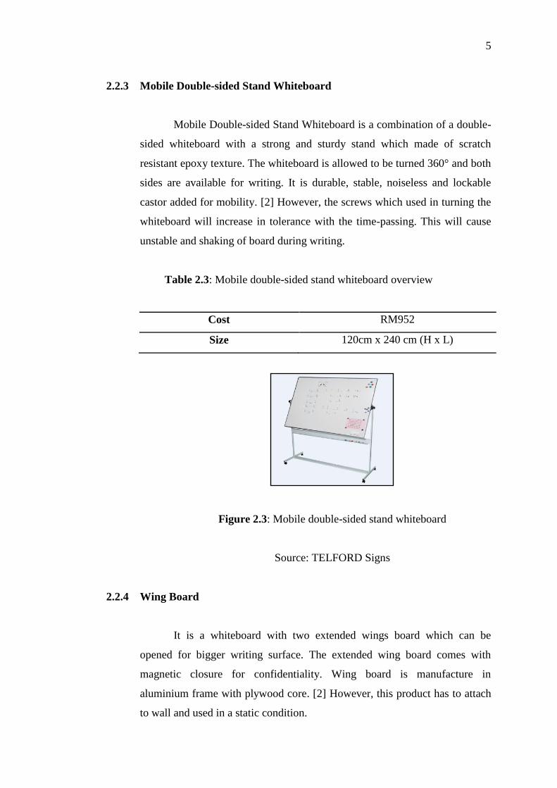
2.2.3 Mobile Double-sided Stand Whiteboard
Mobile Double-sided Stand Whiteboard is a combination of a double-
sided whiteboard with a strong and sturdy stand which made of scratch
resistant epoxy texture. The whiteboard is allowed to be turned 360° and both
sides are available for writing. It is durable, stable, noiseless and lockable
castor added for mobility. [2] However, the screws which used in turning the
whiteboard will increase in tolerance with the time-passing. This will cause
unstable and shaking of board during writing.
Table 2.3: Mobile double-sided stand whiteboard overview
Cost RM952
Size 120cm x 240 cm (H x L)
Figure 2.3: Mobile double-sided stand whiteboard
Source: TELFORD Signs
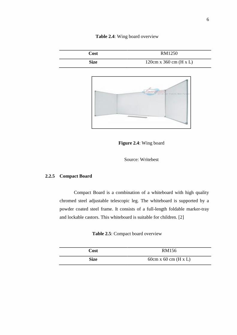
2.2.4 Wing Board
It is a whiteboard with two extended wings board which can be
opened for bigger writing surface. The extended wing board comes with
magnetic closure for confidentiality. Wing board is manufacture in
aluminium frame with plywood core. [2] However, this product has to attach
to wall and used in a static condition.
6
Table 2.4: Wing board overview
Cost RM1250
Size 120cm x 360 cm (H x L)
Figure 2.4: Wing board
Source: Writebest
2.2.5 Compact Board
Compact Board is a combination of a whiteboard with high quality
chromed steel adjustable telescopic leg. The whiteboard is supported by a
powder coated steel frame. It consists of a full-length foldable marker-tray
and lockable castors. This whiteboard is suitable for children. [2]
Table 2.5: Compact board overview
Cost RM156
Size 60cm x 60 cm (H x L)
7
Figure 2.5: Compact board
Source: Writebest
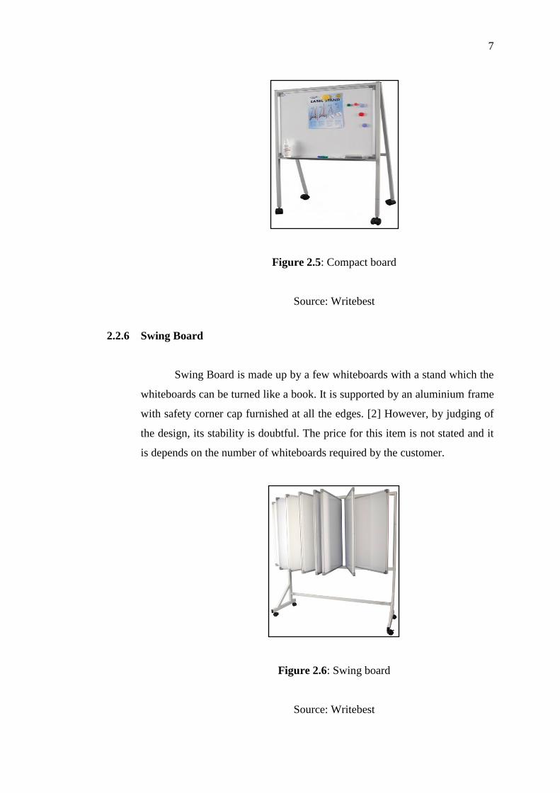
2.2.6 Swing Board
Swing Board is made up by a few whiteboards with a stand which the
whiteboards can be turned like a book. It is supported by an aluminium frame
with safety corner cap furnished at all the edges. [2] However, by judging of
the design, its stability is doubtful. The price for this item is not stated and it
is depends on the number of whiteboards required by the customer.
Figure 2.6: Swing board
Source: Writebest
8
2.3 TYPES OF MATERIAL
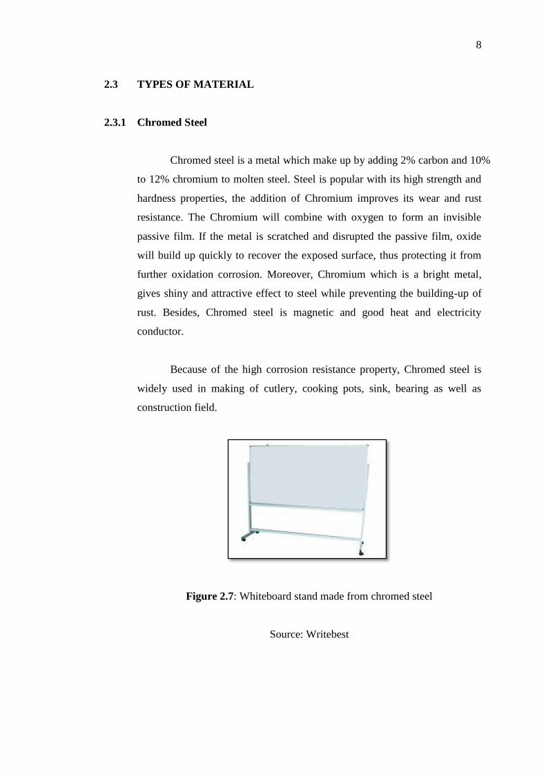
2.3.1 Chromed Steel
Chromed steel is a metal which make up by adding 2% carbon and 10%
to 12% chromium to molten steel. Steel is popular with its high strength and
hardness properties, the addition of Chromium improves its wear and rust
resistance. The Chromium will combine with oxygen to form an invisible
passive film. If the metal is scratched and disrupted the passive film, oxide
will build up quickly to recover the exposed surface, thus protecting it from
further oxidation corrosion. Moreover, Chromium which is a bright metal,
gives shiny and attractive effect to steel while preventing the building-up of
rust. Besides, Chromed steel is magnetic and good heat and electricity
conductor.
Because of the high corrosion resistance property, Chromed steel is
widely used in making of cutlery, cooking pots, sink, bearing as well as
construction field.
Figure 2.7: Whiteboard stand made from chromed steel
Source: Writebest
9
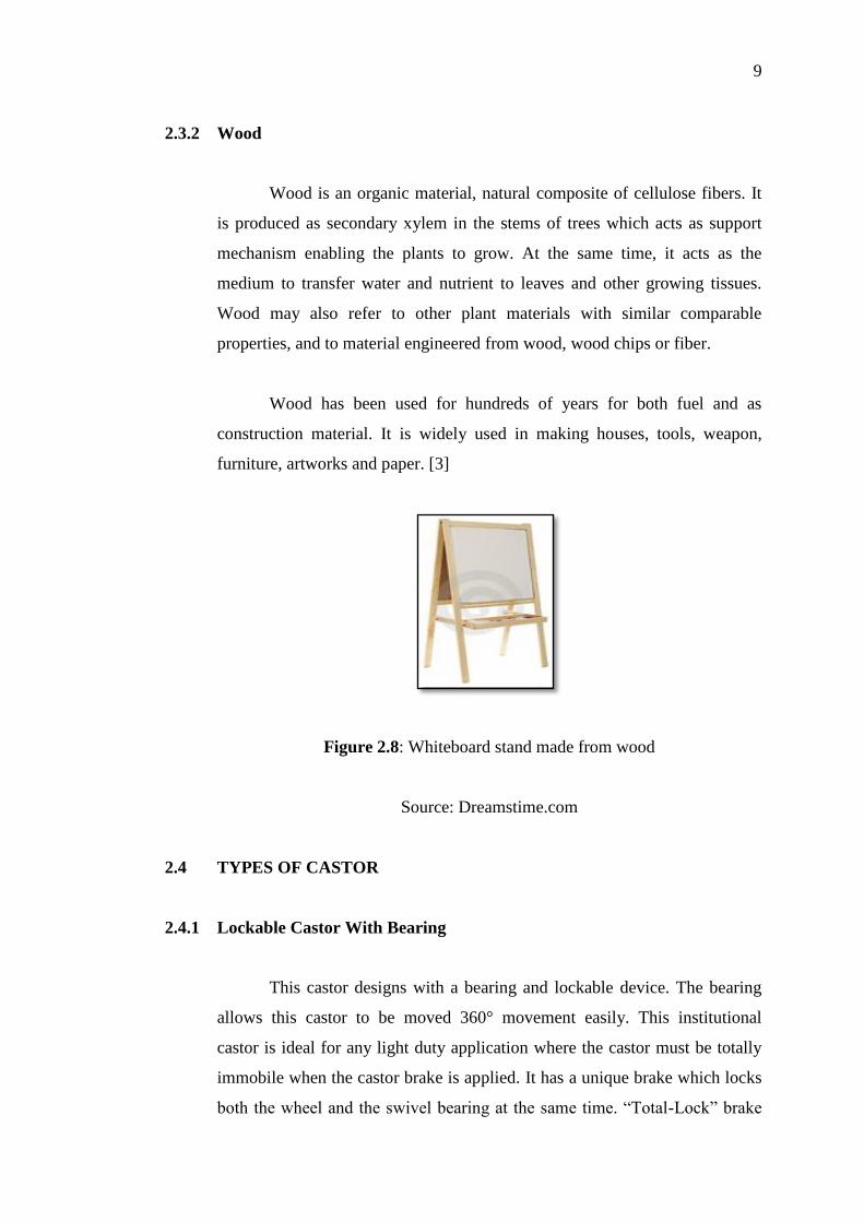
2.3.2 Wood
Wood is an organic material, natural composite of cellulose fibers. It
is produced as secondary xylem in the stems of trees which acts as support
mechanism enabling the plants to grow. At the same time, it acts as the
medium to transfer water and nutrient to leaves and other growing tissues.
Wood may also refer to other plant materials with similar comparable
properties, and to material engineered from wood, wood chips or fiber.
Wood has been used for hundreds of years for both fuel and as
construction material. It is widely used in making houses, tools, weapon,
furniture, artworks and paper. [3]
Figure 2.8: Whiteboard stand made from wood
Source: Dreamstime.com
2.4 TYPES OF CASTOR
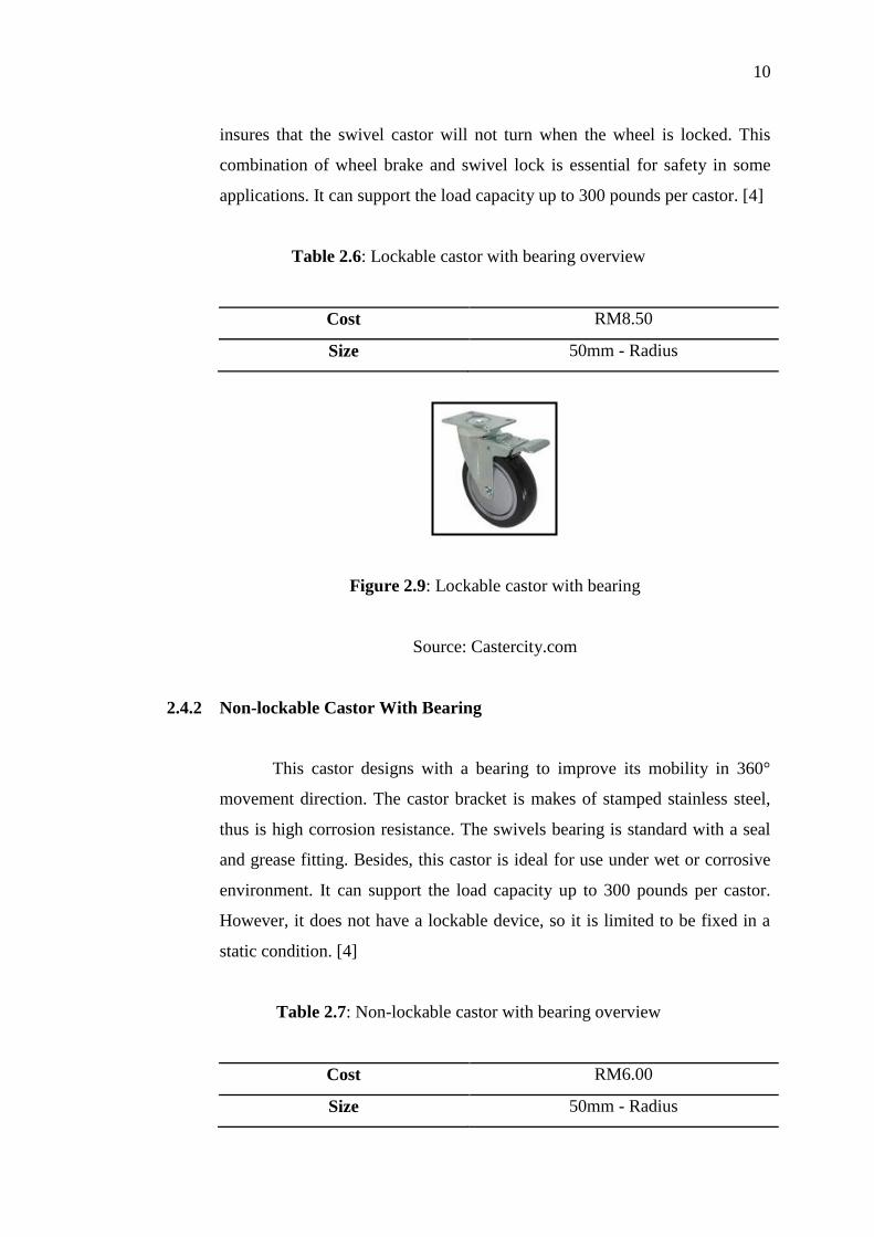
2.4.1 Lockable Castor With Bearing
This castor designs with a bearing and lockable device. The bearing
allows this castor to be moved 360° movement easily. This institutional
castor is ideal for any light duty application where the castor must be totally
immobile when the castor brake is applied. It has a unique brake which locks
both the wheel and the swivel bearing at the same time. “Total-Lock” brake
10
insures that the swivel castor will not turn when the wheel is locked. This
combination of wheel brake and swivel lock is essential for safety in some
applications. It can support the load capacity up to 300 pounds per castor. [4]
Table 2.6: Lockable castor with bearing overview
Cost RM8.50
Size 50mm - Radius
Figure 2.9: Lockable castor with bearing
Source: Castercity.com
2.4.2 Non-lockable Castor With Bearing
This castor designs with a bearing to improve its mobility in 360°
movement direction. The castor bracket is makes of stamped stainless steel,
thus is high corrosion resistance. The swivels bearing is standard with a seal
and grease fitting. Besides, this castor is ideal for use under wet or corrosive
environment. It can support the load capacity up to 300 pounds per castor.
However, it does not have a lockable device, so it is limited to be fixed in a
static condition. [4]
Table 2.7: Non-lockable castor with bearing overview
Cost RM6.00
Size 50mm - Radius
11
Figure 2.10: Non-lockable castor with bearing
Source: Castercity.com
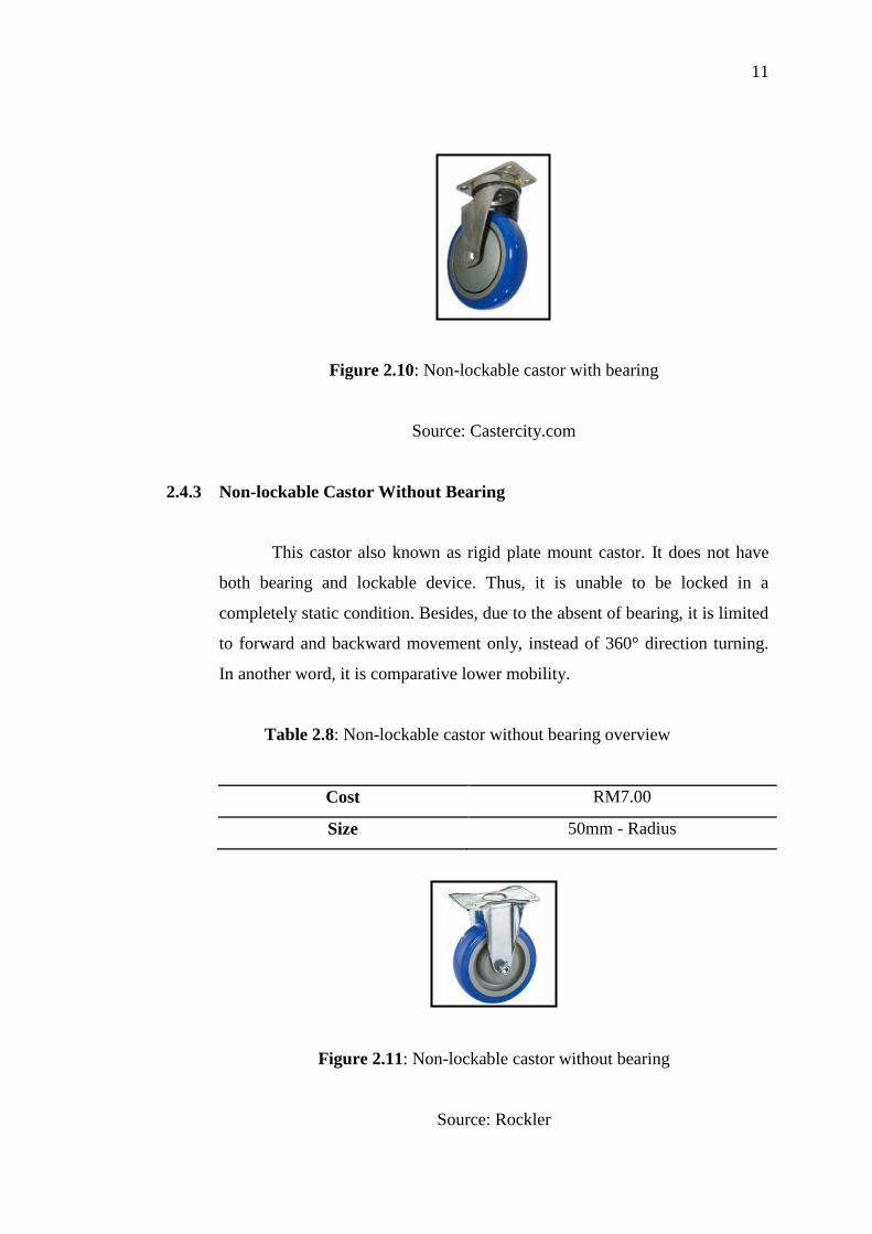
2.4.3 Non-lockable Castor Without Bearing
This castor also known as rigid plate mount castor. It does not have
both bearing and lockable device. Thus, it is unable to be locked in a
completely static condition. Besides, due to the absent of bearing, it is limited
to forward and backward movement only, instead of 360° direction turning.
In another word, it is comparative lower mobility.
Table 2.8: Non-lockable castor without bearing overview
Cost RM7.00
Size 50mm - Radius
Figure 2.11: Non-lockable castor without bearing
Source: Rockler
12
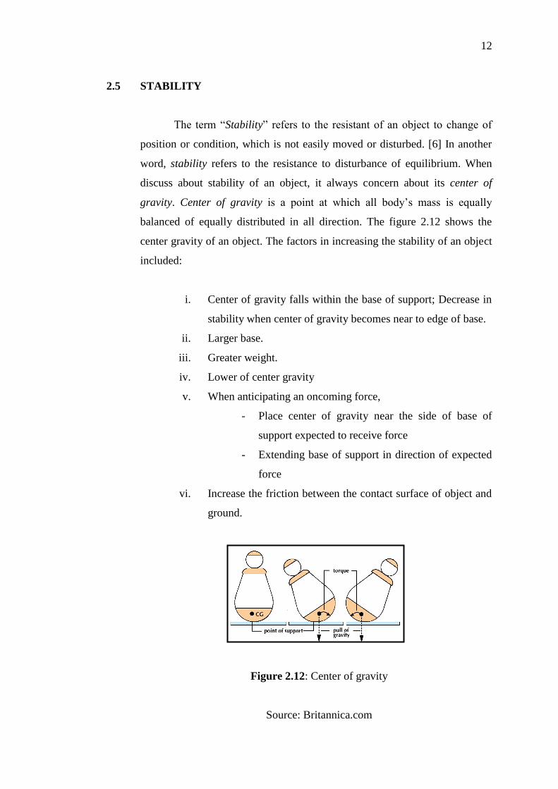
2.5 STABILITY
The term “Stability” refers to the resistant of an object to change of
position or condition, which is not easily moved or disturbed. [6] In another
word, stability refers to the resistance to disturbance of equilibrium. When
discuss about stability of an object, it always concern about its center of
gravity. Center of gravity is a point at which all body’s mass is equally
balanced of equally distributed in all direction. The figure 2.12 shows the
center gravity of an object. The factors in increasing the stability of an object
included:
i. Center of gravity falls within the base of support; Decrease in
stability when center of gravity becomes near to edge of base.
ii. Larger base.
iii. Greater weight.
iv. Lower of center gravity
v. When anticipating an oncoming force,
- Place center of gravity near the side of base of
support expected to receive force
- Extending base of support in direction of expected
force
vi. Increase the friction between the contact surface of object and
ground.
Figure 2.12: Center of gravity
Source: Britannica.com
13
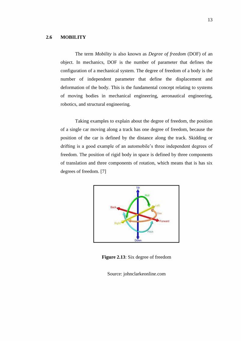
2.6 MOBILITY
The term Mobility is also known as Degree of freedom (DOF) of an
object. In mechanics, DOF is the number of parameter that defines the
configuration of a mechanical system. The degree of freedom of a body is the
number of independent parameter that define the displacement and
deformation of the body. This is the fundamental concept relating to systems
of moving bodies in mechanical engineering, aeronautical engineering,
robotics, and structural engineering.
Taking examples to explain about the degree of freedom, the position
of a single car moving along a track has one degree of freedom, because the
position of the car is defined by the distance along the track. Skidding or
drifting is a good example of an automobile’s three independent degrees of
freedom. The position of rigid body in space is defined by three components
of translation and three components of rotation, which means that is has six
degrees of freedom. [7]
Figure 2.13: Six degree of freedom
Source: johnclarkeonline.com
14
2.7 TARGET USERS
Nowadays, whiteboard is widely used in human daily life especially
for education and meeting purpose. Many offices, meeting rooms, schools,
universities and tuition centers are using whiteboard in sharing of information.
In all of these whiteboard usages, the users are mostly adult with the average
age above 20 years old.
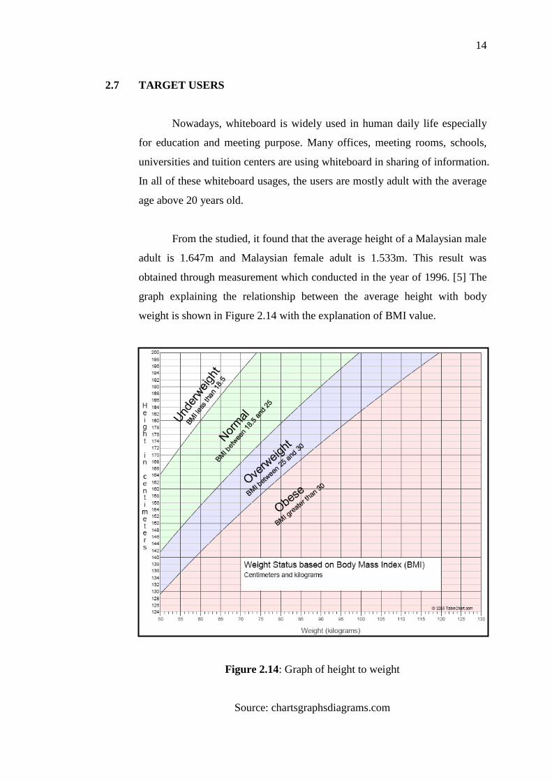
From the studied, it found that the average height of a Malaysian male
adult is 1.647m and Malaysian female adult is 1.533m. This result was
obtained through measurement which conducted in the year of 1996. [5] The
graph explaining the relationship between the average height with body
weight is shown in Figure 2.14 with the explanation of BMI value.
Figure 2.14: Graph of height to weight
Source: chartsgraphsdiagrams.com
15
2.8 TYPES OF MANUFACTURING PROCESS
2.8.1 Welding
Welding is a fabrication process that joins materials, usually metals or
thermoplastics by causing coalescence with pressure and heat. The concept is
to melt the metal and adding a filler material to form a small pool of molten
material, which cools and become a strong joint.
Many energy sources can be used for welding, which includes gas
flame, electric arc, laser, electron beam, friction and ultrasound. Besides,
welding can be performed in various environments, like open air, underwater,
or even outer space. However, welding is considered as a hazardous activity
which may lead to burns, vision damage and inhalation of poisonous gases
and fumes. Hence safety precaution like wearing face mask in carrying out
welding is important. [8]
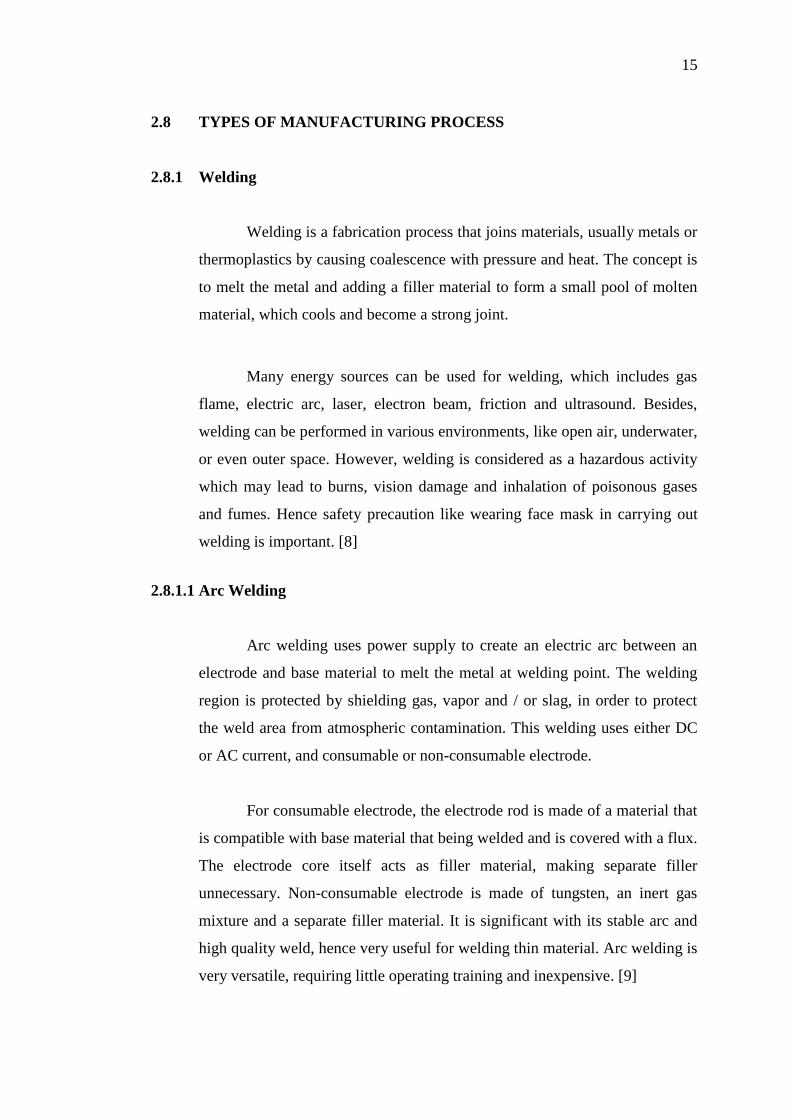
2.8.1.1 Arc Welding
Arc welding uses power supply to create an electric arc between an
electrode and base material to melt the metal at welding point. The welding
region is protected by shielding gas, vapor and / or slag, in order to protect
the weld area from atmospheric contamination. This welding uses either DC
or AC current, and consumable or non-consumable electrode.
For consumable electrode, the electrode rod is made of a material that
is compatible with base material that being welded and is covered with a flux.
The electrode core itself acts as filler material, making separate filler
unnecessary. Non-consumable electrode is made of tungsten, an inert gas
mixture and a separate filler material. It is significant with its stable arc and
high quality weld, hence very useful for welding thin material. Arc welding is
very versatile, requiring little operating training and inexpensive. [9]
16
Figure 2.15: Arc welding
Source: Wikipedia.org
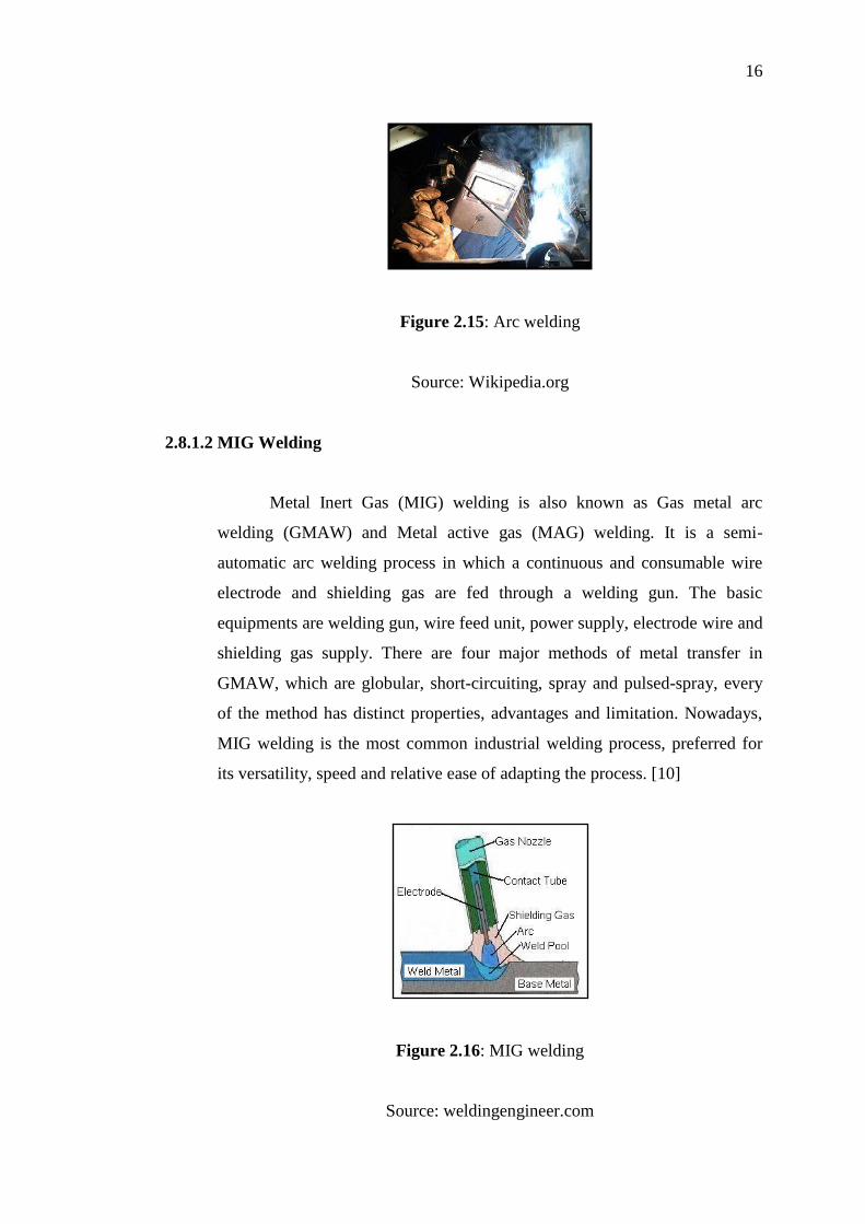
2.8.1.2 MIG Welding
Metal Inert Gas (MIG) welding is also known as Gas metal arc
welding (GMAW) and Metal active gas (MAG) welding. It is a semi-
automatic arc welding process in which a continuous and consumable wire
electrode and shielding gas are fed through a welding gun. The basic
equipments are welding gun, wire feed unit, power supply, electrode wire and
shielding gas supply. There are four major methods of metal transfer in
GMAW, which are globular, short-circuiting, spray and pulsed-spray, every
of the method has distinct properties, advantages and limitation. Nowadays,
MIG welding is the most common industrial welding process, preferred for
its versatility, speed and relative ease of adapting the process. [10]
Figure 2.16: MIG welding
Source: weldingengineer.com
17
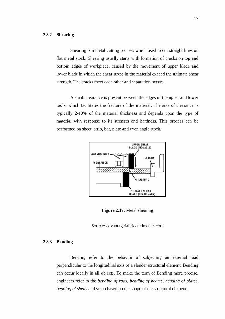
2.8.2 Shearing
Shearing is a metal cutting process which used to cut straight lines on
flat metal stock. Shearing usually starts with formation of cracks on top and
bottom edges of workpiece, caused by the movement of upper blade and
lower blade in which the shear stress in the material exceed the ultimate shear
strength. The cracks meet each other and separation occurs.
A small clearance is present between the edges of the upper and lower
tools, which facilitates the fracture of the material. The size of clearance is
typically 2-10% of the material thickness and depends upon the type of
material with response to its strength and hardness. This process can be
performed on sheet, strip, bar, plate and even angle stock.
Figure 2.17: Metal shearing
Source: advantagefabricatedmetals.com
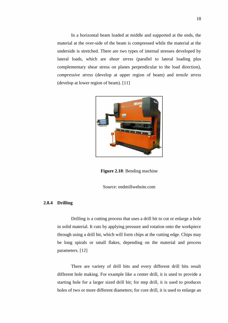
2.8.3 Bending
Bending refer to the behavior of subjecting an external load
perpendicular to the longitudinal axis of a slender structural element. Bending
can occur locally in all objects. To make the term of Bending more precise,
engineers refer to the bending of rods, bending of beams, bending of plates,
bending of shells and so on based on the shape of the structural element.
18
In a horizontal beam loaded at middle and supported at the ends, the
material at the over-side of the beam is compressed while the material at the
underside is stretched. There are two types of internal stresses developed by
lateral loads, which are shear stress (parallel to lateral loading plus
complementary shear stress on planes perpendicular to the load direction),
compressive stress (develop at upper region of beam) and tensile stress
(develop at lower region of beam). [11]
Figure 2.18: Bending machine
Source: endmillwebsite.com
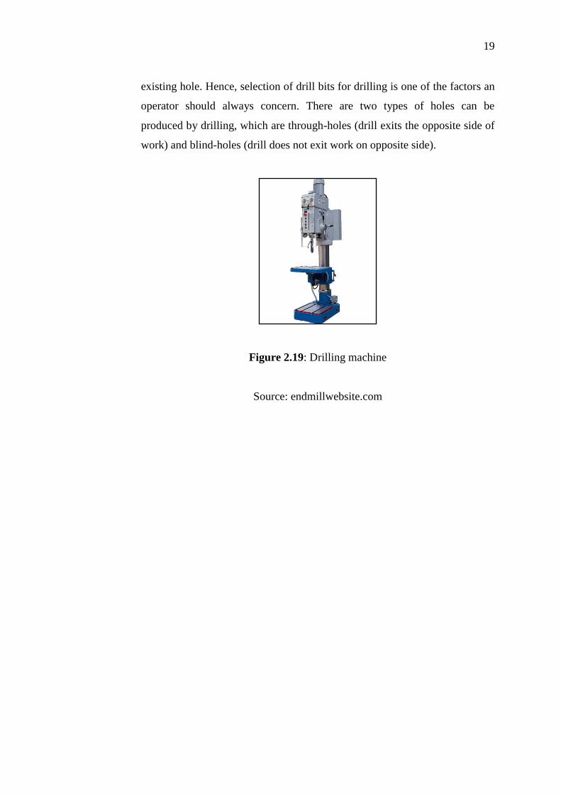
2.8.4 Drilling
Drilling is a cutting process that uses a drill bit to cut or enlarge a hole
in solid material. It cuts by applying pressure and rotation onto the workpiece
through using a drill bit, which will form chips at the cutting edge. Chips may
be long spirals or small flakes, depending on the material and process
parameters. [12]
There are variety of drill bits and every different drill bits result
different hole making. For example like a center drill, it is used to provide a
starting hole for a larger sized drill bit; for step drill, it is used to produces
holes of two or more different diameters; for core drill, it is used to enlarge an
19
existing hole. Hence, selection of drill bits for drilling is one of the factors an
operator should always concern. There are two types of holes can be
produced by drilling, which are through-holes (drill exits the opposite side of
work) and blind-holes (drill does not exit work on opposite side).
Figure 2.19: Drilling machine
Source: endmillwebsite.com
20
CHAPTER 3
METHODOLOGY
3.1 INTRODUCTION
This chapter discusses about the concept designs that have been
develop during concept generation. The designs had undergoes concept
selection and lastly the finalization stage before proceed to fabrication of
product. It also explained about the tools and fabrication planning for the
project.
3.2 CONCEPT GENERATION
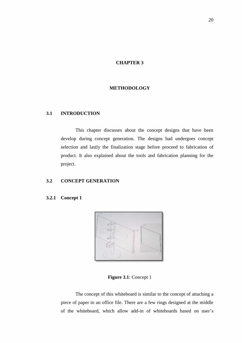
3.2.1 Concept 1
Figure 3.1: Concept 1
The concept of this whiteboard is similar to the concept of attaching a
piece of paper to an office file. There are a few rings designed at the middle
of the whiteboard, which allow add-in of whiteboards based on user’s
21
requirement. The disadvantage of this design is that, the whiteboard will tense
to shake during writing.
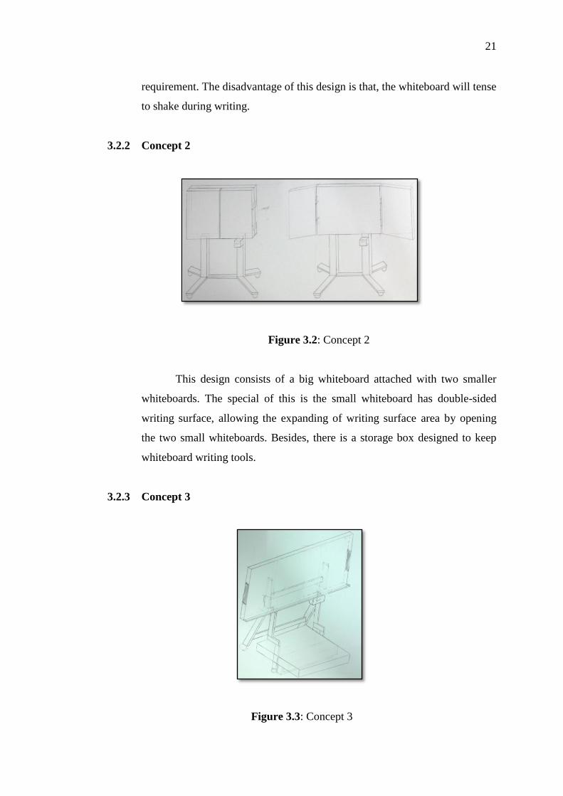
3.2.2 Concept 2
Figure 3.2: Concept 2
This design consists of a big whiteboard attached with two smaller
whiteboards. The special of this is the small whiteboard has double-sided
writing surface, allowing the expanding of writing surface area by opening
the two small whiteboards. Besides, there is a storage box designed to keep
whiteboard writing tools.
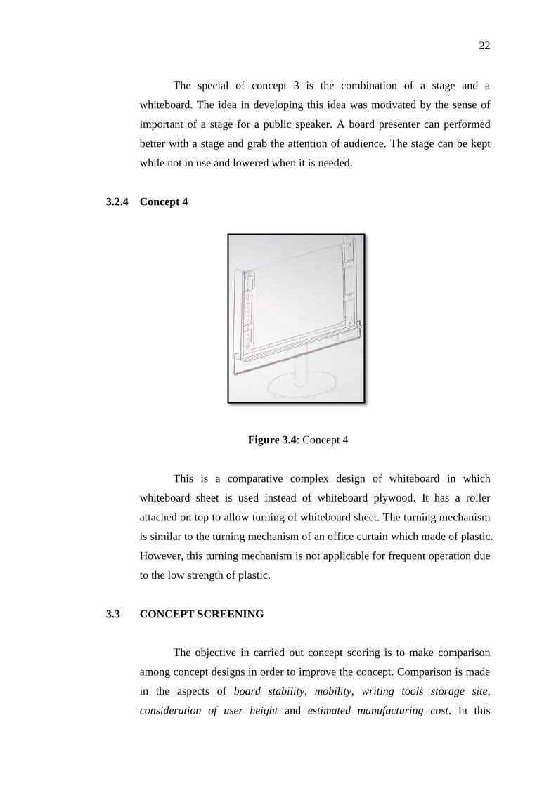
3.2.3 Concept 3
Figure 3.3: Concept 3
22
The special of concept 3 is the combination of a stage and a
whiteboard. The idea in developing this idea was motivated by the sense of
important of a stage for a public speaker. A board presenter can performed
better with a stage and grab the attention of audience. The stage can be kept
while not in use and lowered when it is needed.
3.2.4 Concept 4
Figure 3.4: Concept 4
This is a comparative complex design of whiteboard in which
whiteboard sheet is used instead of whiteboard plywood. It has a roller
attached on top to allow turning of whiteboard sheet. The turning mechanism
is similar to the turning mechanism of an office curtain which made of plastic.
However, this turning mechanism is not applicable for frequent operation due
to the low strength of plastic.
3.3 CONCEPT SCREENING
The objective in carried out concept scoring is to make comparison
among concept designs in order to improve the concept. Comparison is made
in the aspects of board stability, mobility, writing tools storage site,
consideration of user height and estimated manufacturing cost. In this

23
concept scoring, I had chosen mobile double-sided stand whiteboard as the
reference. The result is shown in Table 3.1.
Table 3.1: Concept screening
SELECTION CRITERIA 1 2 3 4 REF.
Board stability (during writing) 0 + + - 0
Mobility + + + 0 0
Writing tools storage site + + + + 0
Total writing surface 0 + - + 0
Consideration of user height 0 0 + + 0
Estimated manufacturing cost + + + + 0
PLUSES 3 5 5 4
SAMES 3 1 0 1
MINUSES 0 0 1 1
NET 3 5 4 3
RANK 3 1 2 4
Notes:
+ = Better than reference
- = Worse than reference
0 = Same as reference
3.4 CONCEPT SELECTION
Referring to the result of concept scoring, ranking number 1 goes for
concept 2, ranking number 2 goes for concept 3, followed by concept 1 and 4.
Hence in deciding my final concept, I would like to fabricate the best
whiteboard with the combination of advantages between concepts ranking 1
and 2. For the aspect of total writing surface, concept 2 shows a better result
but for the aspect of consideration of user height, concept 3 can perform
better. Thus, by combining the advantages, a new final design concept is
obtained and is shown in figure 3.5.
24
Figure 3.5: Final design concept
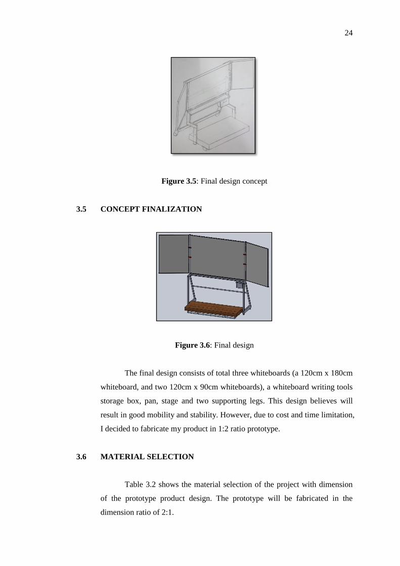
3.5 CONCEPT FINALIZATION
Figure 3.6: Final design
The final design consists of total three whiteboards (a 120cm x 180cm
whiteboard, and two 120cm x 90cm whiteboards), a whiteboard writing tools
storage box, pan, stage and two supporting legs. This design believes will
result in good mobility and stability. However, due to cost and time limitation,
I decided to fabricate my product in 1:2 ratio prototype.
3.6 MATERIAL SELECTION
Table 3.2 shows the material selection of the project with dimension
of the prototype product design. The prototype will be fabricated in the
dimension ratio of 2:1.