dell precision m3800...perhatian agar data tidak hilang, simpan dan tutup semua file yang terbuka,...
TRANSCRIPT
Dell Precision M3800Owner's Manual
Regulatory Model: P31FRegulatory Type: P31F001
Catatan, perhatian, dan peringatan
CATATAN Sebuah CATATAN menandakan informasi penting yang membantu Anda untuk menggunakan yang terbaik dari
produk Anda.
PERHATIAN PERHATIAN menunjukkan kemungkinan terjadinya kerusakan pada perangkat keras atau hilangnya data,
dan memberi tahu Anda mengenai cara menghindari masalah tersebut.
PERINGATAN PERINGATAN menunjukkan potensi kerusakan harta benda, cedera pribadi, atau kematian
Copyright © 2017 Dell Inc. atau anak perusahaannya. Semua hak dilindungi undang-undang. Dell, EMC, dan merek dagang lainnya adalah merek dagang dari Dell Inc. atau anak perusahaannya. Merek dagang lainnya dapat merupakan merek dagang dari pemiliknya masing-masing.
2015 - 05
Rev. A02
1 Mengerjakan komputer Anda......................................................................................................... 5Sebelum mengerjakan bagian dalam komputer..................................................................................................................5Mematikan Komputer............................................................................................................................................................6Setelah mengerjakan bagian dalam komputer................................................................................................................... 6
2 Melepaskan dan memasang komponen........................................................................................... 7Alat bantu yang direkomendasikan...................................................................................................................................... 7System Overview...................................................................................................................................................................7Removing the Base Cover....................................................................................................................................................8Installing the Base Cover...................................................................................................................................................... 9Removing the System Badge Flap...................................................................................................................................... 9Installing the System Badge Flap....................................................................................................................................... 10Removing the Battery......................................................................................................................................................... 10Installing the Battery.............................................................................................................................................................11Removing the Memory Module(s)......................................................................................................................................11Installing the Memory Module(s)........................................................................................................................................ 11Removing the Touchpad..................................................................................................................................................... 12Installing the Touchpad........................................................................................................................................................12Removing the Hard Drive.................................................................................................................................................... 13Installing the Hard Drive...................................................................................................................................................... 13Removing the Speakers ................................................................................................................................................. 14Installing the Speakers......................................................................................................................................................... 14Removing the WLAN Card..................................................................................................................................................14Installing the WLAN Card.................................................................................................................................................... 15Removing the Coin-Cell Battery........................................................................................................................................ 15Installing the Coin-Cell Battery........................................................................................................................................... 16Removing the mSATA Card................................................................................................................................................16Installing the mSATA Card.................................................................................................................................................. 17Removing the Fans ............................................................................................................................................................. 17Installing the Fans.................................................................................................................................................................18Removing the Heatsink....................................................................................................................................................... 18Installing the Heatsink..........................................................................................................................................................19Removing the Power Connector....................................................................................................................................... 19Installing the Power Connector......................................................................................................................................... 20Removing the Input/Output (I/O) Board........................................................................................................................ 20Installing the I/O Board....................................................................................................................................................... 21Removing the System Board..............................................................................................................................................21Installing the System Board................................................................................................................................................23Removing the Keyboard..................................................................................................................................................... 23Installing the Keyboard........................................................................................................................................................25Removing the Display Assembly .......................................................................................................................................25Installing the Display Assembly...........................................................................................................................................27Removing the Palmrest Assembly.....................................................................................................................................27Installing the Palmrest Assembly....................................................................................................................................... 29
Contents
Contents 3

3 System setup (Pengaturan sistem)..............................................................................................30Boot Sequence (Urutan Boot).......................................................................................................................................... 30Tombol vavigasi................................................................................................................................................................... 30System Setup Options.........................................................................................................................................................31Memperbarui BIOS di Windows ........................................................................................................................................33Kata sandi sistem dan pengaturan.................................................................................................................................... 34
Menetapkan kata sandi sistem dan kata sandi pengaturan......................................................................................34Menghapus atau mengganti kata sandi sistem dan/atau kata sandi pengaturan saat ini....................................35
4 Diagnostik................................................................................................................................. 36Diagnostik Enhanced Pre-Boot System Assessment (ePSA)....................................................................................... 36Device Status Light.............................................................................................................................................................36
5 Technical Specifications............................................................................................................. 37
6 Menghubungi Dell.......................................................................................................................42
4 Contents
Mengerjakan komputer Anda
Sebelum mengerjakan bagian dalam komputerGunakan panduan keselamatan berikut untuk membantu Anda melindungi komputer dari kemungkinan kerusakan dan membantu Anda memastikan keselamatan diri Anda. Kecuali dinyatakan sebaliknya, setiap prosedur yang disertakan dalam dokumen ini mengasumsikan adanya kondisi berikut :
• Anda telah membaca informasi keselamatan yang dikirimkan bersama komputer Anda.• Komponen dapat diganti atau--jika dibeli secara terpisah--dipasang dengan menjalankan prosedur pelepasan dalam urutan terbalik.
CATATAN Sebelum mengerjakan bagian dalam komputer, baca informasi keselamatan yang dikirim bersama komputer
Anda. Untuk informasi praktik terbaik keselamatan, lihat halaman depan Kepatuhan Peraturan di www.dell.com/
regulatory_compliance
PERHATIAN Banyak perbaikan yang hanya dapat dilakukan oleh teknisi servis bersertifikat. Anda harus menjalankan
penelusuran kesalahan saja dan perbaikan sederhana seperti yang dibolehkan di dalam dokumentasi produk Anda, atau
yang disarankan secara online atau layanan telepon dan oleh tim dukungan. Kerusakan yang terjadi akibat pekerjaan
servis yang tidak diotorisasi oleh Dell tidak akan ditanggung oleh garansi Anda. Bacalah dan ikuti petunjuk keselamatan
yang disertakan bersama produk.
PERHATIAN Untuk menghindari sengatan listrik, gunakan gelang antistatis atau pegang permukaan logam yang tidak
dicat, seperti konektor pada bagian belakang komputer secara berkala.
PERHATIAN Tangani komponen dan kartu secara hati-hati. Jangan sentuh komponen atau permukaan kontak pada
kartu. Pegang kartu pada tepinya atau pada braket logam yang terpasang. Pegang komponen seperti prosesor pada
tepinya, serta bukan pada pin.
PERHATIAN Saat Anda melepaskan kabel, tarik pada konektornya atau tab tarik, bukan pada kabelnya. Beberapa kabel
memiliki konektor dengan tab pengunci; jika Anda melepaskan jenis kabel ini, tekan pada tab pengunci sebelum Anda
melepaskan kabel. Saat Anda menarik konektor, jaga agar tetap sejajar agar pin konektor tidak bengkok. Selain itu,
sebelum Anda menyambungkan kabel, pastikan bahwa kedua konektor memiliki orientasi yang benar dan sejajar.
CATATAN Warna komputer dan komponen tertentu mungkin terlihat berbeda dari yang ditampilkan pada dokumen ini.
Untuk mencegah kerusakan pada komputer, lakukan langkah-langkah berikut sebelum Anda mulai mengerjakan bagian dalam komputer.
1. Pastikan permukaan tempat Anda bekerja telah bersih dan rata agar penutup komputer tidak tergores.
2. Matikan komputer Anda (lihat Mematikan Komputer).
3. Jika komputer tersambung ke perangkat doking (terpasang pada dok) seperti Media Base atau Unit Baterai, lepaskan dari dok.
PERHATIAN Untuk melepas kabel jaringan, lepaskan kabel dari komputer terlebih dahulu, lalu lepaskan kabel dari
perangkat jaringan.
4. Lepaskan semua kabel jaringan dari komputer.
5. Lepaskan komputer dan semua perangkat yang terpasang dari stopkontak.
6. Tutup display dan balikkan komputer pada permukaan yang rata.
CATATAN Agar board sistem tidak rusak, Anda harus melepaskan baterai utama sebelum Anda menservis komputer.
7. Lepaskan baterai utama.
8. Balikkan komputer dengan bagian atas menghadap ke atas.
9. Buka display.
10. tekan tombol daya untuk mengardekan board sistem.
PERHATIAN Untuk melindungi dari sengatan listrik, cabut komputer dari stopkontak listrik sebelum membuka
display.
1
Mengerjakan komputer Anda 5

PERHATIAN Sebelum menyentuh apa pun di bagian dalam komputer, sentuh permukaan logam yang tidak dicat,
seperti logam pada bagian belakang komputer. Saat bekerja, sentuh secara berkala permukaan logam yang tidak
bercat untuk menghilangkan listrik statis, yang dapat mengganggu komponen internal.
11. Lepaskan setiap ExpressCards atau Smart Card yang terpasang dari slot yang sesuai.
Mematikan KomputerPERHATIAN Agar data tidak hilang, simpan dan tutup semua file yang terbuka, lalu keluar dari semua program yang
terbuka sebelum Anda mematikan komputer.
Anda dapat mematikan komputer dengan dua cara :
1. Menggunakan tombol daya2. Menggunakan menu charms
Menggunakan tombol daya1. Tekan dan tahan tombol Power (Daya) untuk mematikan layar.
Menggunakan charms1. Gesek dari tepi kanan tampilan untuk mengakses menu Charms.
2. Sentuh Settings (Pengaturan) —> Daya (Daya) —> Shutdown (Matikan) untuk mematikan komputer.
Setelah mengerjakan bagian dalam komputerSetelah Anda menyelesaikan prosedur penggantian, pastikan Anda menyambungkan perangkat eksternal, kartu, dan kabel sebelum menyalakan komputer Anda.
PERHATIAN Untuk mencegah kerusakan pada komputer, gunakan hanya baterai yang dirancang khusus untuk komputer
Dell ini. Jangan gunakan baterai yang didesain untuk komputer Dell lainnya.
1. Sambungkan semua perangkat eksternal seperti replikator port, keping baterai, atau basis media, dan pasang kembali semua kartu seperti ExpressCard.
2. Sambungkan kabel telepon atau kabel jaringan ke komputer.
PERHATIAN Untuk menyambungkan kabel jaringan, terlebih dahulu pasang kabel ke dalam perangkat jaringan dan
pasang ke dalam komputer.
3. Pasang kembali baterai.
4. Sambungkan komputer Anda dan semua perangkat yang terpasang ke outlet listrik.
5. Hidupkan komputer Anda.
6 Mengerjakan komputer Anda

Melepaskan dan memasang komponen
Alat bantu yang direkomendasikanProsedur dalam dokumen ini memerlukan alat bantu sebagai berikut:
• Obeng minus kecil• Sekrup Phillips #0• Sekrup Phillips #1• Obeng Torx T5• Pencungkil plastik kecil
System Overview
Figure 1. Inside View — Back
1. power connector 2. system fan
3. system board 4. hard drive
5. speakers 6. battery
7. I/O board cable 8. I/O board
9. WLAN card 10. video-card fan
11. memory modules 12. heatsink
2
Melepaskan dan memasang komponen 7

Figure 2. Front View
1. keyboard 2. touchpad
3. palmrest 4. display
Removing the Base Cover1. Follow the procedures in Before Working Inside Your Computer.
2. Close the display and turn the computer over.
3. Turn the system badge flap over and place it on the base cover.
4. Remove the screws that secure the base cover to the computer. Release and remove the base cover from the computer.
NOTE: To remove the screws from the base cover, use a T5 Torx screwdriver.
5. Lift up and remove the base cover from the computer.
8 Melepaskan dan memasang komponen
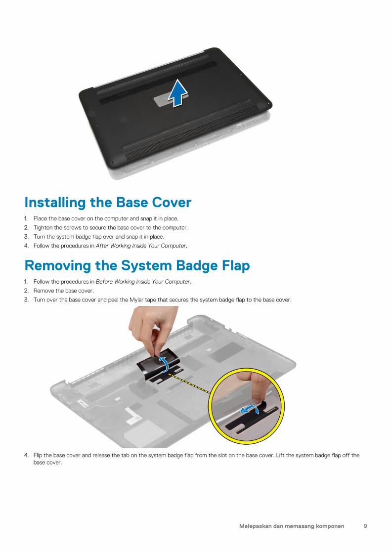
Installing the Base Cover1. Place the base cover on the computer and snap it in place.
2. Tighten the screws to secure the base cover to the computer.
3. Turn the system badge flap over and snap it in place.
4. Follow the procedures in After Working Inside Your Computer.
Removing the System Badge Flap1. Follow the procedures in Before Working Inside Your Computer.
2. Remove the base cover.
3. Turn over the base cover and peel the Mylar tape that secures the system badge flap to the base cover.
4. Flip the base cover and release the tab on the system badge flap from the slot on the base cover. Lift the system badge flap off the base cover.
Melepaskan dan memasang komponen 9
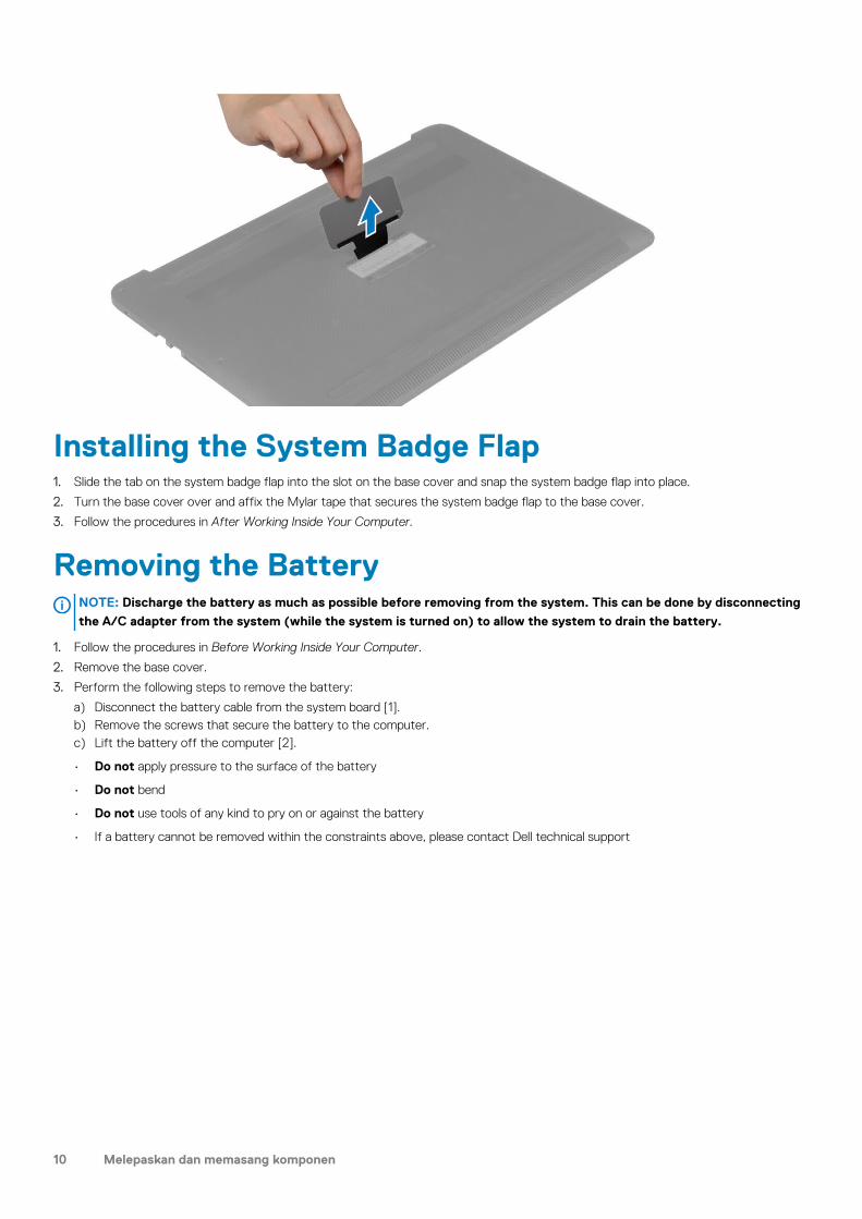
Installing the System Badge Flap1. Slide the tab on the system badge flap into the slot on the base cover and snap the system badge flap into place.
2. Turn the base cover over and affix the Mylar tape that secures the system badge flap to the base cover.
3. Follow the procedures in After Working Inside Your Computer.
Removing the BatteryNOTE: Discharge the battery as much as possible before removing from the system. This can be done by disconnecting
the A/C adapter from the system (while the system is turned on) to allow the system to drain the battery.
1. Follow the procedures in Before Working Inside Your Computer.
2. Remove the base cover.
3. Perform the following steps to remove the battery:
a) Disconnect the battery cable from the system board [1].b) Remove the screws that secure the battery to the computer.c) Lift the battery off the computer [2].
• Do not apply pressure to the surface of the battery
• Do not bend
• Do not use tools of any kind to pry on or against the battery
• If a battery cannot be removed within the constraints above, please contact Dell technical support
10 Melepaskan dan memasang komponen
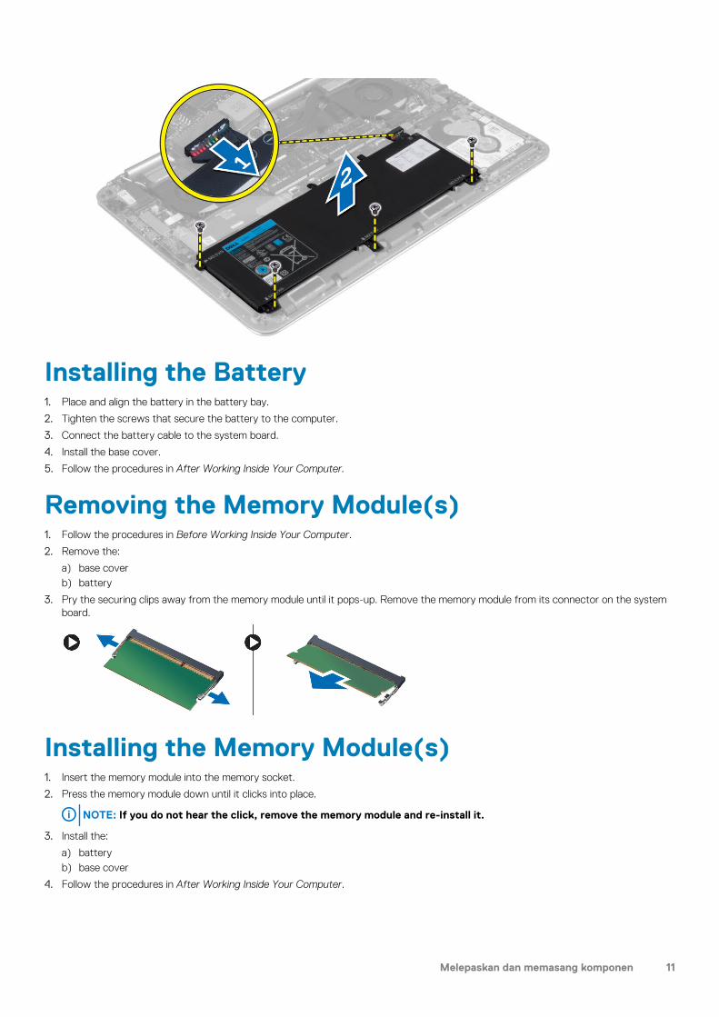
Installing the Battery1. Place and align the battery in the battery bay.
2. Tighten the screws that secure the battery to the computer.
3. Connect the battery cable to the system board.
4. Install the base cover.
5. Follow the procedures in After Working Inside Your Computer.
Removing the Memory Module(s)1. Follow the procedures in Before Working Inside Your Computer.
2. Remove the:
a) base coverb) battery
3. Pry the securing clips away from the memory module until it pops-up. Remove the memory module from its connector on the system board.
Installing the Memory Module(s)1. Insert the memory module into the memory socket.
2. Press the memory module down until it clicks into place.
NOTE: If you do not hear the click, remove the memory module and re-install it.
3. Install the:
a) batteryb) base cover
4. Follow the procedures in After Working Inside Your Computer.
Melepaskan dan memasang komponen 11
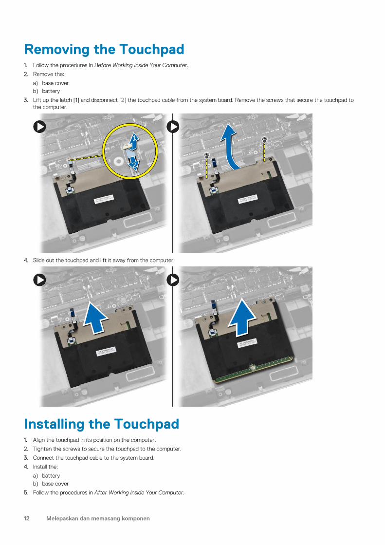
Removing the Touchpad1. Follow the procedures in Before Working Inside Your Computer.
2. Remove the:
a) base coverb) battery
3. Lift up the latch [1] and disconnect [2] the touchpad cable from the system board. Remove the screws that secure the touchpad to the computer.
4. Slide out the touchpad and lift it away from the computer.
Installing the Touchpad1. Align the touchpad in its position on the computer.
2. Tighten the screws to secure the touchpad to the computer.
3. Connect the touchpad cable to the system board.
4. Install the:
a) batteryb) base cover
5. Follow the procedures in After Working Inside Your Computer.
12 Melepaskan dan memasang komponen

Removing the Hard Drive1. Follow the procedures in Before Working Inside Your Computer.
2. Remove the:
a) base coverb) battery
3. Perform the following steps to remove the hard drive from the computer:
a) Disconnect the hard-drive cable from the system board [1].b) Remove the screws that secure the hard drive to the computer.c) Lift the hard drive off the computer [2].
4. Perform the following steps to remove the hard-drive bracket:
a) Disconnect the hard-drive cable from the hard drive [1].b) Remove the screws that secure the hard-drive bracket to the hard drive.c) Lift the hard drive off the hard-drive bracket [2].
Installing the Hard Drive1. Align the screw holes on the hard drive-bracket with the screw holes on the hard drive.
2. Tighten the screws that secure the hard-drive bracket to the hard drive.
Melepaskan dan memasang komponen 13

3. Connect the hard-drive cable to the hard drive.
4. Place the hard drive on its slot on the computer.
5. Tighten the screws to secure the hard drive to the computer.
6. Connect the hard-drive cable to the system board.
7. Install the:
a) batteryb) base cover
8. Follow the procedures in After Working Inside Your Computer.
Removing the Speakers 1. Follow the procedures in Before Working Inside Your Computer.
2. Remove the:
a) base coverb) battery
3. Perform the following steps to remove the speaker:
a) Disconnect the speaker cable from the system board [1].b) Unroute the speaker cable and remove the cable from the routing tabs [2].c) Remove the screw that secures the speakers to the computer.d) Lift the speakers, along with the speaker cable, off the computer [3].
Installing the Speakers1. Align the speakers in the slot on the computer.
2. Route the speaker cable through the routing tabs on the computer.
3. Tighten the screw to secure the speakers to the computer.
4. Connect the speaker cable to the system board.
5. Install the:
a) batteryb) base cover
6. Follow the procedures in After Working Inside Your Computer.
Removing the WLAN Card1. Follow the procedures in Before Working Inside Your Computer.
14 Melepaskan dan memasang komponen

2. Remove the:
a) base coverb) battery
3. Perform the following steps to remove the WLAN card:
a) Remove the screw to release the bracket that secures the WLAN card to the computer. Lift the bracket away from the computer.b) Disconnect the antenna cables from the WLAN card.c) Slide and remove the WLAN card from its connector on the I/O board.
Installing the WLAN Card1. Align the notch on the WLAN card with the tab on the WLAN-card connector on the I/O board.
2. Align the bracket which secures the WLAN card to the palmrest assembly.
3. Connect the antenna cables to the WLAN card.
CAUTION: To avoid damage to the WLAN card, do not place any cables under it.
NOTE: The color of the antenna cables is visible near the tip of the cables. The antenna-cable color scheme for the
WLAN card supported by your computer is as follows:
Table 1. Antenna-Cable Color Scheme for the WLAN Card
Connectors on the WLAN card Antenna-cable color
Main (white triangle) white
Auxiliary (black triangle) black
4. Tighten the screw to secure the bracket and the WLAN card to the palmrest assembly.
5. Install the:
a) batteryb) base cover
6. Follow the procedures in After Working Inside Your Computer.
Removing the Coin-Cell Battery1. Follow the procedures in Before Working Inside Your Computer.
CAUTION: Removing the coin-cell battery re-sets the BIOS settings to default. It is recommended that you note the
BIOS settings before removing the coin-cell battery.
2. Remove the:
a) base coverb) batteryc) WLAN card
3. Perform the following steps to remove the coin-cell battery:
a) Disconnect the coin-cell battery cable from the I/O board [1].b) Lift up and remove the coin-cell battery from the computer [2].
Melepaskan dan memasang komponen 15

Installing the Coin-Cell Battery1. Replace the coin-cell battery in its slot in the computer.
2. Connect the coin-cell battery cable to the I/O board.
3. Install the:
a) WLAN cardb) batteryc) base cover
4. Follow the procedures in After Working Inside Your Computer.
Removing the mSATA Card1. Follow the procedures in Before Working Inside Your Computer.
2. Remove the:
a) base coverb) battery
3. Disconnect the I/O-board cable from the system board and I/O board.
4. Remove the screw that secures the mSATA card to the computer. Remove the mSATA card from the system board.
16 Melepaskan dan memasang komponen
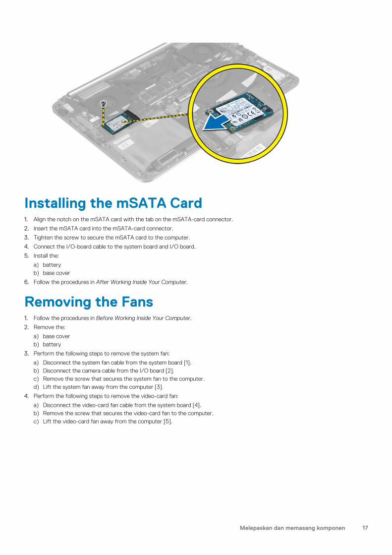
Installing the mSATA Card1. Align the notch on the mSATA card with the tab on the mSATA-card connector.
2. Insert the mSATA card into the mSATA-card connector.
3. Tighten the screw to secure the mSATA card to the computer.
4. Connect the I/O-board cable to the system board and I/O board.
5. Install the:
a) batteryb) base cover
6. Follow the procedures in After Working Inside Your Computer.
Removing the Fans1. Follow the procedures in Before Working Inside Your Computer.
2. Remove the:
a) base coverb) battery
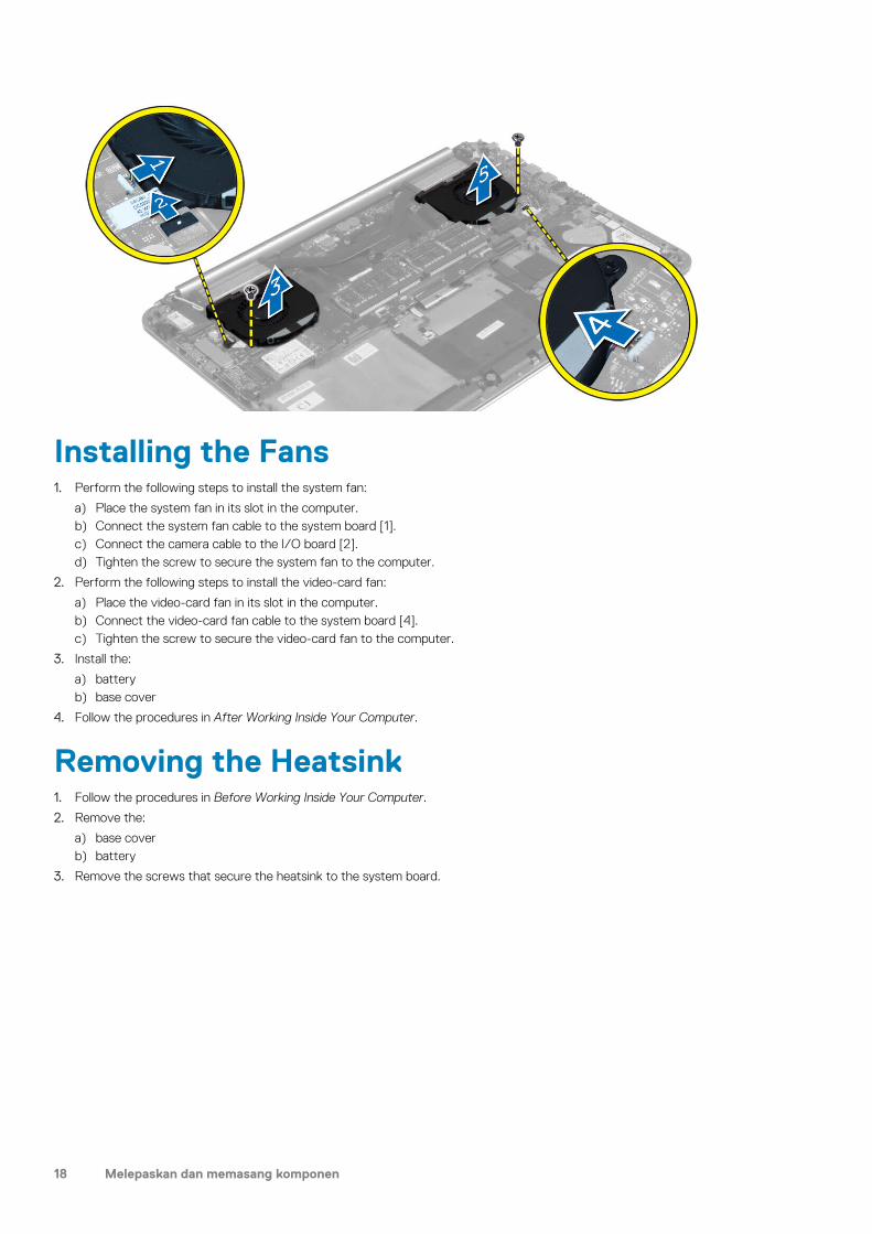
3. Perform the following steps to remove the system fan:
a) Disconnect the system fan cable from the system board [1].b) Disconnect the camera cable from the I/O board [2].c) Remove the screw that secures the system fan to the computer.d) Lift the system fan away from the computer [3].
4. Perform the following steps to remove the video-card fan:
a) Disconnect the video-card fan cable from the system board [4].b) Remove the screw that secures the video-card fan to the computer.c) Lift the video-card fan away from the computer [5].
Melepaskan dan memasang komponen 17
Installing the Fans1. Perform the following steps to install the system fan:
a) Place the system fan in its slot in the computer.b) Connect the system fan cable to the system board [1].c) Connect the camera cable to the I/O board [2].d) Tighten the screw to secure the system fan to the computer.
2. Perform the following steps to install the video-card fan:
a) Place the video-card fan in its slot in the computer.b) Connect the video-card fan cable to the system board [4].c) Tighten the screw to secure the video-card fan to the computer.
3. Install the:
a) batteryb) base cover
4. Follow the procedures in After Working Inside Your Computer.
Removing the Heatsink1. Follow the procedures in Before Working Inside Your Computer.
2. Remove the:
a) base coverb) battery
3. Remove the screws that secure the heatsink to the system board.
18 Melepaskan dan memasang komponen
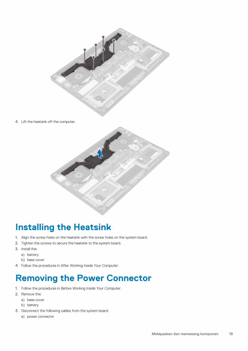
4. Lift the heatsink off the computer.
Installing the Heatsink1. Align the screw holes on the heatsink with the screw holes on the system board.
2. Tighten the screws to secure the heatsink to the system board.
3. Install the:
a) batteryb) base cover
4. Follow the procedures in After Working Inside Your Computer.
Removing the Power Connector1. Follow the procedures in Before Working Inside Your Computer.
2. Remove the:
a) base coverb) battery
3. Disconnect the following cables from the system board:
a) power connector
Melepaskan dan memasang komponen 19

b) touch panel
4. Perform the following steps to remove the power connector.
a) Release the power connector cable from under the display hinge [1].b) Remove the screw that secures the power connector to the palmrest assembly.c) Lift the power connector off the palmrest assembly [2].
Installing the Power Connector1. Tighten the screw to secure the power connector to the palmrest assembly.
2. Route the power connector cable under the display hinge.
3. Connect the following cables to the system board:
a) touch panelb) power connector
4. Install the:
a) batteryb) base cover
5. Follow the procedures in After Working Inside Your Computer.
Removing the Input/Output (I/O) Board1. Follow the procedures in Before Working Inside Your Computer.
2. Remove the:
a) base coverb) batteryc) WLAN cardd) coin-cell battery
3. Perform the following steps to remove the I/O board:
a) Disconnect the I/O board cable from the system board and the I/O board.b) Disconnect the camera, fan, and coin-cell battery cables from the I/O board.c) Remove the screws that secure the I/O board to the computer.d) Lift the I/O board from the computer.
20 Melepaskan dan memasang komponen
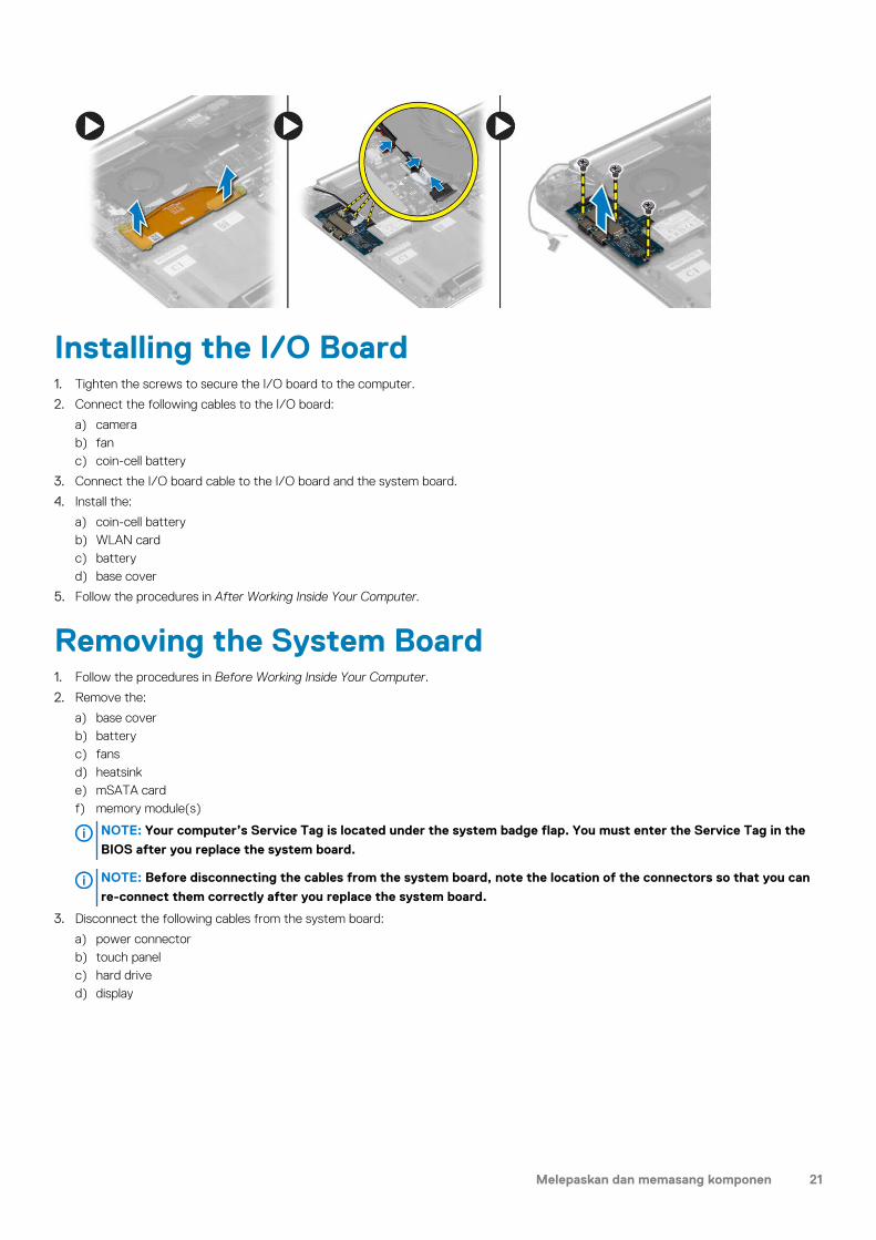
Installing the I/O Board1. Tighten the screws to secure the I/O board to the computer.
2. Connect the following cables to the I/O board:
a) camerab) fanc) coin-cell battery
3. Connect the I/O board cable to the I/O board and the system board.
4. Install the:
a) coin-cell batteryb) WLAN cardc) batteryd) base cover
5. Follow the procedures in After Working Inside Your Computer.
Removing the System Board1. Follow the procedures in Before Working Inside Your Computer.
2. Remove the:
a) base coverb) batteryc) fansd) heatsinke) mSATA cardf) memory module(s)
NOTE: Your computer’s Service Tag is located under the system badge flap. You must enter the Service Tag in the
BIOS after you replace the system board.
NOTE: Before disconnecting the cables from the system board, note the location of the connectors so that you can
re-connect them correctly after you replace the system board.
3. Disconnect the following cables from the system board:
a) power connectorb) touch panelc) hard drived) display
Melepaskan dan memasang komponen 21

4. Lift the connector latches [1] to disconnect [2] the following cables from the system board:
a) keyboard backlightb) touchpadc) keyboard (after peeling off the tape and lifting the connector latch)d) speaker
5. Perform the following steps to remove the system board from the computer:
a) Loosen the captive screws that secure the system board to the computer.b) Remove the screws that secure the system board to the computer.c) Lift the system board off the computer.
22 Melepaskan dan memasang komponen

Installing the System Board1. Align the system board on the computer.
2. Tighten the screws and the captive screws to secure the system board to the computer.
3. Slide the keyboard cable in the connector and press down on the connector latch to secure the cable.
4. Adhere the tape to the keyboard-cable connector.
5. Route the following cables on the system board and press down on the connector latches to secure the cables:
a) speakerb) keyboard (affix the tape)c) touchpadd) keyboard backlight
6. Connect the following cables to the system board:
a) displayb) hard drivec) touch paneld) power connector
CAUTION: Make sure that no cables are placed under the system board.
7. Install the:
a) memory module(s)b) mSATA cardc) heatsinkd) fanse) batteryf) base cover
8. Follow the procedures in After Working Inside Your Computer.
Removing the Keyboard1. Follow the procedures in Before Working Inside Your Computer.
2. Remove the:
a) base coverb) batteryc) fansd) heatsinke) mSATA card
Melepaskan dan memasang komponen 23
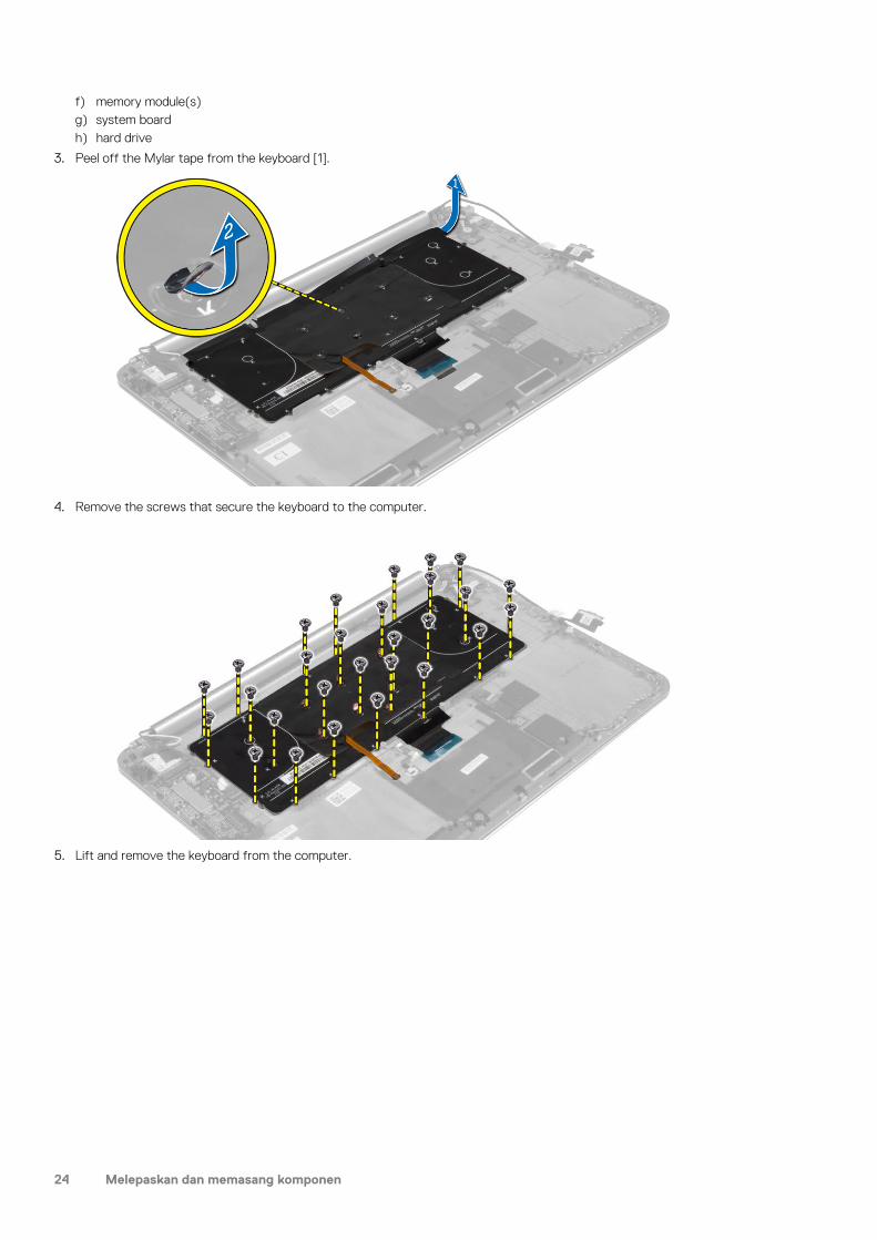
f) memory module(s)g) system boardh) hard drive
3. Peel off the Mylar tape from the keyboard [1].
4. Remove the screws that secure the keyboard to the computer.
5. Lift and remove the keyboard from the computer.
24 Melepaskan dan memasang komponen
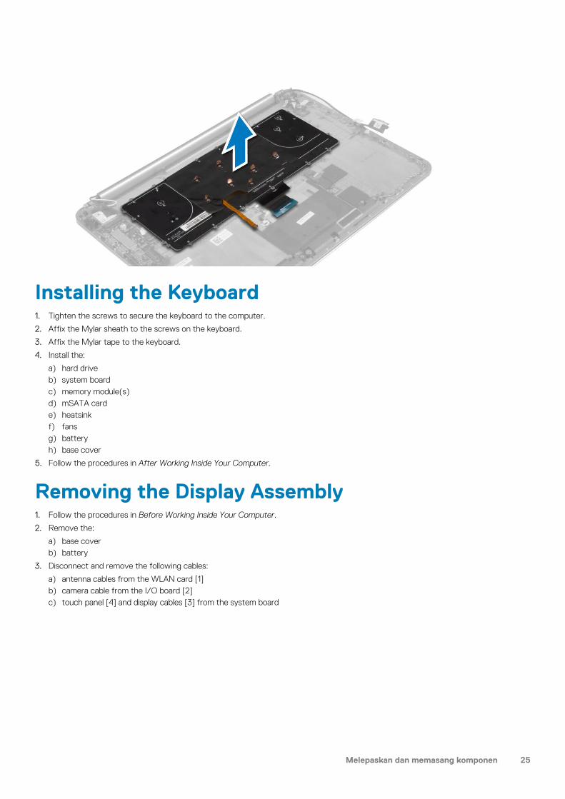
Installing the Keyboard1. Tighten the screws to secure the keyboard to the computer.
2. Affix the Mylar sheath to the screws on the keyboard.
3. Affix the Mylar tape to the keyboard.
4. Install the:
a) hard driveb) system boardc) memory module(s)d) mSATA carde) heatsinkf) fansg) batteryh) base cover
5. Follow the procedures in After Working Inside Your Computer.
Removing the Display Assembly1. Follow the procedures in Before Working Inside Your Computer.
2. Remove the:
a) base coverb) battery
3. Disconnect and remove the following cables:
a) antenna cables from the WLAN card [1]b) camera cable from the I/O board [2]c) touch panel [4] and display cables [3] from the system board
Melepaskan dan memasang komponen 25

4. Remove the screws that secure the display hinges to the palmrest assembly.
5. Lift and remove the palmrest assembly from the display assembly.
CAUTION: Lift the palmrest assembly slowly to avoid damaging the display assembly.
26 Melepaskan dan memasang komponen
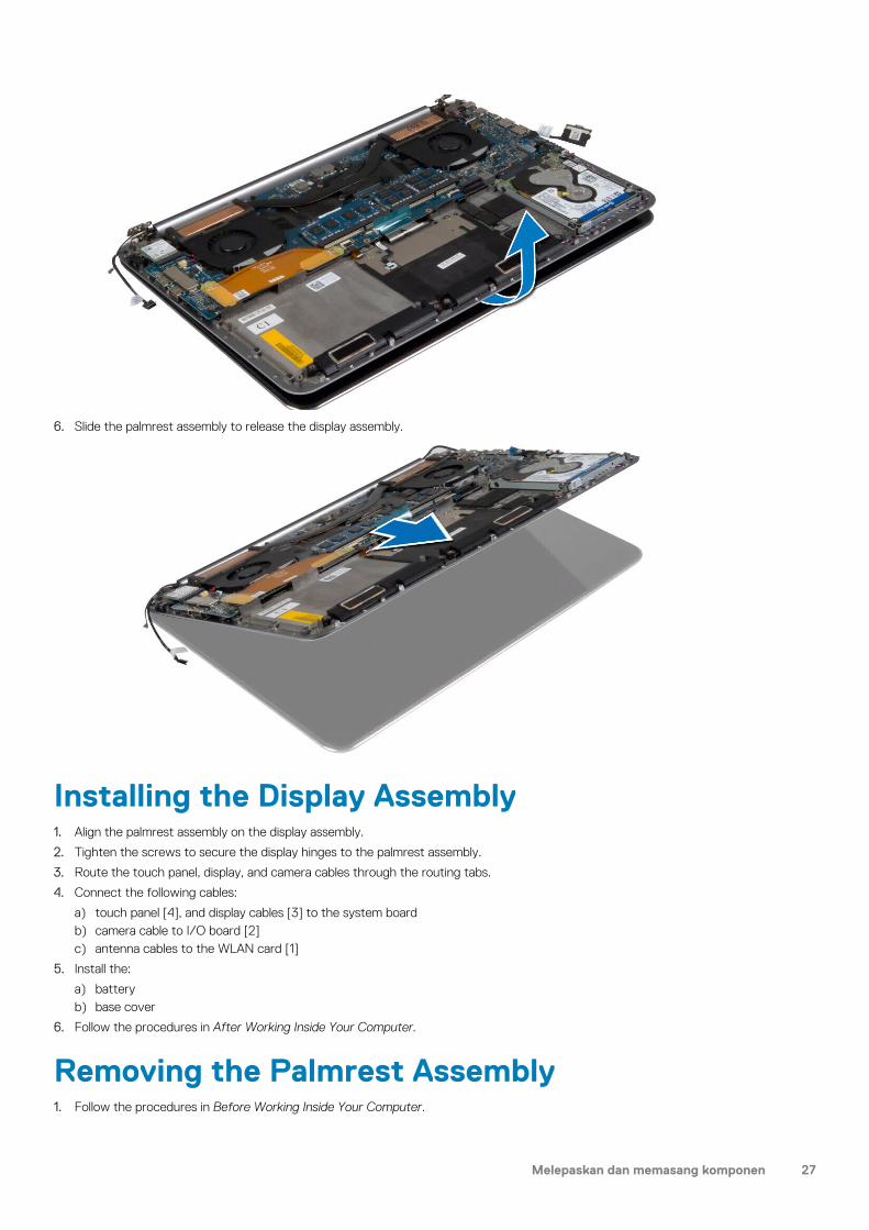
6. Slide the palmrest assembly to release the display assembly.
Installing the Display Assembly1. Align the palmrest assembly on the display assembly.
2. Tighten the screws to secure the display hinges to the palmrest assembly.
3. Route the touch panel, display, and camera cables through the routing tabs.
4. Connect the following cables:
a) touch panel [4], and display cables [3] to the system boardb) camera cable to I/O board [2]c) antenna cables to the WLAN card [1]
5. Install the:
a) batteryb) base cover
6. Follow the procedures in After Working Inside Your Computer.
Removing the Palmrest Assembly1. Follow the procedures in Before Working Inside Your Computer.
Melepaskan dan memasang komponen 27

2. Remove the:
a) base coverb) batteryc) hard drived) speakerse) WLAN cardf) coin-cell batteryg) mSATA cardh) fansi) heatsinkj) power connectork) I/O boardl) memory module(s)m) system boardn) keyboard
3. Remove the screws that secure the display hinges to the palmrest assembly.
4. Lift the palmrest assembly away from the display assembly.
CAUTION: Lift the palmrest assembly slowly to avoid damaging the display assembly.
5. Remove the palmrest assembly away from the display assembly.
28 Melepaskan dan memasang komponen
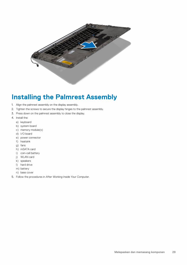
Installing the Palmrest Assembly1. Align the palmrest assembly on the display assembly.
2. Tighten the screws to secure the display hinges to the palmrest assembly.
3. Press down on the palmrest assembly to close the display.
4. Install the:
a) keyboardb) system boardc) memory module(s)d) I/O boarde) power connectorf) heatsinkg) fansh) mSATA cardi) coin-cell batteryj) WLAN cardk) speakersl) hard drivem) batteryn) base cover
5. Follow the procedures in After Working Inside Your Computer.
Melepaskan dan memasang komponen 29
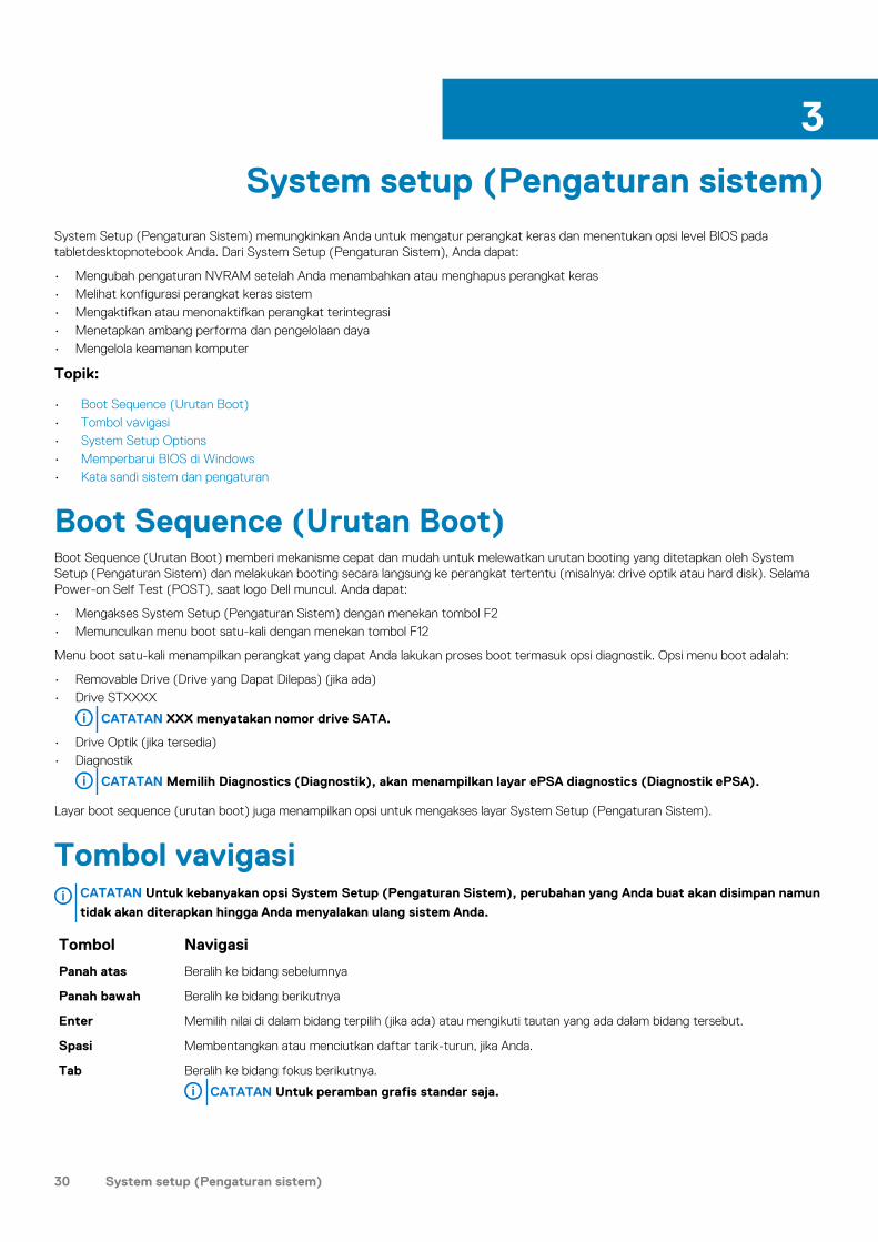
System setup (Pengaturan sistem)System Setup (Pengaturan Sistem) memungkinkan Anda untuk mengatur perangkat keras dan menentukan opsi level BIOS pada tabletdesktopnotebook Anda. Dari System Setup (Pengaturan Sistem), Anda dapat:
• Mengubah pengaturan NVRAM setelah Anda menambahkan atau menghapus perangkat keras• Melihat konfigurasi perangkat keras sistem• Mengaktifkan atau menonaktifkan perangkat terintegrasi• Menetapkan ambang performa dan pengelolaan daya• Mengelola keamanan komputer
Topik:
• Boot Sequence (Urutan Boot)• Tombol vavigasi• System Setup Options• Memperbarui BIOS di Windows • Kata sandi sistem dan pengaturan
Boot Sequence (Urutan Boot)Boot Sequence (Urutan Boot) memberi mekanisme cepat dan mudah untuk melewatkan urutan booting yang ditetapkan oleh System Setup (Pengaturan Sistem) dan melakukan booting secara langsung ke perangkat tertentu (misalnya: drive optik atau hard disk). Selama Power-on Self Test (POST), saat logo Dell muncul. Anda dapat:
• Mengakses System Setup (Pengaturan Sistem) dengan menekan tombol F2• Memunculkan menu boot satu-kali dengan menekan tombol F12
Menu boot satu-kali menampilkan perangkat yang dapat Anda lakukan proses boot termasuk opsi diagnostik. Opsi menu boot adalah:
• Removable Drive (Drive yang Dapat Dilepas) (jika ada)• Drive STXXXX
CATATAN XXX menyatakan nomor drive SATA.
• Drive Optik (jika tersedia)• Diagnostik
CATATAN Memilih Diagnostics (Diagnostik), akan menampilkan layar ePSA diagnostics (Diagnostik ePSA).
Layar boot sequence (urutan boot) juga menampilkan opsi untuk mengakses layar System Setup (Pengaturan Sistem).
Tombol vavigasiCATATAN Untuk kebanyakan opsi System Setup (Pengaturan Sistem), perubahan yang Anda buat akan disimpan namun
tidak akan diterapkan hingga Anda menyalakan ulang sistem Anda.
Tombol Navigasi
Panah atas Beralih ke bidang sebelumnya
Panah bawah Beralih ke bidang berikutnya
Enter Memilih nilai di dalam bidang terpilih (jika ada) atau mengikuti tautan yang ada dalam bidang tersebut.
Spasi Membentangkan atau menciutkan daftar tarik-turun, jika Anda.
Tab Beralih ke bidang fokus berikutnya.
CATATAN Untuk peramban grafis standar saja.
3
30 System setup (Pengaturan sistem)
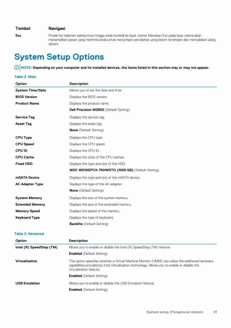
Tombol Navigasi
Esc Pindah ke halaman sebelumnya hingga anda kembali ke layar utama. Menekan Esc pada layar utama akan menampilkan pesan yang meminta anda untuk menyimpan perubahan yang belum tersimpan dan menyalakan ulang sistem.
System Setup OptionsNOTE: Depending on your computer and its installed devices, the items listed in this section may or may not appear.
Table 2. Main
Option Description
System Time/Date Allows you to set the date and time.
BIOS Version Displays the BIOS version.
Product Name Displays the product name.
Dell Precision M3800 (Default Setting)
Service Tag Displays the service tag.
Asset Tag Displays the asset tag.
None (Default Setting)
CPU Type Displays the CPU type.
CPU Speed Displays the CPU speed.
CPU ID Displays the CPU ID.
CPU Cache Displays the sizes of the CPU caches.
Fixed HDD Displays the type and size of the HDD.
WDC WD10SPCX-75HWSTO (1000 GB) (Default Setting)
mSATA Device Displays the type and size of the mSATA device.
AC Adapter Type Displays the type of the AC adapter.
None (Default Setting)
System Memory Displays the size of the system memory.
Extended Memory Displays the size of the extended memory.
Memory Speed Displays the speed of the memory.
Keyboard Type Displays the type of keyboard.
Backlite (Default Setting)
Table 3. Advanced
Option Description
Intel (R) SpeedStep (TM) Allows you to enable or disable the Intel (R) SpeedStep (TM) feature.
Enabled (Default Setting)
Virtualization This option specifies whether a Virtual Machine Monitor (VMM) can utilize the additional hardware capabilities provided by Intel Virtualization technology. Allows you to enable or disable the Virtualization feature.
Enabled (Default Setting)
USB Emulation Allows you to enable or disable the USB Emulation feature.
Enabled (Default Setting)
System setup (Pengaturan sistem) 31
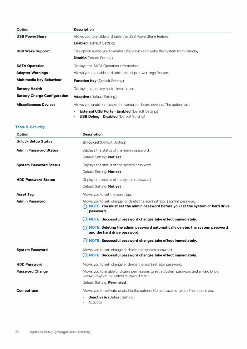
Option Description
USB PowerShare Allows you to enable or disable the USB PowerShare feature.
Enabled (Default Setting)
USB Wake Support This option allows you to enable USB devices to wake the system from Standby.
Disable(Default Setting)
SATA Operation Displays the SATA Operation information.
Adapter Warnings Allows you to enable or disable the adapter warnings feature.
Multimedia Key Behaviour Function Key (Default Setting)
Battery Health Displays the battery health information.
Battery Charge Configuration Adaptive (Default Setting)
Miscellaneous Devices Allows you enable or disable the various on board devices. The options are:
• External USB Ports - Enabled (Default Setting)• USB Debug - Disabled (Default Setting)
Table 4. Security
Option Description
Unlock Setup Status Unlocked (Default Setting)
Admin Password Status Displays the status of the admin password.
Default Setting: Not set
System Password Status Displays the status of the system password.
Default Setting: Not set
HDD Password Status Displays the status of the system password.
Default Setting: Not set
Asset Tag Allows you to set the asset tag.
Admin Password Allows you to set, change, or delete the administrator (admin) password.NOTE: You must set the admin password before you set the system or hard drive password.
NOTE: Successful password changes take effect immediately.
NOTE: Deleting the admin password automatically deletes the system password and the hard drive password.
NOTE: Successful password changes take effect immediately.
System Password Allows you to set, change or delete the system password.
NOTE: Successful password changes take effect immediately.
HDD Password Allows you to set, change or delete the administrator password.
Password Change Allows you to enable or disable permissions to set a System password and a Hard Drive password when the admin password is set.
Default Setting: Permitted
Computrace Allows you to activate or disable the optional Computrace software The options are:
• Deactivate (Default Setting)• Activate
32 System setup (Pengaturan sistem)
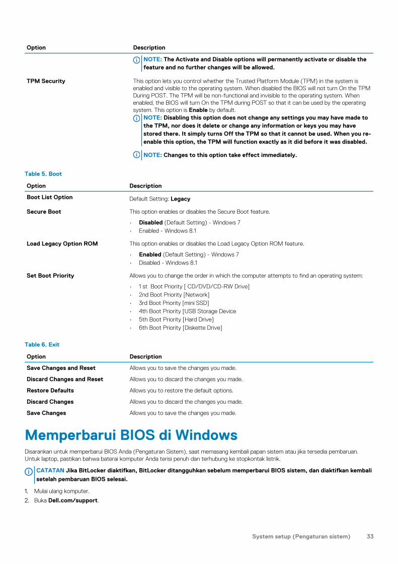
Option Description
NOTE: The Activate and Disable options will permanently activate or disable the feature and no further changes will be allowed.
TPM Security This option lets you control whether the Trusted Platform Module (TPM) in the system is enabled and visible to the operating system. When disabled the BIOS will not turn On the TPM During POST. The TPM will be non-functional and invisible to the operating system. When enabled, the BIOS will turn On the TPM during POST so that it can be used by the operating system. This option is Enable by default.
NOTE: Disabling this option does not change any settings you may have made to the TPM, nor does it delete or change any information or keys you may have stored there. It simply turns Off the TPM so that it cannot be used. When you re-enable this option, the TPM will function exactly as it did before it was disabled.
NOTE: Changes to this option take effect immediately.
Table 5. Boot
Option Description
Boot List Option Default Setting: Legacy
Secure Boot This option enables or disables the Secure Boot feature.
• Disabled (Default Setting) - Windows 7• Enabled - Windows 8.1
Load Legacy Option ROM This option enables or disables the Load Legacy Option ROM feature.
• Enabled (Default Setting) - Windows 7• Disabled - Windows 8.1
Set Boot Priority Allows you to change the order in which the computer attempts to find an operating system:
• 1 st Boot Priority [ CD/DVD/CD-RW Drive]• 2nd Boot Priority [Network]• 3rd Boot Priority [mini SSD]• 4th Boot Priority [USB Storage Device• 5th Boot Priority [Hard Drive]• 6th Boot Priority [Diskette Drive]
Table 6. Exit
Option Description
Save Changes and Reset Allows you to save the changes you made.
Discard Changes and Reset Allows you to discard the changes you made.
Restore Defaults Allows you to restore the default options.
Discard Changes Allows you to discard the changes you made.
Save Changes Allows you to save the changes you made.
Memperbarui BIOS di WindowsDisarankan untuk memperbarui BIOS Anda (Pengaturan Sistem), saat memasang kembali papan sistem atau jika tersedia pembaruan. Untuk laptop, pastikan bahwa baterai komputer Anda terisi penuh dan terhubung ke stopkontak listrik.
CATATAN Jika BitLocker diaktifkan, BitLocker ditangguhkan sebelum memperbarui BIOS sistem, dan diaktifkan kembali
setelah pembaruan BIOS selesai.
1. Mulai ulang komputer.
2. Buka Dell.com/support.
System setup (Pengaturan sistem) 33
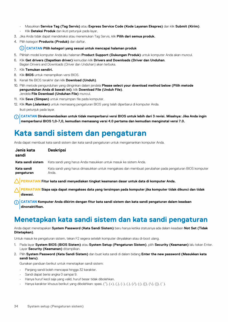
• Masukkan Service Tag (Tag Servis) atau Express Service Code (Kode Layanan Ekspres) dan klik Submit (Kirim).• Klik Deteksi Produk dan ikuti petunjuk pada layar,
3. Jika Anda tidak dapat mendeteksi atau menemukan Tag Servis, klik Pilih dari semua produk.
4. Pilih kategori Products (Produk) dari daftar.
CATATAN Pilih kategori yang sesuai untuk mencapai halaman produk
5. Pilihlah model komputer Anda lalu halaman Product Support (Dukungan Produk) untuk komputer Anda akan muncul.
6. Klik Get drivers (Dapatkan driver) kemudian klik Drivers and Downloads (Driver dan Unduhan.Bagian Drivers and Downloads (Driver dan Unduhan) akan terbuka.
7. Klik Temukan sendiri.
8. Klik BIOS untuk menampilkan versi BIOS.
9. Kenali file BIOS terakhir dan klik Download (Unduh).
10. Pilih metode pengunduhan yang diinginkan dalam jendela Please select your download method below (Pilih metode pengunduhan Anda di bawah ini); klik Download File (Unduh File).Jendela File Download (Unduhan File) muncul.
11. Klik Save (Simpan) untuk menyimpan file pada komputer.
12. Klik Run (Jalankan) untuk memasang pengaturan BIOS yang telah diperbarui di komputer Anda.
Ikuti petunjuk pada layar.
CATATAN Direkomendasikan untuk tidak memperbarui versi BIOS untuk lebih dari 3 revisi. Misalnya: Jika Anda ingin
memperbarui BIOS 1,0-7,0, kemudian memasang versi 4.0 pertama dan kemudian menginstal versi 7.0.
Kata sandi sistem dan pengaturanAnda dapat membuat kata sandi sistem dan kata sandi pengaturan untuk mengamankan komputer Anda.
Jenis kata sandi
Deskripsi
Kata sandi sistem Kata sandi yang harus Anda masukkan untuk masuk ke sistem Anda.
Kata sandi pengaturan
Kata sandi yang harus dimasukkan untuk mengakses dan membuat perubahan pada pengaturan BIOS komputer Anda.
PERHATIAN Fitur kata sandi menyediakan tingkat keamanan dasar untuk data di komputer Anda.
PERHATIAN Siapa saja dapat mengakses data yang tersimpan pada komputer jika komputer tidak dikunci dan tidak
diawasi.
CATATAN Komputer Anda dikirim dengan fitur kata sandi sistem dan kata sandi pengaturan dalam keadaan
dinonaktifkan.
Menetapkan kata sandi sistem dan kata sandi pengaturanAnda dapat menetapakan System Password (Kata Sandi Sistem) baru hanya ketika statusnya ada dalam keadaan Not Set (Tidak Ditetapkan).
Untuk masuk ke pengaturan sistem, tekan F2 segera setelah komputer dinyalakan atau di-boot ulang.
1. Pada layar System BIOS (BIOS Sistem) atau System Setup (Pengaturan Sistem), pilih Security (Keamanan) lalu tekan Enter.Layar Security (Keamanan) ditampilkan.
2. Pilih System Password (Kata Sandi Sistem) dan buat kata sandi di dalam bidang Enter the new password (Masukkan kata sandi baru).
Gunakan panduan berikut untuk menetapkan sandi sistem:
• Panjang sandi boleh mencapai hingga 32 karakter.• Sandi dapat berisi angka 0 sampai 9.• Hanya huruf kecil saja yang valid, huruf besar tidak dibolehkan.• Hanya karakter khusus berikut yang dibolehkan: spasi, (”), (+), (,), (-), (.), (/), (;), ([), (\), (]), (`).
34 System setup (Pengaturan sistem)
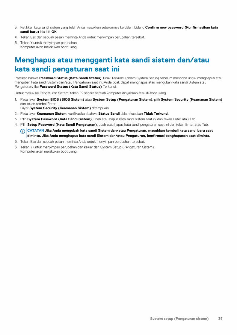
3. Ketikkan kata sandi sistem yang telah Anda masukkan sebelumnya ke dalam bidang Confirm new password (Konfirmasikan kata sandi baru) lalu klik OK.
4. Tekan Esc dan sebuah pesan meminta Anda untuk menyimpan perubahan tersebut.
5. Tekan Y untuk menyimpan perubahan.Komputer akan melakukan boot ulang.
Menghapus atau mengganti kata sandi sistem dan/atau kata sandi pengaturan saat iniPastikan bahwa Password Status (Kata Sandi Status) Tidak Terkunci (dalam System Setup) sebelum mencoba untuk menghapus atau mengubah kata sandi Sistem dan/atau Pengaturan saat ini. Anda tidak dapat menghapus atau mengubah kata sandi Sistem atau Pengaturan, jika Password Status (Kata Sandi Status) Terkunci.
Untuk masuk ke Pengaturan Sistem, tekan F2 segera setelah komputer dinyalakan atau di-boot ulang.
1. Pada layar System BIOS (BIOS Sistem) atau System Setup (Pengaturan Sistem), pilih System Security (Keamanan Sistem) dan tekan tombol Enter.Layar System Security (Keamanan Sistem) ditampilkan.
2. Pada layar Keamanan Sistem, verifikasikan bahwa Status Sandi dalam keadaan Tidak Terkunci.
3. Pilih System Password (Kata Sandi Sistem), ubah atau hapus kata sandi sistem saat ini dan tekan Enter atau Tab.
4. Pilih Setup Password (Kata Sandi Pengaturan), ubah atau hapus kata sandi pengaturan saat ini dan tekan Enter atau Tab.
CATATAN Jika Anda mengubah kata sandi Sistem dan/atau Pengaturan, masukkan kembali kata sandi baru saat
diminta. Jika Anda menghapus kata sandi Sistem dan/atau Pengaturan, konfirmasi penghapusan saat diminta.
5. Tekan Esc dan sebuah pesan meminta Anda untuk menyimpan perubahan tersebut.
6. Tekan Y untuk menyimpan perubahan dan keluar dari System Setup (Pengaturan Sistem).Komputer akan melakukan boot ulang.
System setup (Pengaturan sistem) 35
DiagnostikJika Anda menghadapi masalah pada komputer, jalankan diagnostik ePSA sebelum menghubungi Dell untuk mendapatkan bantuan teknis. Tujuan menjalankan diagnostik adalah untuk menguji perangkat keras komputer tanpa memerlukan peralatan tambahan atau membahayakan data. Jika Anda tidak dapat menyelesaikan masalahnya sendiri, personel layanan dan dukungan dapat menggunakan hasil diagnosis untuk menyelesaikan masalah.Topik:
• Diagnostik Enhanced Pre-Boot System Assessment (ePSA)• Device Status Light
Diagnostik Enhanced Pre-Boot System Assessment (ePSA)Diagnostik EPSA (juga dikenal sebagai sistem diagnostik) melakukan pemeriksaan lengkap hardware Anda. EPSA tertanam dengan BIOS dan diluncurkan oleh BIOS secara internal. Diagnostik sistem tertanam memberikan satu set opsi untuk grup perangkat tertentu atau perangkat yang memungkinkan Anda untuk:
• Menjalankan tes secara otomatis atau dalam modus interaktif• Mengulangi tes• Menampilkan atau menyimpan hasil tes• Menjalankan tes secara menyeluruh untuk memperkenalkan opsi tes tambahan untuk menyediakan informasi ekstra tentang perangkat
yang gagal• Melihat pesan status yang memberi tahu Anda jika tes telah berhasil diselesaikan• Melihat pesan galat yang memberi tahu Anda tentang masalah yang dijumpai selama pengetesan
PERHATIAN Gunakan sistem diagnostik untuk menguji hanya komputer Anda. Menggunakan program ini dengan
komputer lain dapat menyebabkan hasil yang tidak valid atau pesan kesalahan.
CATATAN Beberapa tes untuk perangkat tertentu membutuhkan interaksi pengguna. Selalu pastikan bahwa Anda hadir
di terminal komputer ketika tes diagnostik dilakukan.
Device Status LightIcon Description
Turns on when you turn on the computer.
4
36 Diagnostik

Technical Specifications
NOTE: Offerings may vary by region. For more information regarding the configuration of your computer, click Start
(Start icon) > Help and Support, and then select the option to view information about your computer.
Table 7. System Information
Feature Specification
System Chipset Mobile Intel 8 Series Chipset
DMA Channels two VT-d DMA remap engines
Interrupt Levels Intel 64 and IA-32 Architecture
BIOS Chip (NVRAM) 8 MB
Table 8. Processor
Feature Specification
Processor type Intel Core i7 Quad Core
L1 cache up to 256 KB cache depending on processor type
L2 cache up to 1024 KB cache depending on processor type
L3 cache up to 6144 KB cache depending on processor type
Table 9. Memory
Feature Specification
Type DDR3L
Speed 1600 MHz
Connectors 2 SoDIMM Sockets
Capacity 8 GB, 12 GB, and 16 GB
Minimum Memory 8 GB
Maximum memory 16 GB
Table 10. Video
Feature Specification
Type discrete
Data bus PCIE x16, Gen3
Video controller and memory: NVIDIA Quadro K1100M , 2 GB GDDR5(4 Pcs 128Mx32), 1.5 V based
Table 11. Audio
Feature Specification
Integrated dual-channel High-Definition audio
Table 12. Communication
Feature Specification
Network adapter ethernet via USB-to-Ethernet Dongle provided in box.
5
Technical Specifications 37

Feature Specification
NOTE: No RJ45 (10/100/1000Base-T, IPv6) provided.
Wireless wireless On/Off implemented via keyboard wireless key
• WLAN and Bluetooth BT 4.0 + LE combo card support• Bluetooth 2.1/3.0/4.0/4.1 with Wi-Fi combo module
Table 13. Ports and Connectors
Feature Specification
Audio • Microphone/Headphone Universal Audio jack support• Autosense Headphone/Microphone combo jack support (1/8 inches
connector)
USB 2.0 one
USB 3.0 three
Video • Mini-DisplayPort DP 1.2 support• HDMI 1.4a with audio; Intel Media Vault support through HDMI port
Memory card reader SD 4.0
Table 14. Display
Feature Specification
Type 1366 X 768 pixels
Size 15.6 inches
Dimensions:
Height 254.0 mm (9.99 inches)
Width 372.0 mm (14.64 inches)
Diagonal 396.24 mm (15.60 inches)
Active area (X/Y) 344.16 mm X 193.59 mm / 345.60 mm X 194.40 mm (13.5 inches X 7.62 inches / 13.60 inches X 7.65 inches)
Maximum resolution 1920 X 1080 pixels / 3200 X 1800 pixels
Maximum Brightness 400 nits
Operating angle 0° (closed) to 135°
Refresh rate 60 Hz
Minimum viewing angles:
Horizontal 80/80
Vertical 80/80
Table 15. Keyboard
Feature Specification
Number of keys • United States: 80 keys• United Kingdom: 81 keys• Brazil: 81 keys• Japan: 84 keys
Layout QWERTY/AZERTY/Kanji
38 Technical Specifications

Table 16. Touchpad
Feature Specification
Active Area:
X-axis 105 mm
Y-axis 80 mm
Table 17. Camera
Feature Specification
Type HD Camera / Digital Array Microphone
Still Resolution 0.92 megapixels (Maximum)
Video Resolution 1280 x 720 pixels at 30 frames per second (Maximum)
Diagonal 74 degrees
Table 18. Storage
Feature Specification
Storage:
Storage Interface SATA 3 (6 Gb/s)
Drives configurations:
Hard Drives (optional) one internal 2.5 inch SATA HDD
Solid State Drives (optional) one Solid State Drive (SSD), Full Mini Card (FMC)
Size: 128 GB, 256 GB, 500 GB, 512 GB, and 1 TB
Table 19. Battery
Feature Specification
Type Li-polymer 6-cell (61 Wh) / 6-cell (91 Wh)
Dimensions :
61 Wh :
Depth 92.65 mm (3.64 inches)
Height 9 mm (0.35 inches)
Width 270 mm (10.62 inches)
Weight 320 g (0.70 lb)
91 Wh :
Depth 92.65 mm (3.64 inches)
Height 9 mm (0.35 inches)
Width 342.45 mm (13.48 inches)
Weight 443 g (0.97 lb)
Voltage 11.1 V
Life span 300 discharge/charge cycles
Temperature range:
Operating (approximate) • Charge : 0 °C to 50 °C (32 °F to 158 °F)• Discharge: 0 °C to 70 °C (32 °F to 122 °F)• Operating: 0 °C to 35 °C (32 °F to 95 °F)
Non-operating –40 °C to 65 °C (–40 °F to 149 °F)
Technical Specifications 39
Feature Specification
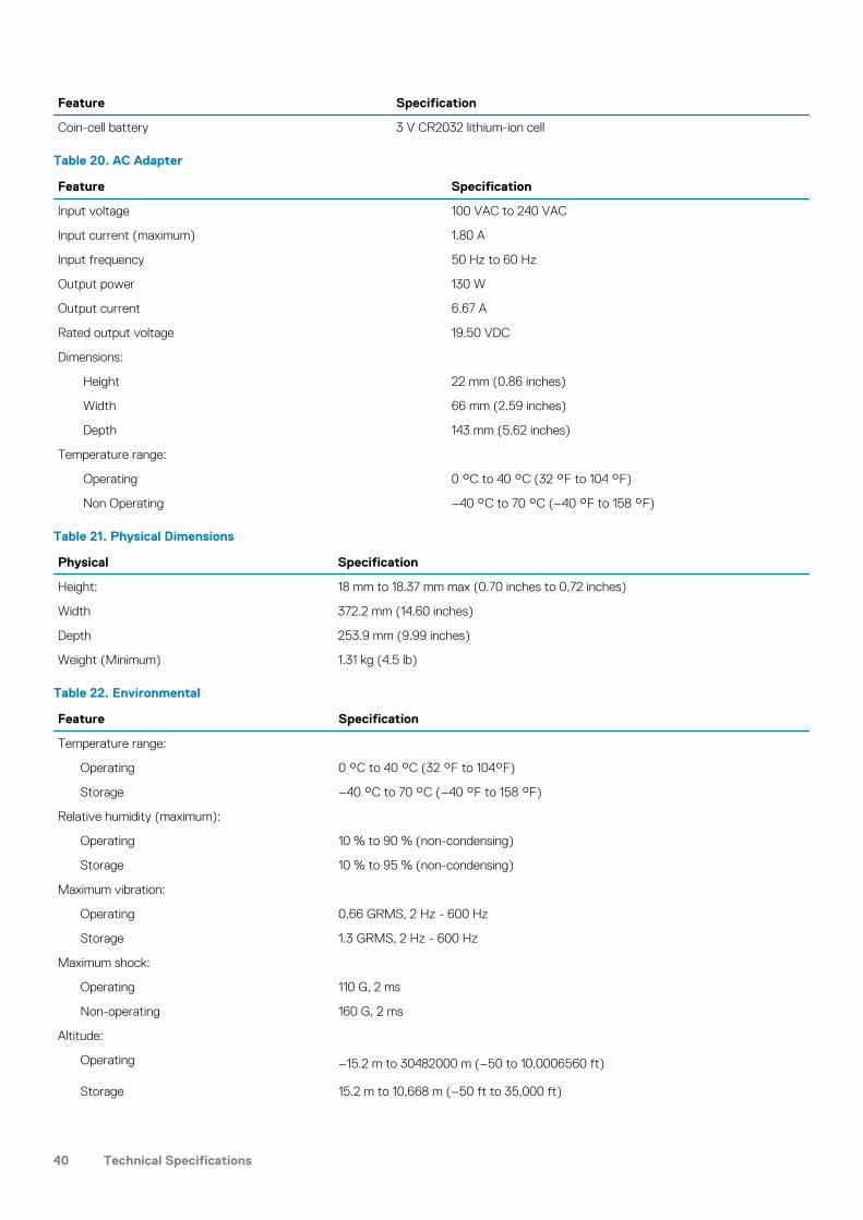
Coin-cell battery 3 V CR2032 lithium-ion cell
Table 20. AC Adapter
Feature Specification
Input voltage 100 VAC to 240 VAC
Input current (maximum) 1.80 A
Input frequency 50 Hz to 60 Hz
Output power 130 W
Output current 6.67 A
Rated output voltage 19.50 VDC
Dimensions:
Height 22 mm (0.86 inches)
Width 66 mm (2.59 inches)
Depth 143 mm (5.62 inches)
Temperature range:
Operating 0 °C to 40 °C (32 °F to 104 °F)
Non Operating –40 °C to 70 °C (–40 °F to 158 °F)
Table 21. Physical Dimensions
Physical Specification
Height: 18 mm to 18.37 mm max (0.70 inches to 0.72 inches)
Width 372.2 mm (14.60 inches)
Depth 253.9 mm (9.99 inches)
Weight (Minimum) 1.31 kg (4.5 lb)
Table 22. Environmental
Feature Specification
Temperature range:
Operating 0 °C to 40 °C (32 °F to 104°F)
Storage –40 °C to 70 °C (–40 °F to 158 °F)
Relative humidity (maximum):
Operating 10 % to 90 % (non-condensing)
Storage 10 % to 95 % (non-condensing)
Maximum vibration:
Operating 0.66 GRMS, 2 Hz - 600 Hz
Storage 1.3 GRMS, 2 Hz - 600 Hz
Maximum shock:
Operating 110 G, 2 ms
Non-operating 160 G, 2 ms
Altitude:
Operating –15.2 m to 30482000 m (–50 to 10,0006560 ft)
Storage 15.2 m to 10,668 m (–50 ft to 35,000 ft)
40 Technical Specifications
Feature Specification
Airborne contaminant level G1 as defined by ISA-S71.04-1985
Technical Specifications 41
Menghubungi DellCATATAN Jika Anda tidak memiliki sambungan Internet aktif, Anda dapat menemukan informasi kontak pada faktur
pembelian, slip kemasan, tagihan, atau katalog produk Dell.
Dell menyediakan beberapa dukungan berbasis online dan telepon serta opsi servis. Ketersediaan bervariasi menurut negara dan produk, dan sebagian layanan mungkin tidak tersedia di daerah Anda. Untuk menghubungi Dell atas masalah penjualan, dukungan teknis, atau layanan pelanggan:
1. Buka Dell.com/support.
2. Pilih kategori dukungan Anda.
3. Verifikasikan negara atau kawasan Anda di daftar tarik turun Choose A Country/Region (Pilih Negara/Kawasan) pada bagian bawah halaman.
4. Pilih tautan layanan atau tautan yang terkait berdasarkan kebutuhan Anda.
6
42 Menghubungi Dell